International Journal of Scientific & Engineering Research, Volume 4, Issue 9, September-2013 2436
ISSN 2229-5518
Comparitive Analysis for Reduction of Exhaust Emissions for Two Stroke and Four Stroke Spark Ignition Engine with Improved Design for
Implementation
Mukesh Thakur, Dr. N.K. Saikhedkar
Abstract - To control the exhaust emissions from two stroke and four stroke spark ignition, copper nano-particles coated on copper sieve as catalytic converter, AVL-422 gas analyzer was used for measurement and comparision for CO and unburnt hydrocarbon in the exhaust of the engine at various speeds and loads. In the present work, an improved design having reduced diameter at inlet, outlet and increased inclination angle is proposed. The new design is more suitable for implementation along with improved performance and efficiency in reducing the exhaust emissions from two stroke and four stroke spark ignition engine. The comparative analysis of exhaust emissions from two stroke and four stroke engine before and after the application of nano particles is also performed to get an overall assessment of the improvements achieved due to coating nanoparticles. This research opens a new gateway to achieve clean and green environment by reducing pollution from two stroke and four stroke vehicles.
Index Terms – exhaust emissions, improved design, nano-particles, spark ignition engine
—————————— ——————————
1 INTRODUCTION
HE the toughest challenges faced by the mankind is the increasing of pollution at an alarming rate. It is causing an environmental imbalance and contributing to increase in
the green house effect. Automobile pollution is the major source of pollution. The majority of the environmental pollu- tion is due to the two-wheeler automobiles due to their large number. During the last twenty years, scientists have been looking towards nanotechnology for the answer to automobile pollution problem. Nanotechnology offers the promise for new solutions and product improvements to a variety of mar- ket sectors including materials, electronics, energy, bio- medical, and consumer goods. A great deal of emphasis is placed on the real societal benefits around nanotechnology for energy efficiency, renewable resources, environmental reme- diation, and pollution prevention. In particular, new and bet- ter techniques for pollution control are emerging as nano- particles push the limits and capabilities of technology. Environmental Pollution by vehicles is caused due to tail-pipe exhaust emissions depending on changes in driving cycles, engine condition, fuel composition and air-fuel ratio. Malfunc- tion of engine devices, especially fuel injection system, in- creases the emissions of the main exhaust components. Vehic- ular emissions consist of Carbon dioxide, Carbon monoxide,
————————————————
• Mukesh Thakur is currently working as Reader in Rungta College of Engineer- ing and Technology, Raipur, Chhattisgarh, India.
PH-09826457134. E-mail: mukeshrit77@mail.com
• Dr. N.K. Saikhedkar is currently working as Director and Professor in RIT, Raipur, Chhattisgarh, PH-09826156500. E-mail: nksaikhedkar1@gmail.com
Nitrogen oxide, hydrocarbons including lead, particulate mat- ter etc. Inhaling of Carbon monoxide hinders Oxygen supply from blood into the tissues, as it combines with the Iron in hemoglobin, leading to variety of ailments, viz. Cancer [1]. Carbon dioxide causes environmental problems related to global warming. Among above pollutants, CO is considered as most toxic pollutant, whose effective reduction can be achieved by using catalytic converter [2]. Unburnt hydrocar- bons are present in exhaust emission due to incomplete com- bustion. The level of unburned hydrocarbons is specified as parts per million (ppm) carbon atoms. The total hydrocarbon emissions are used as a measure of the combustion efficiency. Treatment of the exhaust gas means that some cleaning action must occur after the exhaust gases leave the engine cylinders and also when they exit in the tail pipe and enter the atmos- phere [3].
Thakur and Saikhedkar paper gave a comprehensive review on the recent trends in application of nano-technology in au- tomotive pollution control. First, the essential aspects of envi- ronmental problems due to automotive industry were dis- cussed and then the application of nanotechnology towards the prevention and control of these problems were suggested [4]. Thakur et al. paper commented on the utility of the nano- particles towards automobile pollution control. The nano- particle coating on the catalytic converter of automobiles can be very helpful in the reduction of pollutant concentration and thus reduce the pollution level in atmosphere [5]. Amongst main metals like Au, Ag, Pd, Pt, towards which nanotechnol- ogy research is directed, copper and copper based compounds are the most important . The metallic Copper plays a signifi- cant role in modern electronics circuits due to its excellent electrical conductivity and low cost nanoparticles [6]. Thus Copper will gain increasing importance as it is expected to be an essential component in the future nanodevices due to its
IJSER © 2013 http://www.ijser.org
International Journal of Scientific & Engineering Research, Volume 4, Issue 9, September-2013 2437
ISSN 2229-5518
excellent conductivity as well as good biocompatibility and its surface enhanced Raman scattering (SERS) activity [7]. Thakur and Saikhedkar studied the the post pollution control method in two-wheeler automobiles using nano-particle as a catalyst. A study on nano-particle reveals that the ratio of surface area of nano-particle to the volume of the nano-particle is inversely proportional to the radius of the nano-particle. So, on decreas- ing the radius, this ratio is increased leading to an increased rate of reaction and the concentration of the pollutants is de- creased. It involves the use of copper nano-particle which is cheaper than the platinum, palladium and rhodium nano- particles used in automobiles [8].
Metallic copper nanocrystals homogeneously dispersed in silica layers have attracted great attention recently for the de- velopment of nonlinear optical devices [9].Such composite materials offer exciting possibilities of potential thin films de- vice applications with novel function arising from size quanti- zation effect. In the light of fast and growing applications of metallic copper nanoparticles, a reproductive method of syn- thesis with a specific size, well defined surface composition, isolable and redispersable properties remains a challenging task to a synthetic chemist. The ability to scale up the synthesis to bulk scale will gain increasing importance as more and more applications are being established. However, most of the synthetic methods either yielded particles of irregular shape with wide size distribution and required high temperature and pressure condition or produce particles with reduced cat- alytic activity and inability to reuse the particles. Thakur and Saikhedkar proposed an approach to control the exhaust emis- sions from two stroke, single cylinder and spark ignition pet- rol engine having copper nanoparticles coated on copper sieve as catalytic converter.AVL-422 gas analyzer was used for the measurement and comparison for CO and unburnt hydrocar- bon in the exhaust of the engine at various speeds and loads. Some alterations and modifications had been designed so as to increase the retention period of exhaust gases to provide more time for its oxidation and thereby to reduce the harmful emis- sion [10]. Catalytic converter based on spray of copper nano- particle on copper sieve demonstrates superior performance. Nano-particle exhibit high temperature stability beyond that normally encounter in catalytic converter applications. Nano- particles less than 3–5 nm in diameter are catalytically active for several chemical reactions [11-15]. Thakur and Saikhedkar tried to control the exhaust emissions from four stroke, single cylinder, and spark emission petrol engine having copper nano-particles coated on copper sieve as catalytic converter. AVL-422 gas analyzer was used for measurement and com- parision for CO and unburnt hydrocarbon in the exhaust of the engine at various speeds and loads. They modified their design to increase the retention period of exhaust gases to provide more time for its oxidation and thereby to reduce harmful emissions [16].
In the present work, an improved design having reduced diameter at inlet, outlet and increased inclination angle is pro- posed. The new design is more suitable for implementation along with improved performance and efficiency in reducing the exhaust emissions from two stroke and four stroke spark ignition engine. The comparative analysis of exhaust emis-
sions from two stroke and four stroke engine before and after the application of nano particles is also performed to get an overall assessment of the improvements achieved due to coat- ing nanoparticles.
2 PROCEDURE
2.1 System Dsigning
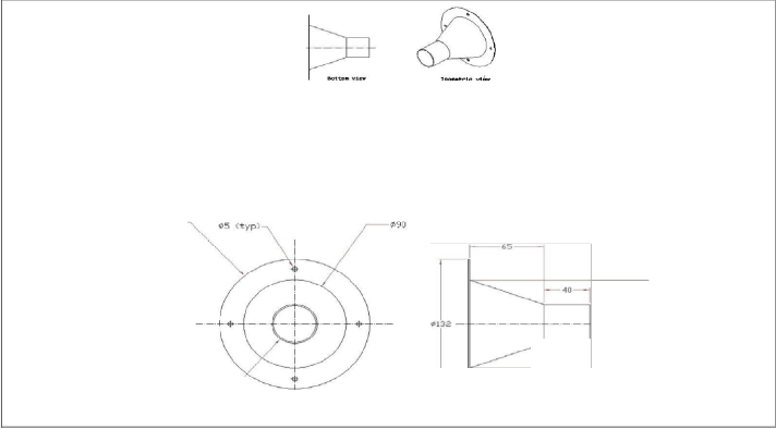
The matrix as discussed above is designed and assembled as per the dimensions given in the figure 3. The arrangement was provided within the system to fix the wire gauge of copper. It is designed in such a way so that the area of cross section at the point where the wire gauge is fitted is more than the area of cross-section of exhaust manifold of the engine. Wire gauge of mesh no. 20 is used and fitted with the help of nuts and bolts.
Engine Specifications are as follows: (a) Four stroke engine (4S)
RPM: 3 HP FUEL: PETROL
NUMBER OF CYLINDERS: SINGLE BORE: 70 mm
STROKE LENGTH: 70 mm
(b) Two stroke engine (2S)
SINGLE CYLINDER HORIZONTAL AIR COOLED PETROL
ENGINE.
MAXIMUM SPEED -3000 RPM
BRAKE HORSE POWER- 4.5HP.
2.2 Experimental Procedure
1. Connect the instrumentation power input plug to a 230 V,
50 Hz single phase AC supply. Now all the digital meters
namely, RPM indicator, temperature indicator display the
respective readings and also connect the inlet and outlet wa- ter connections to the exhaust gas calorie meter and engine.
2. Fill up the petrol to the fuel tank mounted side of the pan- el.
3. Check the lubricating oil level in the oil sump. Allow wa-
ter to the engine and calorie meter and adjust the flow rate.
4. Start the engine with the help of self start arrangement.
5. Allow the engine to stabilize the speed, i.e., 1500rpm or
2200 rpm by adjusting the accelerator.
6. Apply ¼ load, i.e. slowly vary the potentiometer.
7. Note down all the required parameters mentioned below: (a) Speed of the engine in rpm.
(b) Load from spring balance.
(c) Time taken for 10 cc of fuel consumption.
(d) Manometer readings.
(e) Different temperatures from temperature indicator.
8. Load the engine step by step with the use of field excita-
tion rheostat provided on the load bank such as, (a) ½ load
(b) ¾ load
(c) Full load
IJSER © 2013 http://www.ijser.org
International Journal of Scientific & Engineering Research, Volume 4, Issue 9, September-2013 2438
ISSN 2229-5518
9. Repeat the above procedure for different compression ra- tios. Similiarly, repeat the experimentation for the four stroke set up.
3 RESULTS AND DISCUSSION
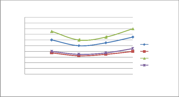
Emission parameters of a four stroke and two stroke S.I. en- gine with and without catalytic converter are studied by changing load and speed as shown in Fig. 6-13. By studying various graphs for carbon monoxide and hydrocarbon in vary- ing speed and load, the following results were obtained:
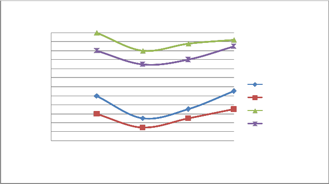
A) Figure 6 & 10 showed the effect of changing load on CO & HC percentage emission at 1500 rpm. It is clear from the figure that CO & HC emission at 0.25 load is somewhat higher than the moderate load (0.5 & 0.75 load) because the temperature outside the burning flame zone is much lower leading to for- mation of hydrocarbons also the air-fuel ratio is 10:1 leading to slow oxidation. As the load increases from 0.25 to 0.5 to 0.75, more amount of charge is supplied inside the cylinder and the oxidation process is accelerated. Finally, when load increases from 0.75 to 1, emission of CO and HC increases from 1.1% to
1.3% and 900 ppm to 1100 ppm respectively for four stroke engine. Similiarly, when load increases from 0.75 to 1, emis- sion of CO and HC increases from 1.3% to 1.6% and 1700 ppm to 1800 ppm respectively for two stroke engine. On repeating the same step using catalytic converter the emission of HC and CO are found to be lowered.
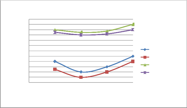
B) At varying increased load with increasing speed it is found that emission of CO & HC decreases as shown in figure 6-7 and 10-11 respectively.
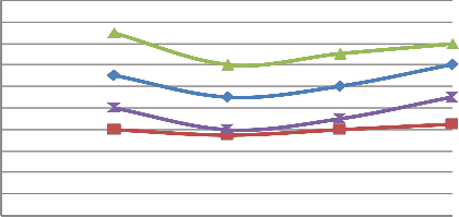
C) The emission of CO and HC decreases till the speed reaches to 2000 rpm, and on further increasing the speed the emission again increases as the port and spark timing did not match which results in incomplete combustion of fuel shown in fig- ure 8 & 12.
d)On repeating the above steps for 1500-2200 rpm using cata- lytic converter (Cu sieve) coated with copper nanoparticle, the emission of HC and CO are found to be lowered & more effi- cient than bulk copper.
4 CONCLUSION
The engine is designed to run at medium load (0.5 load) for a longer time due to less emission of HC and CO. At full load, emission of HC and CO is higher so it is not desirable to run engine at full load. The converter uses two different types of catalyst, reduction and oxidation catalyst. The idea behind the work is to create a structure that exposes the maximum sur- face area of catalyst to exhaust stream, also minimizing the amount of catalyst required. The exhaust gases pass through a bed of catalyst and the catalytic action takes place at surface of Cu which are porous and the the higher catalytic activity to- wards the oxidation of CO and HC could be due to the higher catalytic surface area of small nanoparticles. On comparision
of the graphs plotted, it can be clearly seen the CO and HC concentertion is more in two stroke engine than in four stroke spark ignition engine.
ACKNOWLEDGMENT
The authors wish to thank Rungta College of Engineering and
Technology, Raipur for their support.
REFERENCES
[1] Gilmour P S, Ziesenis A, Morrison E R, Vickers M A, Drost E M, Ford I, 2004, “Pulmonary and systemic effects of short term inhalation ex- posure to ultrafine carbon black particles”, Toxicological Applica- tions Pharmacology, 195, pp. 35–44.
[2] M. V., Twigg, 2006, “Roles of catalytic oxidation in control of vehicle exhaust emissions”, Catalysis Today, 117(4), pp. 407-418.
[3] Kishore K., Krishna M.V.S., 2008, “Performance of Copper Coated Spark Ignition Engine with Methanol Bended Gasoline with Catalytic Converter”, Journal of Scientific and Industrial Research, 67, pp.543-
548.
[4] Thakur Mukesh, Saikhedkar, N.K., 2012, “Recent trends in applica-
tion of nano-technology to automotive pollution control”, Interna- tional Science Congress.
[5] Thakur Mukesh, Saikhedkar, N.K., October 2012, “Role of metal nano-particles for automobile pollution control”, International Jour- nal of Engineering Research and Applications, 2(5), pp. 1947-1952.
[6] Feldheim D. L., Foss C. A., 2004, “Metal Nanoparticles: Synthesis, Characterization and Applications”, Appl. Phys. A Mater. Sci. Pro- cess. 78, pp.73.
[7] Schaper A. K, Hou H., Greiner A.,Schneider R., Philips F., 2004, “One Pot Synthesis of Copper Nanoparticles at Room Temperature and its Catalytic Activity”, Appl. Phys. A Mater. Sci. Process. , 78, pp.73.
[8] Thakur Mukesh, Saikhedkar, N.K., October 2012, “Atomic Activity of
Nano-particles for vehicular pollution control”, Abhinav Journal,
1(11), pp. 32-38.
[9] Pergolese B, Muniz-Miranda M. , Bigotto A., 2004, “SERS: a versatile tool in Chemical and Biochemical diagnostics”, J. Phys. Chem.,110 (92), pp.41.
[10] Thakur Mukesh, Saikhedkar, N.K., Sharma, Shilpa, 2013, “Rapid Control of Exhaust Emissions and Enhancement of Retention Time in the Catalytic Converter Using Nanosized Copper Metal Spray for Spark Ignition Engine”, Priyanka Research Journal, 3(1), pp. 1-10.
[11] Recent trends in application of nano-technology to automotive pollu- tion control”, International Science Congress.
[12] Flytzanis C. J., 2005, “Nonlinear optics in Mesoscopic Composite materials”, Physics B, 38 , pp.661.
[13] M. SAMIM, N. K. KAUSHIK, A. MAITRA, 2007, “Effect of Size of Copper Nanoparticles on its Catalytic Behaviour in Ullman Reac- tion”, Bull. Mater. Sci., 30 (5), pp.535-540.
[14] Huynh W., U, Dittmer J., Libby William C., Whiting, G. L , Alvisatos A .Paul , 2003, “Shape control and applications of nanocrystals”, Adv. Funct. Mater., 13, pp.73.
[15] Sharma R. K., Sharma P., Maitra A. N., 2003, “Metal nanoparticles with high catalytic activity in degradation of methyl orange: An elec- tron relay effect”, J. Colloid. Sci. 265, pp.134.
[16] Thakur Mukesh, Saikhedkar, N.K., 2013, “Rapid Control of Exhaust Emissions and Enhancement of Retention Time for Four Stroke En- gine Using Nano-sized Copper Metal Spray”, International Journal of Science, Engineering and Research, 4(1).
IJSER © 2013 http://www.ijser.org
International Journal of Scientific & Engineering Research, Volume 4, Issue 9, September-2013
ISSN 2229-5518
2439
FIGURE CAPTIONS:
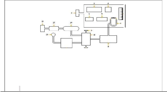
l)FIGUREl
FI GU RE - 1
a. AIR SUCTION BOX
9. V4R1ABLE cmRESSIOIN
RA.TIO AD..J ECTER
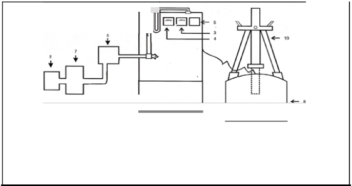
2) FIGURE 2
1 ll1
1. Burret
2. Manometer
3. Voltmeter
4. Ammeter
5. Temperature Indicator
6. En·gine
7. Calorimeter
.a. Camtytfc Converter
·9. Water Rheostat
10. Loading Assembly
IJSER lb)2013
International Journal of Scientific & Engineering Research, Volume 4, Issue 9, September-2013
ISSN 2229-5518
FIGURE3:
2440
2L2
I,"b
LJ 65
Ef j
- 33-
----------
----------- 1------ 40 -
----------
-1 t-------- ------+
101 ;V 33 -·-·- --·-·-·-·-· --------- ------- -- -E{ - cs0
_I
Ef j
./'./'
. './'
./'
./'/'
./'

FIGURE4:
--I
13a-- tI Et
!11132
-I·- i
- T--'_j.
/
•o _/
- ,-J_
IJSER lb)2013
International Journal of Scientific & Engineering Research, Volume 4, Issue 9, September-2013 2441
ISSN 2229-5518
FIGURE 5:
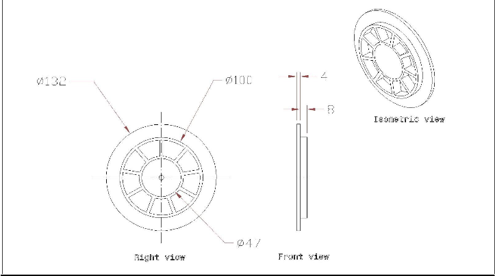
FIGURE 6: VARIATION OF CO WITH LOAD AT 1500 RPM
IJSER © 2013 http://www.ijser.org
International Journal of Scientific & Engineering Research, Volume 4, Issue 9, September-2013 2442
ISSN 2229-5518
2
1.8
1.6
1.4
1.2
1
0.8
0.6
0.4
0.2
0
CO %WoCC(4S) CO % WCC(4S) CO %WoCC(2S) CO % WCC(2S)
0 0.25 0.5 0.75 1
Load
![]()
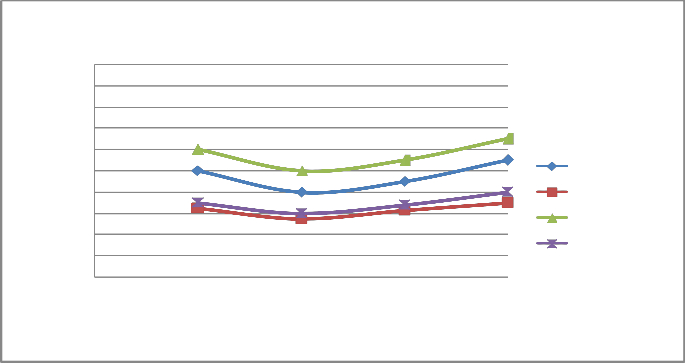
FIGURE 7: VARIATION OF CO WITH LOAD AT 1800 RPM
2
1.8
1.6
1.4
1.2
1
0.8
0.6
0.4
0.2
0
CO %WoCC(4S) CO % WCC(4S) CO %WoCC(2S) CO % WCC(2S)
0 0.25 0.5 0.75 1
Load
![]()
IJSER © 2013 http://www.ijser.org
International Journal of Scientific & Engineering Research, Volume 4, Issue 9, September-2013 2443
ISSN 2229-5518
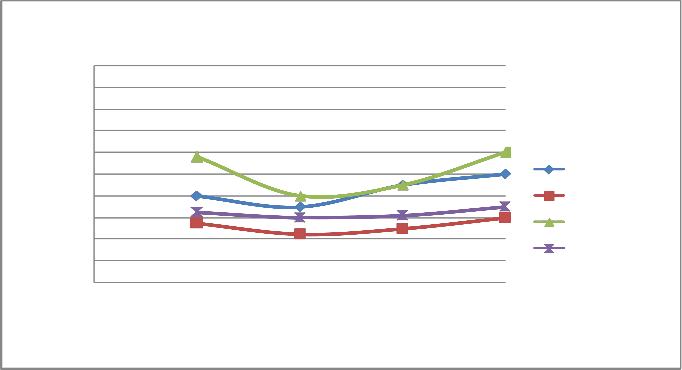
FIGURE 8: VARIATION OF LOAD WITH CO AT SPEED OF 2000 RPM
2
1.8
1.6
1.4
1.2
1
0.8
0.6
0.4
0.2
0
CO %WoCC(4S) CO % WCC(4S) CO %WoCC(2S) CO % WCC(2S)
0 0.25 0.5 0.75 1
Load
![]()
FIGURE 9: VARIATION OF LOAD WITH CO AT SPEED OF 2200 RPM
2
1.8
1.6
1.4
1.2
1
0.8
0.6
0.4
0.2
0
![]()
![]()
CO %WoCC(4S) CO % WCC(4S)
![]() CO %WoCC(2S)
CO %WoCC(2S)
![]()
CO % WCC(2S)
0 0.25 0.5 0.75 1
Load
![]()
IJSER © 2013 http://www.ijser.org
International Journal of Scientific & Engineering Research, Volume 4, Issue 9, September-2013 2444
ISSN 2229-5518
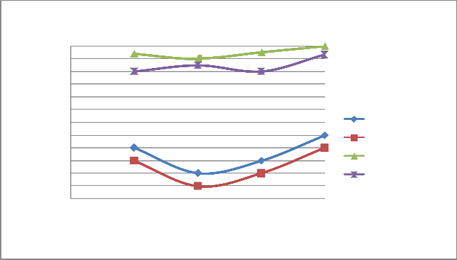
FIGURE 10: VARIATION OF HC WITH LOAD AT 1500 RPM
1800
1700
1600
1500
1400
1300
1200
1100
1000
900
800
700
600
HC PPM WoCC(4S) HC PPM WCC(4S) HC PPM WoCC(2S) HC PPM WCC(2S)
0 0.25 0.5 0.75 1
Load
![]()
FIGURE 11: VARIATION OF HC WITH LOAD AT 1800 RPM
IJSER © 2013 http://www.ijser.org
International Journal of Scientific & Engineering Research, Volume 4, Issue 9, September-2013 2445
ISSN 2229-5518
1800
1700
1600
1500
1400
1300
1200
1100
1000
900
800
700
600
HC PPM WoCC(4S) HC PPM WCC(4S) HC PPM WoCC(2S) HC PPM WCC(2S)
0 0.25 0.5 0.75 1
Load
![]()
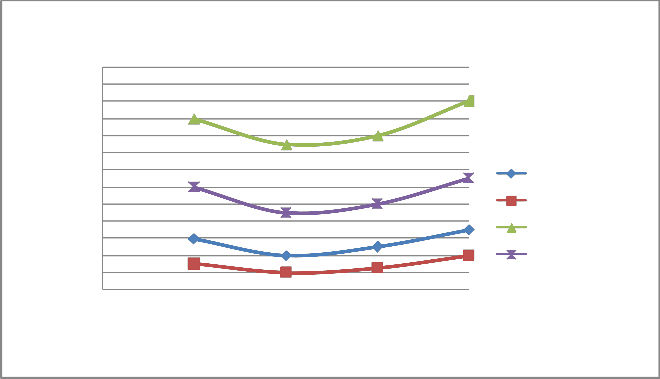
FIGURE 12: VARIATION OF HC WITH LOAD AT 2000 RPM
1800
1700
1600
1500
1400
1300
1200
1100
1000
900
800
700
600
500
HC PPM WoCC(4S) HC PPM WCC(4S) HC PPM WoCC(2S) HC PPM WCC(2S)
0 0.25 0.5 0.75 1
Load
![]()
FIGURE 13: VARIATION OF CO WITH LOAD AT 2200 RPM
IJSER © 2013 http://www.ijser.org
International Journal of Scientific & Engineering Research, Volume 4, Issue 9, September-2013 2446
ISSN 2229-5518
1800
1700
1600
1500
1400
1300
1200
1100
1000
900
800
700
600
HC PPM WoCC(4S) HC PPM WCC(4S) HC PPM WoCC(2S) HC PPM WCC(2S)
0 0.25 0.5 0.75 1
Load
![]()
IJSER © 2013 http://www.ijser.org