Inte rnatio nal Jo urnal o f Sc ie ntific & Eng inee ring Re se arc h, Vo lume 3, Issue 2, February -2012 1
ISS N 2229-5518
Comparision of Steering Geometry Parameters of
Front Suspension of Automobile
P. N. Belkhode, A. M. Mahalle, P. P. Holay
Abstract— Paper details the comparison of steering geometry parameters such as kingpin inclination angle, caster angle, camber angle, toe angle calculated from experimental observations, experimental data based model and artif icial neural netw ork theory. New techniques
present the prediction of vehicle perf ormance from the point of view of steering perf ormance and comparison of steering perf ormance of other vehicles.
Inde x Terms— Artif icial Neural Netw ork, Automobile, Co mparison, Experimental, Suspension, Steering, Vehicle.
—————————— ——————————
1 INTRODUCTION
HE Vehicle presents major challenges in terms of servicing and maintenance. Worn suspension bushings causes i n-
consistency in steering parameters. Steering geometry is
very sensitive to even slightest distortions in bushes of suspen- sion joints.
Steering performance parameters kingpin angle, caster angle,
camber angle, toe angle, scrub radius, toe in and toe out of front suspension of vehicle are determined based on experi- mental observations, data based model and artificial neural network is compared. New techniques present the prediction of vehicle performance from the point of view of steering per- formance and comparison of steering performance of other vehicles.
Presently paper details the comparison of steering geometry
parameters such as kingpin inclination angle, caster angle,
camber angle, toe angle calculated from experimental observa- tions, experimental data based model and artificial neural network theory.
2 FRONT SUS P ENS ION
2.1 Steering Geometry
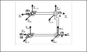
The six included angles of the 3D front suspension mechan- ism, one at each revolute joints and two at each spherical joints of this four bar chain, position of kingpin axis is determined. Steering performance depends on the position of kingpin axis. Depending on the position of Kingpin axis, Caster angle, Camber angle, Kingpin angle and toe angle of four wheel ve- hicle are decided.
Joint O1 and O2 are revolute joints and joints A and B are Spherical joints as shown in Figure 1. The relative orientation of two links connected at joint can be decided in terms of magnitudes of included angles which in turn can be measured by potentiometer and associated electronic instrumentation. Six potentiometers are located at four joints (two spherical and two revolute) of the RSSR mechanism. At revolute joints O1 & O2 the one included angle each of these joints and at spherical joints A & B the two included angles at each of these joints.
Fig. 1. : RSSR - Rev olute Spherical Spherical Rev olute
2.2 Steering Parameters
• Kingpin axis: The steer angle is achieved by rotation of the wheel about a steer rotation axis. This axis is kingpin axis is shown in figure.
• Kingpin inclination angle: Angle in front elevation between the steering axis and the vertical.
• Caster angle: angle in side elevation between the steering axis and the vertical.
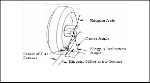
• Camber angle: Inclination of the wheel plane to the vertical
Fig. 2. : Front Sus pens ion of an Automobile
IJSER © 2012
http :// www.ijser.org
Inte rnatio nal Jo urnal o f Sc ie ntific & Eng inee ring Re se arc h, Vo lume 3, Issue 2, February -2012 2
ISS N 2229-5518
3. For mulation of an Experimental D ata B ased
Model
3.1 Identification of Physi cal Quantities affecting Fr ont
Suspen sion Geometry
The variables affecting the vehicle performance in the context of phenomena of steering are given below.
TABLE 1
INDEPENDENT AND DEPENDENT VARIBLES
Indepe nde nt Variables | De pe nde nt Variables |
1. Length of Upper control arm | 1. Kingpin angle |
2. Length of Low er control arm | 2. Camber angle |
3. Length of Knuckle arm | 3. Caster angle |
4. Length of Fixed link | 4. Toe angle |
5. Dia meter of w heel | 5. Toe in |
6. Mass of w heel | 6. Toe out |
7. Braker Height | 7. Scrub radius |
8. Braker Width | |
9. Wheel linear velocity | |
10. Operational time | |
11. Acceleration due to gravity | |
12. Clearance at spherical joint A | |
13. Clearance at spherical joint B | |
14. Clearance at revolute joint O1 | |
15. Clearance at revolute joint O2 | |
16. Lateral displacement | |
17. Spindle length | |
TABLE 2
PROCESS VARIBLES
Cs = f (Ua, La, Ka, Fi, Dw, Wt, Bh, Bw, Vt, t, g, Co1, Co2, Ca, Cb, Ld, Sl) -----------(1)
General form can be defined as
(Ua, La, Ka, Fi, Dw, Wt, Bh, Bw, Vt, t, g, Co1, Co2, Ca, Cb,
Ld, Sl, Kgp, Cs, Cm, Ta, Ti, To, Sr) = 0
21 dimensionless terms
(1,2,3,4,5,6,7,8, 9, 10, 11, 12, 13, 14, 15, 16,
17,18,19, 20, 21) = 0
Choosing Ua, Vt and Wt as repeating variables
1 = La / Ua
Similarly for other terms are evaluate and dimensionless equations are formed
Caster angle:
Cs = f (La x Ka x Fi / Ua3 , Dw / Ua , Bh x Bw / Ua 2 , Vt x t / Ua , Ua x g / Vt2, Co1 x C02 x Ca x Cb / Ua 4, Ld x Sl / Ua 2 )
3.2 Deduction o f Generalized Experimental Data Based
Models:
Classical experimentation was planned and carried out on the front suspension of an automobile for predicating steering behavior, to establish empirical relationships among the dependent terms and independent terms. The dependent and independent variables are defined in the Table 1. The dependent dimensionless ratios and Independent dimensionless ratios are as shown below.
TABLE 3
DIMENSIONLESS PI T ERMS
1
M, L and T are the symbols for mass, length and time respectively using the dimensionless .
Caster angle
3.3 Formulation of Experimental Data Based Model
Each dependent term is the function of the available inde- pendent terms,
Cs = f(1, 2, 3, 4, 5, 6, 7 ) Where,
Cs = D1 , dependent pi term
Model of dependent pi term D1
Caster angle, Cs = k3 x (1)a3 x (2)b3 x (3 )c3 x (4)d3 x (5)e3 x (6 )f3
x (7)g3
The values of exponents a 1, b1, c1, d1, e1, f1, g1 are established independently at a time, on the basic of data collected through
classical experimentation. From these models values of all de- pendent pi terms are computed.
Cs = k1 x (1)a1 x (2 )b1 x (3)c1 x (4 )d1 x (5)e1 x (6)f1 x (7)g1 (1)
Z = a + bX + cY +dZ+…… (2)
IJSER © 2012
http :// www.ijser.org
Inte rnatio nal Jo urnal o f Sc ie ntific & Eng inee ring Re se arc h, Vo lume 3, Issue 2, February -2012 3
ISS N 2229-5518
The equation 1 can be brought in the form of equation 2 by taking log on both sides.
3.4 Model Formulation:
Model of dependent pi term D1 for kingpin angle
Cs = k1 x (1)a1 x (2 )b1 x (3)c1 x (4 )d1 x (5)e1 x (6)f1 x (7)g1
D1 = k1 x (1)a 1 x (2)b1 x (3)c1 x (4)d1 x (5)e1 x (6)f1 x (7 )g1
Taking log on the both sides of equation for D1 ,getting eight unknown terms in the equations,
Log D1 = log k1+ a1log 1+ b1log 2+ c1log 3 + d1log 4 + e1log
5 + f1log 6 + g1log 7 -------(3) Let,
Z1= log D1, K1 = log k1, A = log 1, B = log 2
C = log 3, D = log 4 , E = log 5, F = log 6
G = log 7
Putting the values in equations 3, the same can be written as
Z1 = K1+ a1 A + b1 B + c1 C + d1 D + e1 E + f1 F + g1G (4)
X1 matrix with K1 and indices a1, b1, c1, d1, e1, f1, g1 follows
Cs = 1.020939 x 10 9 (1)104.05 (2)61.813(3)0.0384(4)65.836(5) -0.236(6)
7.302(7)0.88782
TABLE 5
VALUES OF DEPENDENT PI TERMS COMPUT ED BY EXPERIMENTAL
OBSERVAT IONS, EXPERIMENTAL DATA BASED MODELS AND ANN SI- MULAT ION
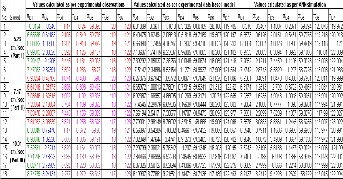
5 CONCLUSION
Table shows the steering performance parameters computed by experimental observations, experimental data based model and ANN simulation
Thus corresponding to the dependent pi terms, models are
REFERENCES
-----(9)
formulated from the set of observed data for the response of caster angle. From these models values of the dependent pi terms are computed. The observed and computed values of the dependent pi terms are compared by calculating their mean values. In order to check the accuracy of the predicted / computed values of the dependent pi terms, error is worked out.
4 Analysi s o f Performance of the Model
The models have been formulated mathematically. An a p- proximate generalized experimental data based models are evolved for predicating the Steering Behavior.
This includes application of Dimensional Analysis is quite simple way in which a given test can be made compact in op- erating plan. In this experimentation we may not be able to recognize all the variables that influence a test, but we should realize that they and their dimensional equation have reality whether or not it is apparent.
The indices of the model are the indicators of how the phen o- menon is getting affected because of the interaction of various independent pi terms in the models. The influence of indices of the various independent pi terms on each dependent pi term is discussed below.
5. Comparison of computed values of experimental obse r- vation, experimental data based model and ANN simula- tion.
The comparison of the steering performance parameters by
above three approaches is given below in Table 5
[1] T. D. Gillespie, ―Fundamentals of Vehicle Dynamics ‖, Society of
Automotive Engineers. Inc Warrendale, PA – 1992.
[2] Suh and Redcliff, ― Kinematics Design of Mechanisms ‖, John Wiley
and Sons, New York, 1978.
[3] M. Modak et all, ―Electronic Measurements System for Torsionally Flexible Clutch‖, Vibro engineering ‗98‘, IFToMM Speciality Symp o- sium University of Kanvaus, Lithunta.
[4] Denavit and Hertenberg, ―A Kinematic Notation for Lower Pair Me-
chanisms Based on Matrices ‖, A.S.M.E. transaction, Journal of A p- plied Mechanics June 1955, PP 215-221.
[5] Prof. Dr. Georg Rill, ―Vehicle Dynamics‖, Fachhochschule Regens-
burg, University of Applied Sciences, Hochschule for Technik Wrt- schaft Soziales.
[6] K. S. Fu, R. C. Gonzalez, C. C. G. Lee, ―Robotics: Control Sensing,
Vision and Intelligence‖, Mc Graw Hill Internation Edition, Signa- pore.
IJSER © 2012
http :// www.ijser.org