International Journal of Scientific & Engineering Research, Volume 4, Issue 12, December-2013 1535
ISSN 2229-5518
Ambika R., Rashmi N., Paul N. S. Augustus, Muneeb U. Shariff
Abstract− In this paper we aim to highlight the role of RFID and GSM technologies in obtaining and processing relevant information from public infrastructure systems in real time. The system that is described here is only the first step towards a practical method to ease the tariff collection process.
Index Terms− AT commands − Attention Commands, Database, GSM − Global System for Mobile Communication, RFID − Radio Frequency Identification technology, RTC – Real Time Clock, SIM − Subscriber Identity Module
—————————— ——————————
n this project we aim to provide an alternate means of
collecting tariff for every bus commuter. Transportation
has always been an important aspect of every major civilization in history which has evolved into more complex
forms, whether it was logistics or passengers. In the present
RFID tags are used to emit the radio frequency electromagnetic waves containing a unique ID number which is provided to a commuter of the bus service. A postpaid account in his/her name will be created by the
metropolitan bus transport organization and stored in the
IJSER
day India, one in four workers commute via the public bus
transport. Most of the time, the problem we face while
commuting is tendering exact change for a ticket or paying extra for covering a particular distance. What if there was no need for issuing tickets? What if each commuter had unique ID to which the tariff for the distance he/she travelled could be billed? By creating a RFID system in conjunction with a central database to manage real time information, we can obtain accurate tariffs for every commuter’s trip. Thus, the main concept of this paper is to design a bus transport tariff collection system which is centralized, so that the process becomes paperless and human errata is removed.
————————————————
• Muneeb Shariff is a graduate student from the Electronics & Communication Dept. in B.M.S. Institute of Technology, India.
E-mail: muneebullashariff@gmail.com
database, which will be accessed by his pre-assigned Identification number only. Once the person enters the bus his/her unique ID number will be detected and sent along with the current distance and time to the central operator/database. Similarly, when the person exits the bus his/her ID number will be detected and sent along with the current distance and time to the central operator/database. In the central database/operator, this information is used to calculate the tariff for the commuter’s trip and is stored on the database.
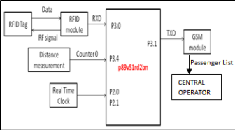
Fig. 1 Setup of Bus Module
IJSER © 2013 http://www.ijser.org
International Journal of Scientific & Engineering Research, Volume 4, Issue 12, December-2013 1536
ISSN 2229-5518
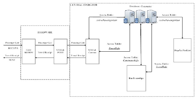
Fig. 2 Setup of central operator
IJSER
When the passenger walks into the bus he scans his
RFID tag. The unique ID present into the RFID tag will be recorded by the RFID module which is connected to the serial-receive pin P3.0 of the microcontroller. (depicted in Fig. 1)
At this time the current distance is calculated by using
the formula Distance travelled= {circumference of the wheel} *
{number of revolutions the wheel makes}. Circumference of the
wheel is a constant, while the number of revolutions the bus makes is a variable factor, which is accurately counted by using the reed switch circuit. The pin P3.4 of the microcontroller is configured as a counter as a result the registers TH0 and TL0 will contain the number of revolutions the bus wheel has made. Also, the time of entry of the passenger is recorded using the RTC, which generates the accurate time.
When the passenger walks out of the bus he again scans his tag and at this time the current distance and the time will be tagged with the RFID. This information is sent from the microcontroller to the host computer through the GSM modem via messages. Each message contains the details of
6 passengers utilizing all 160 characters of a message.
The incoming data is read and extracted by a program. If
the passenger’s ID is not present in the
“ActivePassengerList” table of the database then an entry is
made in the same table, otherwise, the corresponding entry
is deleted in the “ActivePassengerList” table and a new entry consisting of the distance travelled, the equivalent tariff and the time of entry and exit is made in the “TravelInfo” table. Only the “ActivePassengerList” and “TravelInfo” tables are accessed in the database by this program. (Fig. 2)
Another program is used to add, view and modify
commuter information, hence, it only accesses the “CommuterInfo” and “TravelInfo” tables present in the database.
Finally, another program is used display all the passengers currently commuting in a bus. Hence, it only accesses the “ActivePassengerList” table.
The “BusTransOpr” program is used to add, view and
modify commuter information, hence, it only accesses the
“CommuterInfo” and “TravelInfo” tables present in the database.
The “DisActPasList” program is used display all passengers currently commuting in a bus. Hence, it only accesses the “ActivePassengerList” table.
IJSER © 2013 http://www.ijser.org
International Journal of Scientific & Engineering Research, Volume 4, Issue 12, December-2013 1537
ISSN 2229-5518
Fig. 3 Logic execution of bus module
3.2 Central Operator
The basic reed switch consists of two identical flattened ferromagnetic reeds, sealed in a dry inert-gas atmosphere within a glass capsule, thereby protecting the contact from contamination. The reeds are sealed in the capsule in cantilever form so that their free ends overlap and are separated by a small air gap.
When a magnetic force is generated parallel to the reed switch, the reeds become flux carriers in the magnetic circuit. The overlapping ends of the reeds become opposite magnetic poles, which attract each other. If the magnetic force between the poles is strong enough to overcome the restoring force of the reeds, the reeds will be drawn together.
Distance travelled= {circumference of the wheel} * {number of revolutions the wheel makes}
1. Circumference of the wheel = 2*PI*R
R= radius of the wheel
IJSE2. To determineRthe number of revolutions
Whenever the magnet, fixed to the shaft of the wheel,
comes within the vicinity of the reed switch, the switch closes due to the magnetic fields emitted by the magnet. Hence, the output of the above circuit will be logic ‘1’ or 5 volts.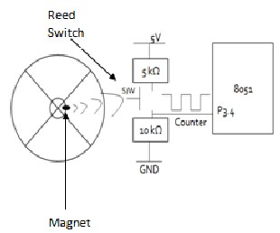
Fig. 4 Logic execution of Central Operator
Fig. 5 Reed switch circuit mechanism
IJSER © 2013 http://www.ijser.org
International Journal of Scientific & Engineering Research, Volume 4, Issue 12, December-2013 1538
ISSN 2229-5518
When the magnet moves away from the reed switch the magnetic fields doesn’t have an influence on the switch as a
result it opens and forces the output to be logic ‘0’ or 0 volts.
In order to count the number of times the reed switch
closes, we are configuring the microcontroller as a counter. Whenever the input to the pin P3.4, configured as counter, is logic ‘1’, increments by 1. Thus, the data present in the registers TH0 and TL0 gives the number of revolutions. Advantages in using reed switches −
They are hermetically sealed in glass environment, free
from contamination, and are safe to use in harsh
industrial and explosive environments.
No need to energize the transmitter as it is a magnet.
Resistant to shock and vibration
Can be used with inexpensive magnets
Very sensitive to magnetic fields
AT commands are instructions that are used to operate the
GSM modem. Send (AT+CMGS), read (AT+CMGR), write
When the passenger enters the bus his Identification number, time and the current distance is taken and the details of each passenger is stored and a sum of 6 passengers information is sent through the SIM 300 GSM modem.
Thus, the output of the bus module is as shown in the figure 6. The output is just to verify that the data from the bus is successfully reached the central database or not.
Once the data is received at the database end, the received passengers list is as shown in figure 7. This received list is then made to pass through the serial port of the database wherein the data in the list is extracted and updated.
The extracted passenger information is as shown in figure 8. Thus, the data from the bus module is taken successfully and used for calculating the tariff.
The main objective of the project was to make tariff
collection paperless and centralized, so that any errata that
IJSER
(AT+CMGW) or delete (AT+CMGD) SMS messages are a
few of the commands used in this project.
The following are the AT Commands and sequence of events performed for sending text message to a mobile phone through the GSM Modem interfaced with microcontroller −
1. First select the text mode for SMS by sending the
following AT Command to GSM Modem : AT+CMGF = 1 . This command configures the GSM modem in text mode.
2. Send the following AT Command for sending SMS message in text mode along with mobile number to the GSM Modem : AT+CMGS =+923005281046 . This command sends the mobile number of the recipient mobile to the GSM modem.
3. Send the text message string ("hello!") to the GSM Modem.
4. Send ASCII code for CTRL+Z i.e., 0x1A to GSM Modem to transmit the message to mobile phone. After message string has been sent to the modem, send CTRL+Z to the micro-controller, which is equivalent to 0x1A (ASCII value). Every AT command is followed by i.e. carriage return and line feed you are giving line feed first and carriage return after that. ("\r" stands for carriage return)
may occur in the currently employed process can be overcome. This system maintains a central database were all information is stored, such as history of a particular commuter’s trips. The objectives of our project that have been achieved are as follows:
• To realize a paperless and centralized tariff system for
bus commuters.
• To remove the hassles of tendering exact change for
ticket.
• To charge commuters for the distance they have travelled.
• To remove any human error or erratum that may occur.
• To create an accurate record of the revenue collected.
IJSER © 2013 http://www.ijser.org
International Journal of Scientific & Engineering Research, Volume 4, Issue 12, December-2013 1539
ISSN 2229-5518
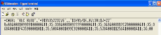
Fig. 6 Output of Bus Module
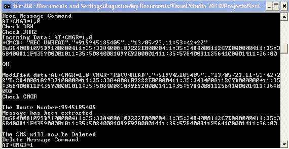
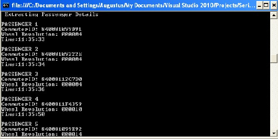
Fig. 7 ReceivedIPassengJer List at the CeSntral Operator ER
Fig. 8 Extracted Passenger Information
IJSER © 2013 http://www.ijser.org
International Journal of Scientific & Engineering Research, Volume 4, Issue 12, December-2013 1540
ISSN 2229-5518
[1] Roy Want, “An Introduction to RFID Technology,” IEEE CS and IEEE ComSoc, Vol. 5, No. 1, Santa Clara, 2006, PP. 25-33.
[2] Hyun-Seok Kim, Jung-Hyun Oh, Jin-Young Choi and Jin-
Woo Kim, “The Vulnerabilities Analysis and Design of the Security Protocol for RFID System,” Proceedings of the Sixth IEEE International Conference on Computer and Information Technology, Seoul, 2006, p.152.
[3] Density measuring system using magnetically actuated
reed switch, published in Instrumentation Control and Automation (ICA), 2011 2nd International Conference on 15-17 Nov. 2011
[4] Magnetic and mechanical design of ultraminiature reed
switches, published in Components, Hybrids, and
Manufacturing Technology, IEEE Transactions on (Volume:15 , Issue: 2 ) on Apr 1992
[5] Power Aware Automatic Microcontroller Based Smart, College Electric Bell System with Time Display, published in, MEMS, NANO, and Smart Systems (ICMENS), 2009 Fifth International Conference
on 28-30 Dec. 2009
[6] Identifying objects using RF transmitters and receivers, and retrieving data using GSM, published in,
Computer and Automation Engineering (ICCAE), 2010
The 2nd International Conference on 26-28 Feb. 2010 [7] Automation of attendance system using RFID,
biometrics, GSM Modem with .Net framework, published in, Multimedia Technology (ICMT), 2011
International Conference on 26-28 July 2011
[ 8]Radio Frequency Identification (RFID) Based Toll Collection System, published in, Computational Intelligence, Communication Systems and Networks (CICSyN), 2011 Third International Conference
on 26-28 July 2011
IJSER © 2013 http://www.ijser.org