Fig. 1. The closed loop system block diagram.
International Journal of Scientific & Engineering Research, Volume 2, Issue 3, March-2011 1
ISSN 2229-5518
Calculation of PID Controller Parameters for
Unstable First Order Time Delay Systems
Hamideh Hamidian, Ali Akbar Jalali
Abstract— In this paper, a numerical approach for the fractional order proportional-integral-derivative controller (FO-PID) design for the unstable first order time delay system is proposed. The controller design is based on the system time delay. In order to obtain the relation between the controller parameters and the time delay, for several amounts of the plant time delay and the fractional derivative and integral orders, the ranges of stabilizing controller parameters are determined. First, for a typical time delay plant and the fractional order controller, the D-decomposition technique is used to plot the stability region(s). The controller derivative gain has been considered as one. By changing the fractional derivative and integral orders, a small amount in each stage, some ranges of proportional and integral gains are achieved which stabilize the system, independent of
the fractional 'A , � orders. Therefore a set of different controllers for any specified time delay system is obtained. This trend for
several various systems with different values of time delay has been done and the proportional and integral gains of the stabilizing controller have been calculated. Then we have fitted these values to the exponential functions and the proportional and integral gains have been obtained in terms of the system time delay. Using these relations, we can specify some ranges of the proportional and integral gains and obtain a set of stabilizing controllers for any given system with certain time delay. In these relations, fractional derivative and integral orders haven’t part, and therefore can be applied to any fractional order
controller design (for 0.1 'A ,� 0.9
). Thus we have reached a numerical approach from the graphical D-decomposition
method. In this method, there is freedom in choosing the values of 'A and � (they can fall in the range of [0.1, 0.9] ), and there is no need to plot the stability boundaries and check the different regions to determine the stable one. This numerical method does not offer the complete set of the stabilizing controllers. W henever the system time delay is more, the specified range of
proportional and integral gains will be smaller. In other words, the extent of obtained stability region is inversely proportional to the system time delay. Finally, the introduced numerical approach is used for stabilizing an unstable first order time delay system.
Index Terms—Fractional order PID controller, numerical approach, time delay.
—————————— • ——————————
LTHOUGH great advances have been achieved in the control science, the proportional-integral- derivative controller is still the most used industrial
controller.
According to the Japan Electric Measuring Instrument
Manufacturers’ Association in 1989, PID controller is used
in more than 90% of control loops [1], [2]. As an example
for the the application of PID controllers in industry, slow
industrial processes can be pointed, low percentage over-
shoot and small settling time can be obtained by using
this controller [1]. Widespread application of the PID con-
troller is due to the simple and implementable structure and its robust performance in the wide range of the work- ing conditions [3], [4]. This controller provides feedback, it has the ability to eliminate steady-state offsets through
integral action, and it can anticipate the future through derivative action. The mentioned benefits have caused widespread use of the PID controllers. The derivative action in the control loop will improve the damping, and therefore by accelerating the transient response, a higher proportional gain can be obtained. Precise attention must be paid to setting the derivative gain because it can ampl- ify high-frequency noise. In this paper, for the fractional order PID controller design, the derivative gain ( kd ) is set
1, that will result in design simplicity. Most available
commercial PID controllers have a limitation on the de-
rivative gain [2]. During the past half century, many theo- retical and industrial studies have been done in PID con- troller setting rules and stabilizing methods [3]. So far several different techniques have been proposed to obtain PID controller parameters and the research still continues to improve the system performance and increase the con- trol quality. Ziegler and Nichols in 1942 proposed a me- thod to set the PID controller parameters. Hagglund and Astrom in 1995, and Cheng- Ching in 1999, introduced other techniques [5]. By generalizing the derivative and integral orders, from the integer field to non-integer numbers, the fractional order PID controller is obtained. In fractional order PID controller design, there is more freedom in selecting the parameters and more flexibility in their setting . This is due to posse of choice -both integ- er and non-integer numbers- for integral and derivative orders. Therefore control requirements will be easier to comply [6], [7].
Before using the fractional order controllers in design, an introduction to fractional calculus is required. Over
300 years have passed since the fractional calculus has been introduced. The first time, calculus generalization to fractional, was proposed by Leibniz and Hopital for the first time and afterwards, the systematic studies in this field by many researchers such as Liouville (1832), Holmgren (1864) and Riemann (1953) were performed [8].
IJSER © 2011
2 International Journal of Scientific & Engineering Research, Volume 2, Issue 3, March-2011
ISSN 2229-5518
Fractional calculus is used in many fields such as electric- al transmission losses systems and the analysis of the me- chatronic systems. Some controller design techniques are based on the classic PID control theory generalization [7]. Due to the recent advances in the fractional calculus field and the emergence of fractance electrical element, the fractional order controller implementation has become
thod, the controller has been designed based on required maximum overshoot and the rise time. In the mentioned technique, the closed loop system characteristic equation is minimized in order to get an optimal set of the control- ler parameters [1]
One of the methods to obtain the complete set of stabi- lizing PID controllers is plotting the global stability re-
more feasible [6], [9], [10]. Consequently, fractional order
gions in the (k p ,ki ,kd )
-space, which is called the D-
PID controller analysis and synthesis have received more attention [11], [12], [13], [14], [15], [16]. Results obtained
from various articles published in this field, indicate that the fractional order PID controllers enhance the stability, performance and robustness of the feedback control sys- tem [6], [11], [12]. Maiti, Biswas and Konar [1] have signif- icantly reduced the overshoot percentage, the rise and settling times, compared to classic PID controller, using the fractional order PID controller. Applying the fraction- al order PID controller ( PI 'A D � ), the system dynamic cha- racteristics can be adjusted better [17]. Many dynamic processes can be described by a first order time delay transfer function [18]. The need to control time delay processes can be found in different industries such as roll- ing mills. Varying time delay process control becomes difficult using classical control methods [19]. Simple for- mulas are available for setting the PID controller parame- ters for the stable first order time delay system, but when the system is unstable, the problem will be more difficult and therefore the unstable systems control requires more attention. Many attempts have been made in field of their stabilization [20], [21], [22], [23], [24]. So far, various de- sign techniques have been suggested for the fractional order controller design [13], [14], [25], [26]. It has been shown that fractional order PID controllers have a better performance comparing to integer order ones, for both integer and fractional order control systems.
In the controller design for an unstable system, the most
decomposition technique [3], [4], [6], [8]. This technique is
used in both fractional and integer order systems analysis
and design.
Cheng and Hwang [6] has designed the fractional order
proportional - derivative controller to stabilize the unsta-
ble first order time delay system and D- decomposition
method has been used. The graphical D- decomposition
technique results for such systems are simple.
The D- decomposition technique can be used for frac-
tional order time delay systems and fractional order chaos systems. In this method, the stability region boundaries are obtained, which are described by real root boundary (RRB), infinite root boundary (IRB), and complex root
boundary (CRB). By crossing these boundaries in the (k p , ki , kd ) -space, several regions will be achieved. By choosing an arbitrary point from each region and check-
ing its stability, the region’s stability is tested. If the se- lected point is stable, the region including that point would be stable, and if the selected point is not stable then the region would be unstable. By obtaining the sta- bility boundaries and plotting the stability regions, a complete set of stabilizing fractional order controller pa- rameters is obtained. The mentioned algorithm is simple and effective.
2.2 The D-decomposition Technique
In general, the characteristic equation of the fractional order closed loop system is defined as
important design issue is stabilizing the closed-loop sys-
( ) qk
qk -1 q1
P s = pk s
pk -1 s
... p1 s
p0 .
(1)
tem [6]. As an example of previous research in stabilizing
the unstable processes, we can point to De Paor and
O’Malley research in 1989, which discussed unstable open
loop system stabilization with a PID or PD controller [23].
Hamaci [3] has concluded that fractional order PID con- troller has a better response than classic one. In this pa- per, a numerical method is introduced to design the frac- tional order controllers for any unstable first order system
with specified time delay.
In P parameter space, the boundaries between stable
and unstable regions are defined by three following parts:
Real root boundary (RRB): A real root crosses over the
imaginary axis at s=0. Thus the real root boundary is ob-
tained by setting s = 0 in (1). RRB is determined as p0 = 0 .
Complex root boundary (CRB): A pair of complex roots, cross over the imaginary axis at s = jro .
Infinite root boundary (IRB): An infinite real root
crosses over the imaginary axis at s = joo . Therefore IRB
line is obtained by putting
pk = 0 in (1). First, by using the
D-decomposition graphical method, stability boundaries
and then stability region(s), are obtained. RRB and IRB
lines are given by
2.1 A Review to Design Methods
RRB : ki = 0
(2)
Hamamci and Koksal [4] have designed the fractional
IRB : k
= 0 � 1 l .
(3)
order PD controller to stabilize the integration time delay system, which result that stability region extent is re-
d oo � 1
Then by writing k and k equations in terms of k , 'A ,
versed with the system time delay. Maiti, Biswas, and p i d
Konar, in 2008, could significantly reduce the overshoot percentage, the rise time, and the settling time by using fractional order PID controllers. They introduced PSO (particle swarm optimization) optimization technique for the fractional order PID controller design. In their me-
and � , the CRB curve equation is derived. The transfer
function of the plant and fractional order PID controller and closed-loop system characteristic equations have been given in (4), (5), and (6), respectively. Fig. 1 shows the block diagram of the closed loop system.
IJSER © 2011
International Journal of Scientific & Engineering Research, Volume 2, Issue 3, March -2011 3
ISSN 2229-5518
Fig. 1. The closed loop system block diagram.
G ( s) =
e-e s
![]()
s - 1
, = 1
(4)
C ( s ) = k p
![]()
ki
s'A
k s �
(5)
( ) = (
- 1) 'A
-e s (
'A ' A � ) = 0
P s s s e k p s ki
kd s (6)
CRB curve equations are given in (7).
CRB : P (ro; k ) = 0
A (ro ) B (ro ) - C (ro ) D (ro ) kd ( E (ro ) B (ro ) - F (ro ) D (ro ) ) l
(7)
CRB :
k p =

G (ro ) B (ro ) - D (ro ) H (ro )
-0.5 s
ki =
Where
C (ro )G (ro ) - A (ro ) H (ro ) kd (F ( ro ) G (ro ) - E (ro ) H (ro ) )

G (ro ) B (ro ) - D ( ro ) H ( ro )
Fig. 2. The stability region for the
PI 0.4 D0.7 controlle.
e
![]()
s - 1
plant and the
A (ro ) = ( cos ='A ro 'A
( sin ='A ro('A 1)
(8a)
2 2
) )
B (ro ) = (- sin roe )
C (ro ) = ( sin 'A ro'A - ( cos 'A ro( 'A 1)
(8b) (8c)
Two limited rectangles are selected from the stability region, one rectangle in the first quarter of the (k p ,ki ) -
plane and another one in the second quarter of the plane.![]()
![]()
2 2
) )
D (ro ) = (cos roe )
E (ro ) = -ro(' A � ) ( cos (roe ) .cos ('A � )
(8d)
sin (roe ) .sin ('A � ) (8e)
Fig. 3 shows two selected rectangles. Rectangle (1) which
includes positive values of the proportional and integral
gains is marked in light gray, and rectangular (2) which
2 2
) contains negative proportional gain and positive integral
F = ro( ' A � ) ( - cos (roe ) .sin ('A � ) sin (roe ) .cos ('A � )
(8f)
gain, is marked in dark gray. Two rectangles are chosen
2 2 so that the minimum value of
k is zero (means that rec-
) i
G (ro ) = (cos roe ) . cos 'A ro'A
(sin roe ) . sin 'A ro'A
(8g)![]()
( (
![]()
2 ) 2 )
H (ro ) = (cos roe ) .( sin ='A ro 'A - (sin roe ) .( cos 'A ro 'A
(8h)
tangles have been placed on the RRB line) and the mini-
mum value of k p is close to zero as much as possible.
Maximum value of the proportional gain in the second
2 2
) )
By plotting IRB and RRB lines and CRB curve in the ( k p ,ki ) -plane, for fixed kd , 'A , and � , as ro runs from
0 to oo , Stability regions are obtained [3], [4], [6], [8]. As- suming kd = 1 , the D-decomposition technique is used for various values of 'A , � and e , and stability regions are obtained by arbitrary selected test points. In this paper,
Nyquist stability test has been used to check the stability of the selected point of each region. The range of changes for 'A and � are considered between zero and 1.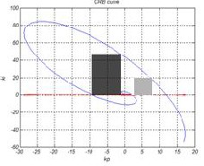
rectangle is selected near zero as much as possible.
To determine the relations between the controller para- meters with time delay system, the stability regions are
Fig. 3. Two selected rectangles, for the
e-0.5 s
![]()
s - 1
system,
determined using D-decomposition technique. In Fig. 2
e-0.5 s
which is controlled by the PI 0.4 D0.7 controller.
the stable region of
s - 1
plant with![]()
PI 0.4 D0.7 controller is
Considering the mentioned criteria for selecting two
marked in gray. Notice that the small region that includes small proportional and integral gains (near the origin) is
stability rectangles, for various amounts of the system
time delay, we have obtained the minimum and maxi-
not a part of the stability regions.
mum values of k p
and maximum value of ki . First, by
e-0.1s
considering different PI 'A D �
controllers (0 'A , � 1)
![]()
for
s - 1
IJSER © 2011
4 International Journal of Scientific & Engineering Research, Volume 2, Issue 3, March-2011
ISSN 2229-5518
system, we choose two mentioned stability rectangles. In both rectangles, the maximum and minimum value of the proportional gain and the maximum value of the integral
The upper curve is obtained from the maximum propor- tional gain values fitting, and the underlying curve is ob- tained from fitting the integral gain minimum values.
gain are shown with
k , k and
k ,respectively. By
These curves should not exceed r , l
pmax
pmin
imax
k pmin k pma x .
changing the fractional derivative and integral orders, the position of the rectangles on the (k p ,ki ) -plane will change,
but in all, some values of k p and ki are the same.
This procedure is performed in two stages. First, rectan-
gle 1 is considered. For e = 0.1
, considering several con-
trollers with different fractional orders, it can be observed that if the controller proportional gain is selected between
15 and 40 and the integral gain between zero and 25, for any fractional derivative and integral orders between 0.1 and 0.9, the controller will stabilize the system. By chang- ing the value of the system time delay, this process is re- peated and for each system, some ranges of k p and ki are determined, any arbitrary controller with these obtained parameters (where the fractional orders 'A and � are be- tween 0.1 and 0.9) can stabilize the system. For some first order systems with the time delay e , the obtained ranges of stabilizing controller parameters are given in Table 1.
Fig. 4. The selected ranges for the proportional gain and the fitting results.
Maximum proportional gain in rectangle 1 is fitted to
These
k p and ki
values belong to rectangle 1 within the
a.e-be
c.e- de , such that the resulting exponential function
stable region and have been obtained independently of
the fractional derivative and integral orders. To study
time delay effect on the range of controller parameters, in each step e has been changed slightly (0.05).
To obtain the proportional and integral gains range in-
is close to the maximum value of k p as much as possible (minimize the fitting error), also the fitting result should be located between the selected minimum and maximum proportional gain values. This fitting result is
76 e-10.8e
16 e-1.8e . Similarly, the minimum proportional
dependent of fractional derivative and integral orders, we
gain in rectangle 1, is fitted to 45 e-15e
8 e-1.8e . The maxi-
consider different values of 'A and � , which change
mum integral gain which is selected from rectangle 1 is
slightly in each step (0.05). By increasing the system time
fitted to
60.1e-13e
8 e-2.5e . According to these fitting re-
delay, the values of the minimum and maximum propor-
sults, for FO_PID controller design for the system with
tional gain and maximum selected value of the integral
the time delay e ( 0.1 e
1 ), selecting the proportional
gain become smaller, Table 1 also confirms this reduction.
Table 1. The stabilizing parameters ranges in rec-
gain from (9), the integral gain from (10), and the frac- tional orders from the given range in (11), the closed-loop
tangle 1(for any arbitrary PI 'A D �
control-
ler (0.1
'A ,�
0.9 ) )
system would be stable.
k = a.e-be
c.e- de ,
0 a
d = 1.8
60l
(9)
k a e-be
c e- de
13 b
i =
0.1
. . ,
0 c 8
3 d
'A , � 0.9
(10)
(11)
Therefore, for any unstable first order system with time
delay ( 0.1 e
1 ), the obtained exponential functions can
To obtain these ranges based on the system time delay,
be used to calculate the stabilizing controller parameters and to obtain a set of proportional and integral gains.
several different systems with 0.1 e
1 have been consi-
These values can be used in any controller which its frac-
dered. Different values of the time delay are considered
from 0.1 up to 1, and the obtained minimum and maxi- mum values of k p and ki are fitted to the exponential func-
tions. In Fig. 4 the obtained proportional gain ranges (which will result the stabilizing controller, independent- ly of the fractional derivative and integral orders) and also their fitting to the exponential functions are shown.
tional derivative and integral orders are between 0.1 and
0.9, and therefore a wide set of the stabilizing controllers will be available. In this paper, the system time delay is considered smaller than or equal to the system time con- stant.
All obtained exponential functions, are only the func- tions of the system time delay, and are independent of the
IJSER © 2011
International Journal of Scientific & Engineering Research, Volume 2, Issue 3, March -2011 5
ISSN 2229-5518
fractional controller derivative and integral orders. Now, we explain the system time delay effect on the position of
rectangle2 in the (k p ,ki ) –plane and like before, we consider
different values of the time delay and the derivative order
tions can be used to design the fractional order PID con- troller (with any arbitrary fractional derivative and integral order between 0.1 and 0.9). Since the obtained relations can be used in fractional controller design
and the integral order. For several values of the system
for 0.1
'A ,� 0.9
, there are many alternatives in the con-
time delay (e
2) , the position of rectangle 2 has been ob-
troller choice. When the system time delay increases, the
tained and Table (2) shows the minimum and maximum
proportional gain and maximum integral gain in rectan-
gle 2.
Table2. The stabilizing parameters range in rectangle 2,
for some delay system.
range of parameters would be smaller.
We consider an unstable first order plant which its trans-
e-0.34 s
fer function is
s - 1
![]()
. We use the introduced numerical
method to obtain a set of stabilizing controller for this system. Some ranges of the proportional and integral gains are given in (12) .Here, both gains are positive.
k pmin
k pmax
= 45 e-15e
= 76 e-10.8e
8 e-1.8e = 4.62
16 e-1.8e = 10.6
(12a) (12b)
k
min
k
max
= 0
= 60.1 e-13e
8 e-2.5e = 4.1
(12c)
(12d)
Ranges which were obtained for the proportional and integral gains, are independent of 'A and � values, and for any 'A and � between [0.1, 0.9] the resultant controller will stabilize the closed loop system. When the system time delay increases, the minimum and maximum of k p and maximum of ki become smaller, as seen in Table 2. In controller design for the plant with specified delay, if the relations between stabilizing parameters and the plant time delay are given, using them a set of stabilizing con- trollers can be obtained. To get these relations, minimum and maximum of proportional gain and maximum of integral gain are fitted to the exponential functions of e
.The fitting results are given in Table 3.
Table3. The rectangle2 boundaries fitted to the expo-
nential functions (independent of 'A and � )
Also, we can refer to Table 3 to calculate the controller
parameters. According to this table, by choosing the pro- portional gain in the range [-12,-7.2], integral gain in the
range [0, 33.1] and arbitrary 'A and � in the range [0.1,
0.9], a set of stabilizing controllers will be obtained.
In this paper, a numerical method has been proposed to design a fractional order PID controller for the unstable first order time delay system. In this method, some ranges of the proportional and integral gains are obtained based on the system time delay. If the proportional and the integral gains are selected from these ranges, the closed- loop system would be stable. The arbitrary fractional de- rivative and integral orders are selected from the range [0.1, 0.9]. The D-decomposition technique is used to de- rive the numerical relations. By introduced numerical method, without having to determine the stability boun-
daries and plotting them in the (k p ,ki ) -plane and checking
the stability of all regions, a set of fractional order control- ler parameters for an unstable first order time delay sys-
e-e s
pmin
tem with transfer function
s - 1
![]()
is determined easily. In
pmax
Using the exponential functions which are obtained from fitting the boundaries of the two selected rectangles, various ranges of stabilizing controllers can be obtained, and for the system with specified delay some values of stabilizing proportional and integral gains can be easily obtained.
For varying time delay systems, these exponential func-
fractional controller design using the mentioned relations, derivative and integral orders can be chosen arbitrary numbers between 0.1 and 0.9. Although this approach does not get all the stabilizing controllers for the specified time delay system, but we have a simple design method because of simple calculations and the freedom to choose the fractional 'A and � orders. This method can also be
used in varying time delay systems to obtain the propor- tional and integral gains as functions of the time delay, wherein using classical control methods will be difficult for these systems.
IJSER © 2011
6 International Journal of Scientific & Engineering Research, Volume 2, Issue 3, March-2011
ISSN 2229-5518
[1] D. Maiti, S. Biswas, and A. Konar, “Design of a Fractional Order PID Controller Using Particle Swarm Optimization Technique,” Proc. 2nd National Conference on Recent Trends in Information Systems (ReTIS-08).
Time-Delay Systems,” Birkhauser Boston., pp. 161-190, 2005.
10, pp. 1964-1969, 2007.
1629, 2010.
Feliu, “On Fractional PI Controllers: Some Tuning Rules for
Robustness to Plant Uncertainties,” Nonlinear Dynamics, vol.
38, no. 1-4, pp. 369-381, 2004.
1997.
fractional
PI 'A D � controller,” International Journal of Systems
186-191, 1988.
Science, vol. 40, no. 8, pp. 875-888, 2009.
[7] R. Caponetto, L. Fortuna, and D. Porto, “Parameter tuning of a non integer order PID controller,” In: Proceedings 0f 15th Int. Symp. on Mathematical Theory of Networks and Systems, No- tre Dame, Indiana, 2002.
PID controllers,” Nonlinear Dynamics, vol. 51, pp. 329-343,
2008.
1996.
no. 12, pp. 1814-1818, 1992.
rayanan, “Stabilization Using Fractional-Order PIDa
Control-
lers for First Order Time Delay System,” International Confe- rence on Advances in Computing, Control, and Telecommuni- cation Technologies, 2009.
Controllers Based on Bode’s Ideal Transfer Function,” Nonli-
auto-tuning of fractional order
PI 'A D �
controllers,” in Proc.
near Dynamics, vol. 38, no. 1-4, pp. 305-321, 2004.
[12] A. Djouambi, A. Charef, and T. Bouktir, “Fractional Order Robust Control and PI 'A D � Controllers,” WSEAS Transactions on Circuits and Systems, vol. 4, no. 8, pp. 850-857, 2005.
FDA 2006 Fractional Derivatives and Appl., Porto, Jul. 19-21,
2006.
PI 'A D � control-
lers,” IEEE Trans, Autom. Control, vol. 44, no. 1, pp. 208-214,
1999.
33, no. 2, pp. 193-202, 2002.
IJSER © 2011