International Journal of Scientific & Engineering Research, Volume 4, Issue 1ŗ, ber-2013
ISSN 2229-5518
219
BER Analysis of 3x3 MIMO Spatial Multiplexing under AWGN & Rayleigh Channels for Different Modulation Techniques
Anuj Vadhera, Lavish Kansal
This paper proposes the analysis and performance of Spatial Multiplexing technique of MIMO system.Here different fading channels like AWGN and Rayleigh are used for analysis purpose. Moreover we analyzed the technique using high level modulations (i.e. M-PSK for different values of M). Detec- tion algorithms used are Zero- Forcing and Minimum mean square estimator.
Index Terms— MIMO , Spatial Multiplexing, Rayleigh channel, ZF, MMSE, AWGN and BER.
—————————— ——————————
he main trend in communications is more users and high- er data rates per user. Hence, all new developments are aimed at increasing both the total system capacity as well as the capacity for individual users. For wireless communications with a limited amount of bandwidth, these goals require more spectrum efficient communication systems that don’t require extra bandwidth and satisfy all the users in the provided bandwidth. In today’s communication MIMO system has emerged as one of the most promising techniques in wireless communications due to its great potential to improve system reliability and increase channel capacity [2]. Two typical ap- proaches in the MIMO systems are to provide diversity gain as in space-time coding (STC) or to allow spatial multiplexing (SM). While STC systems are capable of improving system reliability through coding across space and/or time, SM sys- tems are capable of increasing data transmission rate through spatial multiplexing. In this paper we focus on SM tech- nique.Spatial multiplexing is a transmission technique in MIMO wireless communication to transmit independent and
separately encoded data signals, so-called streams, from each
of the multiple transmit antennas. Therefore, the space dimen- sion is reused, or multiplexed, more than one time. If the transmitter is equipped with Nt antennas and the receiver
Ns=min (Nt, Nr) (1)
————————————————
Anuj Vadhera ,M.Tech in Electronics and Communication,Lovely Profes- sional University,Phagwara,India. Email : anujvadhera@gmail.
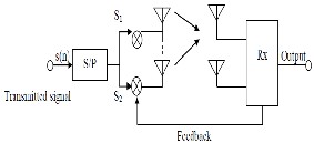
The general concept of spatial multiplexing can be under- stood using MIMO antenna configuration. In spatial multi- plexing, a high data rate signal is split into multiple lower data rate streams and each stream is transmitted from a different transmitting antenna in the same frequency channel. If these signals arrive at the receiver antenna array with different spa- tial signatures, the receiver can separate these streams into parallel channels thus improving the capacity. Thus spatial multiplexing is a very powerful technique for increasing channel capacity at higher SNR values. The maximum number of spatial streams is limited by the lesser number of antennas at the transmitter or receiver side. Spatial multiplexing can be used with or without transmit channel knowledge.
MIMO spatial multiplexing achieves this by utilizing the multiple paths and effectively using them as additional chan- nels to carry data such that receiver receives multiple data at the same time. The tenet in spatial multiplexing is to transmit different symbols from each antenna and the receiver dis- criminates these symbols by taking advantage of the fact that, due to spatial selectivity, each transmit antenna has a different spatial signature at the receiver . This allows an increased number of information symbols per MIMO symbol. In any case for MIMO spatial multiplexing, the number of receiving antennas must be equal to or greater than the number of transmit antennas such that data can be transmitted over dif- ferent antennas. Therefore the space dimension is reused or multiplexed more than one time. The data streams can be separated by equalizers if the fading processes of the spatial channels are nearly independent. Spatial multiplexing re- quires no bandwidth expansion and provides additional data bandwidth in multipath radio scenarios [2].
IJSER © 2013
International Journal of Scientific & Engineering Research Volume 4, Issue ŗŗǰȱ ȬŘŖŗřȱ
ISSN 2229-5518
220
i Phase Shift Keying (PSK)
Phase Shift Keying is a digital modulation scheme that con- veys data by changing or modulating, the phase of a reference signal (the carrier wave). In M-ary PSK modulation, the ampli- tude of the transmitted signals was constrained to remain con- stant, thereby yielding a circular constellation. Modulation equation of M-PSK signal is:![]()
Fig.1 Spatial Multiplexing Concept
![]()
![]()
cos i 0, 1,…., M (2)
Multiple- input multiple-output (MIMO) systems are a natural extension of developments in antenna array communi- cation. MIMO systems may be implemented in a number of different ways to obtain either a diversity gain to combat sig- nal fading or to obtain a capacity gain A MIMO system takes advantage of the spatial diversity that is obtained by spatially separated antennas in a dense multipath scattering environ- ment. Generally, there are three categories of MIMO tech- niques. The first aims to improve the power efficiency by max- imizing spatial diversity. Such techniques include delay diver- sity, STBC and STTC. The second class uses a layered ap- proach to increase capacity. One popular example of such a system is V-BLAST suggested by Foschini et al. [2] where full spatial diversity is usually not achieved. Finally, the third type exploits the knowledge of channel at the transmitter. It de- composes the channel coefficient matrix using SVD and uses these decomposed unitary matrices as pre- and post-filters at the transmitter and the receiver to achieve near capacity [3].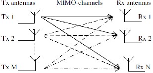
Fig. 2 Block Diagram of a generic MIMO system with M transmitters and N receivers
Modulation is the process of mapping the digital informa- tion to analog form so it can be transmitted over the channel. Consequently every digital communication system has a modulator that performs this task. Closely related to modula- tion is the inverse process, called demodulation, done by the receiver to recover the transmitted digital information [4]. Modulation of a signal changes binary bits into an analog waveform. Modulation can be done by changing the ampli- tude, phase, and frequency of a sinusoidal carrier. There are several digital modulation techniques used for data transmis- sion.
Channel is a transmission medium between the transmitter and receiver side. Channel can be air or space but it induces fading as well as distortions in the transmitted signal in such a way that the received signal is not same as that of transmitted signal but is a combination of reflected, diffracted and scat- tered copies of the transmitted signal. These copies are called multipath signal components. AWGN and Rayleigh fading channels have been taken into consideration for the analysis purpose.
Additive white Gaussian noise (AWGN) channel is univer- sal channel model for analyzing modulation schemes. In this model, the channel does nothing but add a white Gaussian noise to the signal passing through it. This implies that the channel’s amplitude frequency response is flat (thus with unlimited or infinite bandwidth) and phase frequency re- sponse is linear for all frequencies so that modulated signals pass through it without any amplitude loss and phase distor- tion of frequency components. Fading does not exist. The only distortion is introduced by the AWGN. AWGN channel is a theoretical channel used for analysis purpose only. The re- ceived signal is simplified to:
r(t)=s(t)+n(t) (3)
where n(t) is the additive white Gaussian noise.
Constructive and destructive nature of multipath compo- nents in flat fading channels can be approximated by Rayleigh distribution if there is no line of sight which means when there is no direct path between transmitter and receiver. The re- ceived signal can be simplified to:
r(t)=s(t)*h(t)+n(t) (4)
where h(t) is the random channel matrix having Rayleigh dis-
tribution and n(t) is the additive white Gaussian noise. The
Rayleigh distribution is basically the magnitude of the sum of
two equal independent orthogonal Gaussian random variables and the probability density function (pdf) given by :![]()
![]()
0≤ ≤ (5)
IJSER © 2013
International Journal of Scientific & Engineering Research Volume 4, Issue ŗŗǰȱ ȬŘŖŗřȱ
ISSN 2229-5518
221
where σ2 is the time-average power of the received signal.
There are numerous detection techniques available with combination of linear and non-linear detectors. The most common detection techniques are ZF, MMSE and ML detec- tion technique.
i Zero Forcing (ZF) Detection
The ZF is a linear estimation technique, which inverse the frequency response of received signal, the inverse is taken for the restoration of signal after the channel. The estimation of strongest transmitted signal is obtained by nulling out the weaker transmit signal. The strongest signal has been sub- tracted from received signal and proceeds to decode strong signal from the remaining transmitted signal. ZF equalizer
(11)
The system discussed above has been designed and results are shown in the form of SNR vs. BER plot for different modu- lations and different channels. Here antenna configuration 3x3 is analysed using ZF and MMSE detection techniques. Analy- ses have been done for two channels AWGN and Rayleigh channel.
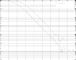
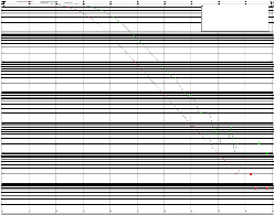
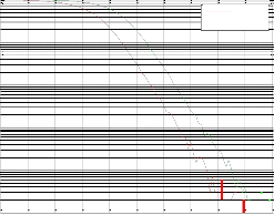
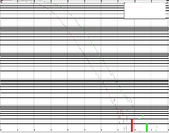
32-PSK modulation with 3x3 MIMO for AWGN and Rayleigh channel with ZF
0
10
AWGN
ignores the additive noise and may significantly amplify noise -1
for channel.
-2
10
The basic Zero force equalizer of 2x2 MIMO channel can be
-3
modeled by taking received signal during first slot at re- 10
ceiver antenna as: -4
10
, , = , , + n1 (6) -5
-6
10
The received signal y2 at the second slot receiver antenna is:
Rayleigh
y2 , , , , (7) Where i=1, 2 in xi is the transmitted symbol and i=1, 2 in hi, j is correlated matrix of fading channel, with j represented trans- mitted antenna and i represented receiver antenna ,n is the noise.
The ZF equalizer is given by:
(8)
Where WZF is equalization matrix and H is a channel matrix.
Assuming MR and H has full rank, the result of ZF
equalization before quantization is written as:
HH y (9)
ii Minimum Mean Square Estimator
Minimum mean square error equalizer minimizes the mean- square error between the output of the equalizer and the transmitted symbol, Instead of removing ISI completely; an MMSE equalizer allows some residual ISI to minimize the overall distortion. Compared with a ZF equalizer, an MMSE equalizer is much more robust in presence of deepest channel nulls and noise. The MMSE equalization is:
, (10)
Where is WMMSE equalization matrix, H channel correlated
matrix and n is channel noise.
-7
10
0 10 20 30 40 50 60 70 80 90
Average Eb/No,dB
Fig. 4(a)
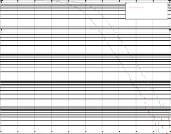
64-PSK modulation with 3x3 MIMO for AWGN and Rayleigh channel with ZF
0
10
AWGN
-1 Rayleigh
10
-2
10
-3
10
-4
10
-5
10
-6
10
-7
10
0 10 20 30 40 50 60 70 80 90 100
Average Eb/No,dB
Fig. 4(b)
IJSER © 2013
International Journal of Scientific & Engineering Research Volume 4, Issue ŗŗǰȱ ȬŘŖŗřȱ
ISSN 2229-5518
222
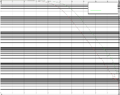
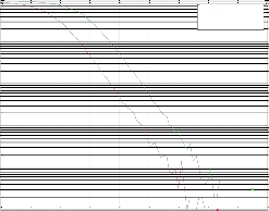
128-PSK modulation with 3x3 MIMO for AWGN and Rayleigh channel with ZF
0
10
AWGN
1024-PSK modulation with 3x3 MIMO for AWGN and Rayleigh channel with ZF
0
10
AWGN
-1 Rayleigh
10 -1
10
Rayleigh
-2
10
-2
10
-3
10
-3
10
-4
10
-4
10
-5
10
-5
-6 10
10
-7
10
0 10 20 30 40 50 60 70 80 90 100
Average Eb/No,dB
Fig. 4(c)
256-PSK modulation with 3x3 MIMO for AWGN and Rayleigh channel with ZF
0
10
AWGN
-1 Rayleigh
10
-6
10
0 10 20 30 40 50 60 70 80 90 100
Average Eb/No,dB
Fig. 4(f)
Fig. 4 BER vs. SNR plots over AWGN & Rayleigh channel for SM tech- nique using 3x3 MIMO System using ZF Equalization
a) 32 PSK b) 64 PSK c) 128 PSK d) 256 PSK e) 512 PSK
f) 1024 PSK
-2
10
-3 Table 1
Comparison of different Modulation Techniques for Rayleigh &
-4 AWGN Channel for 3x3 MIMO Spatial Multiplexing using ZF Equalization
-5
10
-6
10
-7
10
0 10 20 30 40 50 60 70 80 90 100
Average Eb/No,dB
Fig. 4(d)
512-PSK modulation with 3x3 MIMO for AWGN and Rayleigh channel with ZF
0
10
AWGN Rayleigh
-1
10
-2
10
-3
10
-4
10
From Table 1 we can say that at 64-PSK, 128-PSK, 512-PSK there is an improvement of 8dB, at 1024-PSK there is an im- provement of 9dB and at 64-PSK improvement is 8Db at BER of
10-4. Table 1 shows the improvement in terms of decibels shown by proposed system employing SM technique for 3x3 MIMO system for different modulation schemes over different chan- nels.
-5
10
-6
10
0 10 20 30 40 50 60 70 80 90 100
Average Eb/No,dB
Fig. 4(e)
IJSER © 2013
International Journal of Scientific & Engineering Research Volume 4, Issue ŗŗǰȱ ȬŘŖŗřȱ
ISSN 2229-5518
223
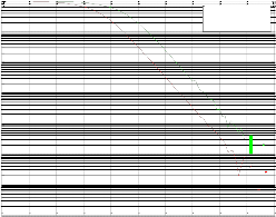
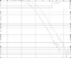
256-PSK modulation with 3x3 MIMO for AWGN and Rayleigh with MMSE
0
10
AWGN Rayleigh
32-PSK modulation with 3x3 MIMO for AWGN and Rayleigh with MMSE -1
0
10
AWGN Rayleigh
-2
-1 10
10
-3
-2 10
10
-4
10
-3
10
-4
10
-5
10
0 10 20 30 40 50 60 70 80 90
Average Eb/No,dB
Fig. 5(a)
-5
10
0 10 20 30 40 50 60 70 80 90 100
Average Eb/No,dB
Fig. 5(d)
512-PSK modulation with 3x3 MIMO for AWGN and Rayleigh with MMSE
0
10
AWGN Rayleigh
64-PSK modulation with 3x3 MIMO for AWGN and Rayleigh with MMSE -1
0
10
AWGN Rayleigh
-2
-1 10
10
-2
10
-3 -4
10 10
-4
10
-5
10
0 10 20 30 40 50 60 70 80 90
Average Eb/No,dB
Fig. 5(b)
128-PSK modulation with 3x3 MIMO for AWGN and Rayleigh with MMSE
0
10
AWGN Rayleigh
-1
10
-5
10
0 10 20 30 40 50 60 70 80 90 100
Average Eb/No,dB
Fig. 5(e)
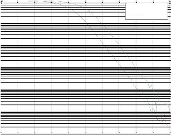
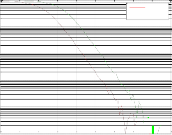
1024-PSK modulation with 3x3 MIMO for AWGN and Rayleigh with MMSE
0
10
AWGN Rayleigh
-1
10
-2
10
-3
-2
10
-4
-3
10
-4
10
-5
10
0 10 20 30 40 50 60 70 80 90 100
Average Eb/No,dB
Fig. 5(c)
-5
10
0 10 20 30 40 50 60 70 80 90 100
Average Eb/No,dB
Fig. 5(f)
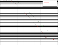
Fig. 5 BER vs. SNR plots over AWGN & Rayleigh channel for SM tech- nique using 3x3 MIMO System using MMSE Equalization
a)32 PSK b) 64 PSK c) 128 PSK d) 256 PSK e) 512 PSK
f) 1024 PSK
IJSER © 2013
International Journal of Scientific & Engineering Research Volume 4, Issue ŗŗǰȱ ȬŘŖŗřȱ
ISSN 2229-5518
224
Table 2
Comparison of different Modulation Techniques for Rayleigh & AWGN Channel for 3x3 MIMO Spatial Multiplexing using MMSE Equalization
Modulations | Rayleigh Channel | AWGN Channel | Improvement |
32-PSK | 67 dB | 61 dB | 6 dB |
64-PSK | 72 dB | 63 dB | 9 dB |
128-PSK | 79 dB | 68 dB | 11 dB |
256-PSK | 85 dB | 76 dB | 9 dB |
512-PSK | 91 dB | 83 dB | 8 dB |
1024-PSK | 94 dB | 85 dB | 9 dB |
Here table depicts that at 64-PSK, 256-PSK , 1024-PSK there is an improvement of 9dB, at 128-PSK there is an improvement of 11dB and at 512-PSK there is an improvement of 8dB at BER of 10-4. Hence table shows an improvement in terms of decibels shown by proposed system employing SM technique for 3x3
MIMO system for different modulation schemes over different channels.
In this paper, an idea about the performance of the MIMO- SM technique at higher modulation levels and for 3x3 antenna configuration using different signal detection technique is pre- sented. MIMO-SM technique can be implemented using higher order modulations to achieve large data capacity. But there is a problem of BER (bit error rate) which increases as the order of the modulation increases. The solution to this problem is to increase the value of the SNR so, that the effect of the distor- tions introduced by the channel will also goes on decreasing, as a result of this, the BER will also decreases at higher values of the SNR for high order modulations.
Several different diversity modes are used to make radio communications more robust, even with varying channels. These include time diversity (different timeslots and channel coding), frequency diversity (different channels, spread spec- trum, and OFDM), and also spatial diversity. Spatial diversity requires the use of multiple antennas at the transmitter or the receiver end. Multiple antenna systems are typically known as Multiple Input, Multiple Output systems (MIMO). Multiple antenna technology can also be used to increase the data rate (spatial multiplexing) instead of improving robustness. In fu- ture, we can make a single integrated circuit that uses both methods combination.
[1] H. Jiang and P. A. Wilford, "A hierarchical modulation for upgrading digital broadcasting systems," IEEE Transaction on Broadcasting, vol. 51, pp. 222-229, June 2005.
[2] P. W. Wolniansky, G. J. Foschini, G. D. Golden and R. A.Valenzuela, "V-BLAST: an architecture for realizing very high data rates over the rich-
scattering wireless channel," In Proceeding of International symposium on
Signals, Systems Electronics, pp. 259-300, October 1998.
[3] J. Ha, A. N. Mody, J. H. Sung, J. Barry, S. Mclaughlin and G. L. Stuber, “LDPC coded OFDM with Alamouti/SVD diversity technique,” IEEE Journal on Wireless Personal Communication, Vol. 23 , Issue 1,pp. 183-
194,Oct. 2002.
[4] P. S. Mundra , T. L. Singal and R. Kapur, “The Choice of A Digital Modulation ,Schemes in A Mobile Radio System”, In proceedings of IEEE Vehicular Technology Conference, Issue 5, pp 1-4,( Secaucus, NJ)1993.
[5] P. Liu & I1-Min Kim, “Exact and Closed-Form Error Performance Analysis for Hard MMSE-SIC Detection in MIMO Systems”, IEEE Trans- actions on Communication, Vol. 59, no. 9, September 2011.
[6] P. Sanghoi & L. Kansal,” Analysis of WiMAX Physical Layer Using Spatial Multiplexing Under Different Fading Channels”, SPIJ, Vol.(6),Issue(3),2012.
[7] C. Wang & E. K. S. Au, R. D Murch, W. H. Mow & V. Lau,” On the Performance of the MIMO Zero-Forcing Receiver in the Presence of Chan- nel Estimation Error”, IEEE Transactions on Wireless Communication, Vol. 6,no.3,2007.
[8] X. Zhang, Y. Su & G. Tao, “Signal Detection Technology Research of MIMO-OFDM System”, 3rd International Congress on Image and Signal Processing, pp 3031-3034, 2010.
[9] I. Ammu & R. Deepa, “Performance Analysis of Decoding Algorithms in multiple antenna systems”, IEEE, pp 258-262, 2011.
[10] H. B. Voelcker, “Phase-shift keying in fading channels” , In IEEE Pro- ceeding on Electronics and Communication Engineering, Vol. 107, Issue
31, pp 31-38, 1960.
[11] D. S. Shiu, G. J. Foschini, M. J. Gans, and J. M. Kahn, “Fading correla- tion and its effect on the capacity of multi-element antenna systems”, IEEE Transaction on Communication, Vol. 48, pp. 502–513, 2000.
[12] G. J. Foschini, K. Karakayali, and R. A.Valenzuela, “Coordinating multiple antenna cellular networks to achieve enormous spectral efficien- cy,” Communications, IEE Proceedings, Vol. 153, pp. 548–555, 2006.
[13] J. S. Thompson, B. Mulgrew and Peter M. Grant, “A comparison of the MMSE detector and its BLAST versions for MIMO channels”, IET seminar on Communication System from Concept to Implementation, pp.
1911-1916, 2001.
[14] X. Zhang and Sun-Yuan Kung, “Capacity analysis for parallel and sequential MIMO equalizers”, IEEE Transaction on Signal processing, Vol.
51, pp. 2989-3002, 2003.
IJSER © 2013