International Journal of Scientific & Engineering Research, Volume 6, Issue 3, March-2015
ISSN 2229-5518
356
Attributes affecting energy of Superconducting
Magnetic Energy Storage systems
Engy Elshazly, Nancy Emam, Prof. /Nabil Eltayeb
Abstract— Superconducting Magnetic Energy Storage (SMES) systems store energy in the magnetic field created by the flow of direct current in a superconducting coil which has been cryogenically cooled to a temperature below its superconducting critical temperature.
A typical SMES system includes three parts: superconducting coil, power conditioning system and cryogenically cooled refrigerator. Once the superconducting coil is charged, the current will not decay and the magnetic energy can be stored indefinitely.
The stored energy can be released back to the network by discharging the coil. The power conditioning system uses an inverter/rectifier to transform alternating current (AC) power to direct current or convert DC back to AC power. The inverter/rectifier accounts for about 2–3% energy loss in each direction. SMES loses the least amount of electricity in the energy storage process compared to other methods of storing energy. SMES systems are highly efficient; the round -trip efficiency is greater than 95%.[1]
Due to the energy requirements of refrigeration and the high cost of superconducting wire, SMES is currently used for short duration energy storage. Therefore, SMES is most commonly devoted to improving power quality.
Index Terms— Superconducting - Magnetic – Energy – Techniques – Contraction – Renewable – Coil.
1 Introduction
The use of renewable energy sources, such as solar, wind and hydraulic energies, is very old; they have been used since many centuries before our time and their applications continued throughout history and until the "industrial revolution", at which time, due to the low price of petroleum, they were abandoned.
During recent years, due to the increase in fossil fuel prices and the environmental problems caused by the use of conventional fuels, we are reverting back to renewable energy sources.
Renewable energies are inexhaustible, clean and they can be used in a decentralized way (they can be used in the same place as they are produced). Also, they have the additional advantage of being complimentary, the integration between them being favorable. For example, solar photovoltaic energy supplies electricity on sunny days (in general with low wind)
————————————————
Engy Elshazly masters degree program in Renewable Energy engineering in British University in Egypt, Cairo , Egypt, PH-01063068563. E-mail: engyelshazly@yahoo.com.
Nancy Emam masters degree program in Renewable Energy engineering in British University in Egypt, Cairo , Egypt, PH-01066582402. E-mail : nonna_powerdestroyer@yahoo.com.
Prof. /Nabil Eltayeb , Faculty of Engineering, Department of Mechanical
Engineering, Faculty of Engineering Building, British University in Egypt,
Cairo, Egypt., PH-01155685757. E-mail: Nabil.ElTayeb@Bue.edu.eg.
while on cold and windy days, which are frequently cloudy, the wind generators are in position to supply more electric energy [3].
Energy storage can reduce the time and rate mismatch between energy supply and energy demand. Finding new, efficient, and cheap ways to store energy is as vital as finding new sources of energy. Energy ca be generated and stored when the demand is low, and this stored energy can be used when there is a demand for it. There are different types of mismatch between the energy supply and the demand for it and this is the main reason for the importance of energy storage. Storing energy also helps reducing pollution and the cost of production.
Energy storage can reduce the time and rate mismatch between energy supply and energy demand. Finding new, efficient, and cheap ways to store energy is as vital as finding new sources of energy. Energy ca be generated and stored when the demand is low, and this stored energy can be used when there is a demand for it. There are different types of mismatch between the energy supply and the demand for it and this is the main reason for the importance of energy storage. Storing energy also helps reducing pollution and the cost of production. Also, stored energy is better suited for transportation to very long distances.
IJSER © 2015 http://www.ijser.org
International Journal of Scientific & Engineering Research, Volume 6, Issue 3, March-2015
ISSN 2229-5518
Electrical energy storage technologies are designed to absorb electrical energy (act like increased demand) directly and release it as electrical energy (act like a generator) at a later time.
There are numerous such technologies some well advanced 3in57
their development, others at the beginning.
Table1
Summary characteristics of various energy storage technologies[2].
14 Technology | Maturity | Cost ($/kW) | Cost ($/kWh) | Efficiency | Cycle Limited | Response Time |
Pumped Hydro | Mature | 1,500 - 2,700 | 138 - 338 | 80-82% | No | Seconds to Minutes |
Compressed Air (Underground) | Demo to Mature | 960 - 1,250 | 60 - 150 | 60-70% | No | Seconds to Minutes |
Compressed Air (Aboveground) | Demo to Deploy | 1,950 - 2,150 | 390 - 430 | 60-70% | No | Seconds to Minutes |
Flywheels | Deploy to Mature | 1,950 - 2,200 | 7,800 - 8,800 | 85-87% | >100,000 | Instantaneous |
Lead Acid Batteries | Demo to Mature | 950 - 5,800 | 350 - 3,800 | 75-90% | 2,200 - >100,000 | Milliseconds |
Lithium-ion Batteries | Demo to Mature | 1,085 - 4,100 | 900 - 6,200 | 87-94% | 4,500 - >100,000 | Milliseconds |
Flow Batteries (Vanadium Redox) | Develop to Demo | 3,000 - 3,700 | 620 - 830 | 65-75% | >10,000 | Milliseconds |
Flow Batteries (Zinc Bromide) | Demo to Deploy | 1,450 - 2,420 | 290 - 1,350 | 60-65% | >10,000 | Milliseconds |
Sodium Sulfur | Demo to Deploy | 3,100 - 4,000 | 445 - 555 | 75% | 4,500 | Milliseconds |
Power To Gas | Demo | 1,370 - 2,740 | NA | 30-45% | No | 10 Minutes |
Capacitors | Develop to Demo | - | - | 90-94%13 | No | Milliseconds |
SMES | Develop to Demo | - | - | 95%14 | No | Instantaneous |
Capacitors consist of two electrical conductors separated by a non-conducting material (the dielectric). When a charge is applied across the plates electrical charge builds up on either side. Energy is stored in the electrical field between the two plates.
Electrochemical capacitors (also called double layer, super- capacitors or ultra-capacitors) have a higher energy density than other capacitors. Some double layer capacitors have a voltage rating at or above 600V. This makes them suitable for power quality and intermittent renewables fluctuation suppression applications.
Their disadvantages include interdependence of the cells, sensitivity to cell voltage imbalances and maximum voltage thresholds, and safety issues, including electrical, fire, chemical, and explosion hazards. In this paper we will take about the Superconducting Magnetic Energy Storage (SMES) which uses the flow of direct current through a cryogenically cooled superconducting coil to generate a magnetic field that stores energy. Once the superconducting coil is charged, the current will not deteriorate and the magnetic energy can be stored indefinitely. The stored energy is released by discharging the coil. Cryogenic
IJSER © 2015
refrigeration is required to keep the device cold enough to maintain superconducting properties.
SMES units offer “permanent” storage, immediate response, life expectancy independent of duty cycle, and high efficiency and reliability. In this case permanent means that the energy is held indefinitely, with no standby losses due to heat dissipation, evaporation, etc. This, coupled with the nearly instantaneous response speeds SMES are capable of, make SMES an excellent choice for uninterrupted power supplies (UPS) and power quality applications. Additionally SMES units boast round trip efficiency above 95% with few mechanical parts, limiting failure points and increasing reliability.
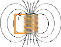
Fig. 1 : The Superconducing coil
http://www.ijser.org
International Journal of Scientific & Engineering Research, Volume 6, Issue 3, March-2015
ISSN 2229-5518
358
SMES is a grid-enabling device that stores and discharges large quantities of power almost instantaneously. The system is capable of releasing high levels of power within a fraction of a cycle to replace a sudden loss or dip in line power. Strategic injection of brief bursts of power can play a crucial role in maintaining grid reliability especially with today’s increasingly congested power lines and the high penetration of renewable energy sources, such as wind and solar.
A typical SMES consists of two parts – cryogenically cooled superconducting coil and power conditioning system – which are motionless and result in higher reliability than many other power storage devices. Ideally, once the superconducting coil is charged, the current will not decay and the magnetic energy can be stored indefinitely.
2 Calculation of stored energy
The magnetic energy stored by a coil carrying a current is given by one half of the inductance of the coil times the square of the current.
3 Solenoid versus toroid
Besides the properties of the wire, the configuration of the coil itself is an important issue from a mechanical engineering aspect. There are three factors which affect the design and the shape of the coil - they are: Inferior strain tolerance, thermal contraction upon cooling and Lorentz forces in a charged coil. Among them, the strain tolerance is crucial not because of any electrical effect, but because it determines how much structural material is needed to keep the SMES from breaking. For small SMES systems, the optimistic value of 0.3% strain tolerance is selected. Toroidal geometry can help to lessen the external magnetic forces and therefore reduces the size of mechanical support needed. Also, due to the low external magnetic field, toroidal SMES can be located near a utility or customer load.
For small SMES, solenoids are usually used because they are easy to coil and no pre-compression is needed. In toroidal SMES, the coil is always under compression by the outer hoops and two disks, one of which is on the top and the other is on the bottom to avoid breakage. Currently, there is little need for toroidal geometry for small SMES, but as the size increases, mechanical forces become more important and the toroidal coil is needed.
Where
E = ½ L I 2
E = energy measured in joules
L = inductance measured in henries
I = current measured in amperes
The older large SMES concepts usually featured a low aspect ratio solenoid approximately 100 m in diameter buried in earth. At the low extreme of size is the concept of micro-SMES solenoids, for energy storage range near 1 MJ.
4 Low-temperature versus high-temperature superconductors
Under steady state conditions and in the superconducting
Now let’s consider a cylindrical coil with conductors of a rectangular cross section. The mean radius of coil is R. a and b are width and depth of the conductor. f is called form function which is different for different shapes of coil. ξ (xi) and δ (delta) are two parameters to characterize the dimensions of the coil. We can therefore write the magnetic energy stored in such a cylindrical coil as shown below. This energy is a function of coil dimensions, number of turns and carrying current.
E = ½ R N 2 I 2 f
Where
E = energy measured in joules
I = current measured in amperes
f(ξ,δ) = form function, joules per ampere-meter
N = number of turns of coil
state, the coil resistance is negligible. However, the refrigerator necessary to keep the superconductor cool requires electric power and this refrigeration energy must be considered when evaluating the efficiency of SMES as an energy storage device.
Although the high-temperature superconductor (HTSC) has higher critical temperature, flux lattice melting takes place in moderate magnetic fields around a temperature lower than this critical temperature. The heat loads that must be removed by the cooling system include conduction through the support system, radiation from warmer to colder surfaces, AC losses in the conductor (during charge and discharge), and losses from the cold–to-warm power leads that connect the cold coil to the power conditioning system. Conduction and radiation losses are minimized by proper design of thermal surfaces. Lead losses can be minimized by good design of the leads. AC losses depend on the design of the conductor, the duty cycle of the device and the power rating [5].
The refrigeration requirements for HTSC and low-
IJSER © 2015 temperature superconductor (LTSC) toroidal coils for the
http://www.ijser.org
International Journal of Scientific & Engineering Research, Volume 6, Issue 3, March-2015
ISSN 2229-5518
359
baseline temperatures of 77 K, 20 K, and 4.2 K, increases in that order. The refrigeration requirements here is defined as electrical power to operate the refrigeration system. As the stored energy increases by a factor of 100, refrigeration cost only goes up by a factor of 20. Also, the savings in refrigeration for an HTSC system is larger (by 60% to 70%) than for an LTSC systems.
5 The Coil and the Superconductor
The superconducting coil, the heart of the SMES system, stores energy in the magnetic field generated by a circulating current (EPRI, 2002). The maximum stored energy is determined by two factors: a) the size and geometry of the coil, which determines the inductance of the coil. The larger the coil, the greater the stored energy; and b) the characteristics of the conductor, which determines the maximum current. Superconductors carry substantial currents in high magnetic fields.
All practical SMES systems installed to date use a superconducting alloy of niobium and titanium (Nb-Ti), which requires operation at temperatures near the boiling point of liquid helium, about 4.2 K (-269°C or -452°F) – 4.2 centigrade degrees above absolute zero. Some research- based SMES coils use high-temperature superconductors (HTS).However, the state of development of these materials today is such that they are not cost effective for SMES.
Since only a few SMES coils have been constructed and installed, there is little experience with a generic design. This is true even for the small or micro-SMES units for power-quality applications, where several different coil designs have been used. A primary consideration in the design of a SMES coil is the maximum allowable current in the conductor. It depends on: conductor size, the superconducting materials used, the resulting magnetic field, and the operating temperature. The magnetic forces can be significant in large coils and must be reacted by a structural material. The mechanical strength of the containment structure within or around the coil must withstand these forces. Another factor in coil design is the withstand voltage, which can range from 10 kV to 100 kV [4] .
6 Cryogenic Refrigerator
The superconducting SMES coil must be maintained at a temperature sufficiently low to maintain a superconducting state in the wires. As mentioned, for commercial SMES today this temperature is about 4.5 K (-269°C, or -452°F).
Reaching and maintaining this temperature is accomplished by a special cryogenic refrigerator that uses helium as the coolant. Helium must be used as the so called "working fluid" in such a refrigerator because it is the only material that is not a solid at these temperatures. Just as a conventional refrigerator requires power to operate, electricity is used to power the cryogenic refrigerator
(EPRI, 2002). As a result, there is a tremendous effort in the
design of SMES and other cryogenic systems to lower losses within the superconducting coils and to minimize heat flow into the cold environment from all sources.
The refrigerator consists of one or more compressors for gaseous helium and a vacuum enclosure called a “cold- box”, which receives the compressed, ambient-temperature helium gas and produces liquid helium for cooling the coil
.
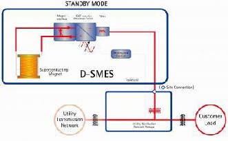
Fig. 2: d-smes_one_line
7 Power Conversion System
Charging and discharging a SMES coil is different from that of other storage technologies. The coil carries a current at any state of charge. Since the current always flows in one direction, the power conversion system (PCS) must produce a positive voltage across the coil when energy is to be stored, which causes the current to increase. Similarly, for discharge, the electronics in the PCS are adjusted to make it appear as a load across the coil. This produces a negative voltage causing the coil to discharge. The product of this applied voltage and the instantaneous current determine the power.
SMES manufacturers design their systems so that both the coil current and the allowable voltage include safety and performance margins. Thus, the PCS power capacity typically determines the rated capacity of the SMES unit (EPRI, 2002). The PCS provides an interface between the stored energy (related to the direct current in the coil) and the AC in the power grid.
8 Control System
The control system establishes a link between power demands from the grid and power flow to and from the SMES coil. It receives dispatch signals from the power grid and status information from the SMES coil. The integration of the dispatch request and charge level determines the response of the SMES unit. The control system also measures the condition of the SMES coil, the refrigerator, and other equipment. It maintains system safety and sends system status information to the operator. Modern SMES systems are tied to the Internet to provide remote
IJSER © 2015 observation and control [7].
http://www.ijser.org
International Journal of Scientific & Engineering Research, Volume 6, Issue 3, March-2015
ISSN 2229-5518
360
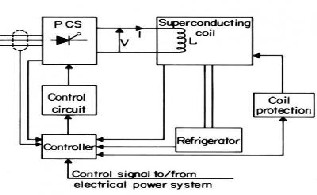
Fig. 3 : schematic_of_smes_system
9 Technical attributes of SMES
The following four technical attributes of SMES are discussed in this section: a) capacity of a SMES system; b) the energy storage rating; c) the physical dimensions; and d) the efficiency of a SMES system [6] .
9.1 Capacity
The power capacity for a SMES system is dictated by the application, e.g., power quality, power system stability, or load leveling. In general, the maximum power capacity is the smaller of two quantities: either the PCS power rating or the product of the peak coil current and the maximum coil withstand voltage. The capacities of existing individual micro-SMES installations range from 1 MW to about 3 MW.
9.2 The energy storage rating
The stored energy in the SMES plant depends on the requirements of the application. It is the product of the power capacity and the length of time the installation is to deliver this power [8].
9.3 Physical dimensions
The physical size of a SMES system is the combined sizes of the coil, the refrigerator and the PCS. Each of these depends on a variety of factors. The coil mounted in a cryostat is often one of the smaller elements. A 3 MJ micro- SMES system (coil, PCS, refrigerator and all auxiliary equipment) is completely contained in a 40-ft trailer.
9.4 Efficiency of the system
The overall efficiency of a SMES plant depends on many factors. In principle, it can be as high as 95 % in very large systems. For small power quality systems, on the other hand, the overall system efficiency is less. Fortunately, in these applications, efficiency is usually not a significant economic driver. The SMES coil stores energy with absolutely no loss while the current is constant. There are, however, some losses associated with changing current
during charging and discharging, and the resulting chaIJnSgEeR © 2015
in magnetic field. In general, these losses, which are referred to as eddy current and hysteresis losses, are also small.
Unfortunately, other parts of the SMES system may not be as efficient as the coil itself. In particular, there are two potentially significant, continuous energy losses, which are application specific:
1) The first is associated with the way SMES systems store the energy. The current in the coil must flow continuously, and it circulates through the PCS. Both the interconnecting conductors and the silicon-based components of the PCS are resistive. Thus, there are continuous resistive losses in the PCS. This is different from batteries, for example, where there is current in the PCS only during charge and discharge.
2) The energy that is needed to operate the refrigerator that removes the heat that flows to the coil from room temperature via: a) conduction along the mechanical supports, b) radiation through the vacuum containment vessel, and c) along the current leads that extend from ambient temperature to the coil operating temperature.
The overall efficiency of a SMES plant depends on many factors. Diurnal (load-leveling) SMES plants designed 20 years ago were estimated to have efficiencies of 90 to 92%. Power quality and system stability applications do not require high efficiency because the cost of maintenance power is much less than the potential losses to the user due to a power outage. Developers rarely quote efficiencies for such systems, although refrigeration requirements are usually specified
Results and discussion
The energy content of current SMES systems is usually quite small. Methods to increase the energy stored in SMES often resort to large-scale storage units. As with other superconducting applications, cryogenics are a necessity. A robust mechanical structure is usually
required to contain the very large Lorentz forces generated by and on the magnet coils. The dominant cost for SMES
is the superconductor, followed by the cooling system and
the rest of the mechanical structure.
Mechanical support - Needed because of Lorentz forces.
Size - To achieve commercially useful levels of storage, around 1 GW·h (3.6 TJ), a SMES installation would need a loop of around 100 miles (160 km). This is traditionally pictured as a circle, though in practice it could be more like a
rounded rectangle. In either case it would require
access to a significant amount of land to house the installation.
Manufacturing - There are two manufacturing issues around SMES. The first is the fabrication of bulk cable suitable to carry the current. Most of the superconducting materials found to date
http://www.ijser.org
International Journal of Scientific & Engineering Research, Volume 6, Issue 3, March-2015
ISSN 2229-5518
361
are relatively delicate ceramics, making it difficult to use established techniques to draw extended lengths of superconducting wire. Much research has focussed on layer deposit
techniques, applying a thin film of material onto a stable substrate, but this is currently only suitable for small-scale electrical circuits.
Infrastructure - The second problem is the infrastructure required for an installation. Until room-temperature superconductors are found, the
100 mile (160 km) loop of wire would have to be contained within a vacuum flask of liquid nitrogen. This in turn would require stable support, most commonly envisioned by burying the installation.
Critical magnetic field - Above a certain field strength, known as the critical field, the superconducting state is destroyed.
Critical current - In general power systems look to maximize the current they are able to handle. This makes any losses due to inefficiencies in the system relatively insignificant. Unfortunately, large currents may generate magnetic fields greater than the critical field due to Ampere's Law. Current materials struggle, therefore, to carry sufficient current to make a commercial storage facility economically viable.
Several issues at the onset of the technology have hindered its proliferation:
1. Expensive refrigeration units and high power cost to maintain operating temperatures
2. Existence and continued development of adequate technologies using normal conductors
These still pose problems for superconducting applications but are improving over time. Advances have been made in the performance of superconducting materials. Furthermore, the reliability and efficiency of refrigeration systems has improved significantly to the point that some devices are now able to operate on electrical power
systems
Conclusions
Due to the energy requirements of refrigeration and the high cost of superconducting wire, SMES is currently used for short duration energy storage. Therefore, SMES is most commonly devoted to improving power quality.
Acknowledgment
We are thankful to the British University in Egypt, Cairo, Egypt support.
References
[1] ^Cheung K.Y.C, Cheung S.T.H, Navin De Silvia R.G, Juvonen M.P.T, Singh R, Woo J.J. Large-Scale Energy Storage Systems. Imperial College London: ISE2, 2002/2003.
[2] ecofys-2014-energy-storage-white-paper.
[3] Hassenzahl, W.V.,"Applied Superconductivity, Superconductivity, an enabling technology for 21st century power systems?", IEEE Transactions on Magnetics, pp. 1447-1453, Volume: 11, Issue: 1, Mar
2001.
[3] Overview of current and future energy storage technologies for electric power applications.
[4] ^Tixador, P. Superconducting Magnetic Energy
Storage: Status and Perspective.
[5] Sheahen, T., P. (1994). Introduction to High- Temperature Superconductivity. Plenum Press, New York.
[6] ^http://www.solener.com.
[7] ^http://www.climatetechwiki.org.
[8] ^http://www.innovation-america.org /superconductors- and-energy-storage.
IJSER © 2015 http://www.ijser.org