International Journal of Scientific & Engineering Research, Volume 2, Issue 12, December-2011 1
ISSN 2229-5518
Application of Capacitive Energy Storage Unit for
Automatic Generation Control of
Two Area Two Unit Power System
V.V.Vijetha Inti, K.Ratna Raju, Aswani Kumar Eedara
Abstract: This paper is about the application of Capacitive Energy Storage unit (CES) to two area two unit powersystem to improve dynam ic performance of automatic generation control. Simulation is done without CES, with CES unit by taking frequency error as control input and with CES unit by taking Area Control Error (ACE) as Control input. Simulation studies show that CES units are capable of reducing the settling time of the responses. Simulation study also reveals that the dynamic responses with frequency deviations as feedback to CES are better than that obtained with ACE as feedback to CES unit and far superior than that without CES units.
Index Terms: Automatic generation control, capacitive energy storage, Area control error, generation rate Constraint, Area participation factor, Power
Conversion System, a super capacitor or a cryogenic hyper capacitor
—————————— ——————————
INTRODUCTION
lectric power consumption is highly dynamic, changes randomly at every instant. Hence electric power generation must match with consumption at every instant to maintain the system in its nominal state. Nominal state is characterized by nominal frequency, voltage profile, and load flow configuration. But 100% equilibrium can’t be met, in reality there is always generation-consumption mismatch. This mismatch causes a deviation of system frequency and tie line power from their scheduled values. To make the deviations to zero utilities prefer integral or proportional integral controllers in their system. How fast the deviations can be brought to zero is the point of
concern.
Some of the energy storage devices are designed to meet these needs are fly wheels, battery storage, compressed air, pumped hydro, fuel cells, superconducting magnetic energy storage (SMES), etc. Most of these technologies store electrical energy in other forms in addition to their own inherent disadvantages pointed out by [1]-[2]. Reference [3] has shown that the relative merits of Capacitive Energy Storage (CES) which outweigh Superconducting Magnetic Energy Storage (SMES).
V.V.Vijetha Inti is currently pursuing masters degree program in Power Electronics in NOVA college of Engineering and Technology at Jangareddygudem, India.
Email: vijethavas@gmail.com
K.Ratna Raju is currently working as Assistant professor in
Department of Electrical and Electronics Engineering in NOVA
college of Engineering and Technology at Jangaredygudem, India.
. E-mail: ratnaraju.11@gmail.com
Aswani Kumar Eedara is currently working as Assistant
Professor in Department of Electrical and Electronics in SASI Institute of Technology and Engineering at Tadepalligudem, India since 2008.
E-mail: aswani@sasi.ac.in
The main objectives of present work are modeling of
CES and its control logic, compare the dynamic responses
of frequency deviations, tie line power deviation, and change in generated power without and with CES units in two unit two area two unit power system.
Two Area Two Unit Power Systems:
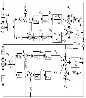
When the system is exposed to small change in load during its operation, a liberalized model is used to represent the system. Block diagram model of the two area power system is as shown in Fig.1. Area 1 consists of two reheat units and area 2 consists of two non-reheat units. A limit is present to the rate at which the output power of steam turbines can be changed because of the thermodynamic and mechanical constraints. This limit is known as Generation Rate Constraint (GRC). Now for this network, a GRC of 3% per min. for reheat units and 10% per min for non reheat units is considered for each unit in areas 1 and 2 respectively as in [4].The ACE participation factors in area 1 are apf11 and apf12 and the ACE participation factors in area 2 are apf21 and apf22. Note that apf11 + apf12 = 1.0 and apf21 + apf22 = 1.0. A small rating CES unit of 3.8 MJ storage capacity is fitted to both the areas 1 and 2 to examine its effect on the power system performance. A step load disturbance of 0.01 per unit is considered in area 1 for investigation. The control signal to the CES unit can be frequency deviation or the Area Control Error (ACE). In this paper, both the cases are studied.
IJSER © 2011 http://www.ijser.org
International Journal of Scientific & Engineering Research, Volume 2, Issue 12, December-2011 2
ISSN 2229-5518
current to bypass and the dc breaker allows current to be diverted into the energy dump resistor if the converter fails. Assuming the losses to be negligible, the bridge voltage Ed is given [5]
(1)
Fig.1 Model of two Area two unit interconnected Power
System with CES units
Modeling of Capacitive Energy Storage Unit:
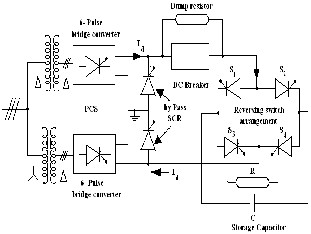
A Capacitive Energy Storage (CES) consists of a super capacitor or a cryogenic hyper capacitor (CHC), a Power Conversion System (PCS) and the associated circuitry. Capacitive energy storage unit is as shown in Fig. 2.CHC has a peak dielectric constant of 77K.
Fig. 2 Capacitive Energy Storage Unit
The resistor R is connected in parallel across the capacitor represents dielectric and leakage losses of the capacitor bank. The PCS forms an electrical interface between the capacitor and the power system, consists of ac to dc rectifier and a dc-to-ac inverter. The thyristors provide a path for
The voltage across the capacitor Ed can be varied
from its maximum value to minimum value by changing the phase angle .The firing pulses are given in appropriate timings and hence the voltage and power is defined by the value .Thus, without any switching operation, reversibility and magnitude control of the power flow is achieved by continuously controlling the firing angle α and it is controlled by an algorithm. A firing angle is calculated and transmitted to the firing circuit based on the voltage across the capacitor. As the response time of the control and firing circuits is very short, a new firing angle is chosen within a few milliseconds for the very next SCR to be pulsed. This rapid response to power demand is the major capability of CES relative to other energy storage systems. The change of direction of the current in the capacitor during charging (rated load period) and discharging (during peak load period), can be provided by the reversing switch arrangement since the direction of the current through the bridge converter (rectifier/inverter) cannot change. During the charging mode, switches S1 and S4 are on and S2 and S3 are off. In the discharging mode, S2 and S3 are on and S1 and S4 are off. The operating point of capacitor is such that the total energy which is absorbed is equal to the total amount of energy discharged. If denotes the set value of voltage and and denote the maximum and minimum limits of voltage respectively, then,
and hence,


(2)
A low limit is imposed on capacitor voltage i.e., 30% of the rated value is used to overcome the voltage fluctuations which occur due to a sudden disturbance. Initially capacitor is charged to its set value .At this position value will be and now CES is ready to operate. When load is raised suddenly, the stored energy is released immediately through the PCS to the grid as pulsed AC. As the governor and other control mechanisms start working to set the power system to the new equilibrium condition, the capacitor charges to its initial value of voltage Ed0.Similar action takes place if load is reduced. The capacitor immediately gets charged towards its full value, thus absorbing some portion of the excess energy in the system,
IJSER © 2011 http://www.ijser.org
International Journal of Scientific & Engineering Research, Volume 2, Issue 12, December-2011 3
ISSN 2229-5518
and as the system returns to its steady state, the absorbed
energy is released and the capacitor voltage attains its normal value.
The power flow into the capacitor at any instant is
= . and the initial power flow into the capacitor is =
. Where and are prior to the load disturbance. When a load disturbance occurs, the power flow into the coil is
+ = ( + )( + )
The term Ed0.Id0 is neglected since Ed0 = 0 in the storage mode to hold the rated voltage at constant value. So that the incremental power change in the capacitor is
= ( ) (3)
Block Diagram of CES:
After any load disturbance the set value of CES voltage has to be restored so that the CES is ready to act for other load disturbance. For this, the capacitor voltage deviation can be sensed and used as a negative feedback signal in the CES control loop so that fast restoration of the voltage is achieved as shown in Fig.3
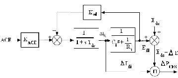
Fig.3 CES block diagram with capacitor voltage deviation feedback
CES Control Logic:
is continuously controlled in accordance with the control signal. The control signal of CES unit can be provided either by Area Control Error (ACE) or frequency deviation. For the area, if the frequency deviation (i.e., Δerrori = ). of the power system is used as the control signal to CES, then the deviation in the current, is given by

(4)
control signal (i.e., Δerrori = ACEi).As a function of tie-line
power deviations, ACE as the control signal to CES, may further improve the tie-power oscillations. Thus, ACE of the two areas is given by
(5)
Where is the change in tie-line power flow out of area I to j. Thus, if ACE is the control signal to the CES, then the deviation in the current would be

; i,j=1,2. (6)
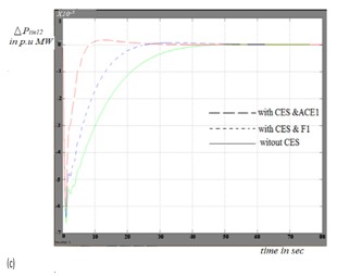
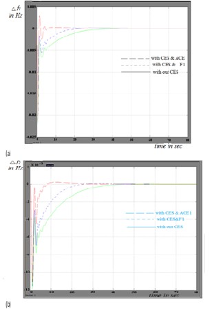
Simulation Results:
To obtain the dynamic responseof the two area system 0.01p.u. step input is given as load disturbance in area 1. The area participation factors are taken as apf11 = apf12 = 0.5 and apf21 = apf22 = 0.5.The system is simulated for a time of 80sec without CES unit, with CES units having Δf1or ACE1 as the control logic signals. From results as shown in figure 4, it is evident that the dynamic responses have improved significantly with the use of CES units. It is observed that with the use of Δf1 feedback to the CES control block, the dynamic responses are better than those obtained with ACE1.As the load disturbance has occurred in area 1, at steady state, the power generated by generating units in area 1 are in proportion to the ACE participation factors. Therefore, as in Fig. 4(d),(e),(f)and(g) at steady state, ΔPg1ss = ΔPd1 × apf11 = 0.01 × 0.5 =0.005 p.u. MW and ΔPg2ss = ΔPd2 × apf12 = 0.01 × 0.5=0.005p.u. MW. Similarly, ΔPg3ss = ΔPd2 × apf21 = 0 × 0.5 = 0 p.u.MW and ΔPg4ss = ΔPd2 × apf21 = 0 × 0.5 = 0 p.u. MW at steady state.
Conclusions:
In this paper, the responses of a two-area interconnected thermal power system with reheat and non reheat units have been studied. Responses show that Capacitive Energy Storage units are capable of consuming the oscillations in area frequency deviations and tie-line power deviations of the power system. Further, CES units reduce the settling time of the responses. Two different control logic signals for CES units are employed and it was found that, the dynamic responses with frequency feedback to CES are better than that obtained with ACE feedback to CES units and far superior than that without CES units. Hence, it may be concluded that CES units are efficient and effective for improving the dynamic performance of AGC of interconnected power systems.
If the tie-line power flow deviations can be sensed, then
the Area Control Error (ACE) can be fed to the CES as the
IJSER © 2011 http://www.ijser.org
International Journal of Scientific & Engineering Research, Volume 2, Issue 12, December-2011 4
ISSN 2229-5518
References:
*1+ Al Pivec, B.M. Radimer and E.A. Hyman,“ Utility Operation of Battery Energy Storage at the BEST facility,” IEEE Transactions on Energy Conversion, vol. EC-1, 1986, pp. 47-54
[2] J.D. Boyes and N.H. Clark,” Technologies for Energy Storage Flywheels and Superconducting Magnetic Energy Storage,” in Proc. Power Engineering Society Summer Meeting, 2000, pp. 1548-1550
*3+ E. Schempp and W.D. Jackson,”Systems
Considerations in Capacitive Energy Storage,” Proc. IEEE
Conf. on Energy Conversion Engg, 1996
*4+ R.J.Abraham, ”Automatic Generation Control in Traditional and Deregulated Environments,” Ph.D dissertation, Dept. Elect. Eng., Indian Institute of Technology, Kharagpur, 2007
[5] R.J.Abraham, D. Das and A. Patra,”Effect of Capacitive
Energy Storage on Automatic Generation Control,” Proc.
7th International Power Engineering Conference, Singapore, 2005, pp. 1070-1074.
IJSER © 2011 http://www.ijser.org
International Journal of Scientific & Engineering Research, Volume 2, Issue 12, December-2011 5
ISSN 2229-5518
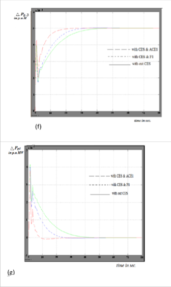
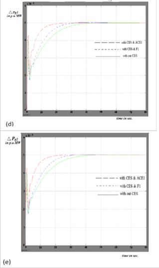
Fig. 4 Dynamic responses considering a step load disturbance of 0.01 pu in area-1.
(a)∆f1(b) ∆f2(c) ∆Ptie12 (d)∆Pg1(e)∆Pg2(f) ∆Pg3 and
(g) ∆ Pg4
IJSER © 2011 http://www.ijser.org