International Journal of Scientific & Engineering Research Volume 2, Issue 2, February-2012 1
ISSN 2229-5518
Analysis of the Dynamic Characteristics of an Isolated Self-Excited Induction Generator Driven by a Wind-Turbine
Godswill Ofualagba
Abstract-This paper focuses on the electrical generation part of a wind energy conversion system. After a brief introduction of the induction machine, the electrical generator used in this paper, a detailed analysis of the induction machine operated in stand-alone mode is presented. As a generator, induction machines have the drawback of requiring reactive power for excitation. This necessitates t he use of shunt capacitors in the circuit. The effect of magnetization inductance on self-excitation of the induction generator is discussed. Also, this paper presents the two existing methods to analyze the process of self-excitation in induction machine and the role of excitation-capacitors in its initiation. Simulation results of the self-excited induction generator driven by the variable speed wind turbine are presented in the last section of this paper. The process of voltage build up and the effect of saturation characteristics are also explained in the same section.
Index Terms— Arbitrary reference frame, induction machine, magnetizing current, self-excitation, self-excited induction generator (SEIG), steady-state analysis, transient model.
—————————— ——————————
Induction machine is used in a wide variety of applications as a means of converting electric power to mechanical work. The primary advantage of the induction machine is its rugged brushless construction and no need for separate DC field power. These machines are very economical, reliable, and are available in the ranges of fractional horse power (FHP) to multi –megawatt capacity. Also, unlike synchronous machines, induction machines can be operated at variable speeds. For economy and reliability many wind power systems use induction machines, driven by a wind turbine through a gear box, as an electrical generator. The need for gearbox arises from the fact that lower rotational speeds on the wind turbine side should be converted to high rotor speeds, on the electrical generator side, for electrical energy production.
There are two types of induction machine based on the rotor construction namely, squirrel cage type and wound rotor type. Squirrel cage rotor construction is popular because of its ruggedness, lower cost and simplicity of construction and is widely used in stand-alone wind power generation schemes. Wound rotor machine can produce high starting torque and is the preferred choice in grid- connected wind generation scheme. Another advantage with wound rotor is its ability to extract rotor power at the added cost of power electronics in the rotor circuit.
This paper focuses on the electrical generation part of a wind energy conversion system. After a brief introduction of the induction machine, the electrical generator used in this thesis, a detailed analysis of the induction machine operated in stand-alone mode is presented. As a generator, induction machines have the drawback of requiring reactive power for excitation. This necessitates the use of shunt capacitors in the circuit. The effect of magnetization inductance on self-excitation of the induction generator is discussed. Also, this chapter presents the two existing methods to analyze the process of self-excitation in induction machine and the role of excitation-capacitors in its initiation.
Simulation results of the self-excited induction generator driven by the variable speed wind turbine are presented in the last section of this chapter. The process of voltage build up and the effect of saturation characteristics are also explained in the same section.
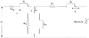
In the electromagnetic structure of the Induction machine, the stator is made of numerous coils with three groups (phases), and is supplied with three phase current. The three coils are physically spread around the stator periphery (space-phase), and carry currents which are out of time-phase. This combination produces a rotating magnetic field, which is a key feature of the working of the induction machine. Induction machines are asynchronous speed machines, operating below synchronous speed when motoring and above synchronous speed when generating. The presence of negative resistance (i.e., when slip is negative), implies that during the generating mode, power flows from the rotor to the stator in the induction machine.
Fig. 1. Per-phase equivalent circuit of the induction machine referred to the stator.
In the above figure, R and X refer to the resistance and inductive
IJSER © 2012
International Journal of Scientific & Engineering Research Volume 2, Issue 2, February-2012 2
ISSN 2229-5518
reactance respectively. Subscripts 1, 2 and m represent stator, rotor values referred to the stator side and magnetizing components, respectively.
Induction machine needs AC excitation current for its running.
The machine is either self-excited or externally excited. Since the excitation current is mainly reactive, a stand-alone system is self- excited by shunt capacitors. In grid-connected operation, it draws excitation power from the network, and its output frequency and voltage values are dictated by the grid. Where the grid capacity of supplying the reactive power is limited, local capacitors can be used to partly supply the needed reactive power [3].
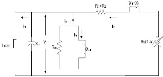
Self-excited induction generator (SEIG) works just like an induction machine in the saturation region except the fact that it has excitation capacitors connected across its stator terminals. These machines are ideal choice for electricity generation in stand-alone variable speed wind energy systems, where reactive power from the grid is not available. The induction generator will self-excite, using the external capacitor, only if the rotor has an adequate remnant magnetic field. In the self-excited mode, the generator output frequency and voltage are affected by the speed, the load, and the capacitance value in farads [3]. The steady-state per-phase equivalent circuit of a self- excited induction generator is shown in the Figure 2.
Fig. 2. Self-excited induction generator with external capacitor.
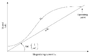
The process of self-excitation in induction machines has been known for many decades [4]. When capacitors are connected across the stator terminals of an induction machine, driven by an external prime mover, voltage will be induced at its terminals. The induced electromotive force (EMF) and current in the stator windings will continue to rise until the steady-state condition is reached, influenced by the magnetic saturation of the machine. At this operating point the voltage and the current will be stabilized at a given peak value and frequency. In order for the self-excitation to occur, for a particular capacitance value there is a corresponding minimum speed [5],[6],[7],[8]. So, in stand-alone mode of operation, it is necessary for the induction generator to be operated in the saturation region. This guarantees one and only one intersection between the magnetization curve and the capacitor reactance line, as well as output voltage stability under load as seen in the Figure 3:
Fig. 3. Determination of stable operation of self-excited induction generator.
At no-load, the capacitor current Ic=V1/Xc must be equal to the magnetizing current Im=V1/Xm. The voltage V1 is a function of Im, linearly rising until the saturation point of the magnetic core is reached. The output frequency of the self-excited generator is, f=1/(2πCXm) and ω=2πf where C is self-exciting capacitance.
There are two fundamental circuit models employed for examining the characteristics of a SEIG. One is the per-phase equivalent circuit which includes the loop-impedance method adopted by Murthy et al [9] and Malik & Al-Bahrani [10], and the nodal admittance method proposed by Ouazene & Mcpherson [11] and Chan [11]. This method is suitable for studying the machine‟s steady-state characteristics. The other method is the dq-axis model based on the generalized machine theory proposed by Elder et al. [6] and Grantham et al. [7], and is employed to analyze the machine‟s transient state as well as steady-state.
Steady-state analysis of induction generators is of interest both from the design and operational points of view. By knowing the parameters of the machine, it is possible to determine the performance of the machine at a given speed, capacitance and load conditions.
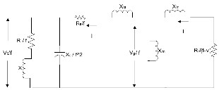
Loop impedance and nodal admittance methods used for the analysis of SEIG are both based on per-phase steady-state equivalent circuit of the induction machine (Fig. 4), modified for the self- excitation case. They make use of the principle of conservation of active and reactive powers, by writing loop equations [9], [10], [13] or nodal equations [11], [12], for the equivalent circuit. These methods are very effective in calculating the minimum value of capacitance needed for guaranteeing self-excitation of the induction generator. For stable operation, excitation capacitance must be slightly higher than the minimum value. Also there is a speed threshold, below which no excitation is possible, called as the cutoff speed of the machine. In the following paragraph, of loop impedance method is given for better understanding.
The per-unit per-phase steady-state circuit of a self-excited induction generator under RL load is shown in Figure 4 [9], [11].
IJSER © 2012
International Journal of Scientific & Engineering Research Volume 2, Issue 2, February-2012 3
ISSN 2229-5518
The process of self-excitation is a transient phenomenon and is better understood if analyzed using a transient model. To arrive at transient model of an induction generator, abc-dq0 transformation is used.
Fig. 4. Equivalent circuit of self-excited induction generator with R-L Load.
Where:
Rs, Rr, R : p.u. per-phase stator, rotor (referred to stator) and load resistance respectively.
Xls, Xlr, X, Xm : p.u. per-phase stator leakage, rotor leakage (referred to stator), load and magnetizing reactances (at base frequency), respectively.
Xsmax : p.u. maximum saturated magnetizing reactance.
C : per-phase terminal-excitation capacitance.
Xc : p.u. per-phase capacitive reactance (at base frequency) of the terminal excitation capacitor.
f, v : p.u.frequency and speed, respectively.
N: base speed in rev/min
Zb: per-phase base impedance
fb: base frequency
Vg, V0 : per-phase air gap and output voltages, respectively.
In the analysis of SEIG the following assumptions were made [9]:
1. Only the magnetizing reactance Xm is assumed to be affected by magnetic saturation, and all other parameters of the equivalent circuit are assumed to be constant. Self- excitation results in the saturation of the main flux and the value of Xm reflect the magnitude of the main flux. Leakage flux passes mainly in the air, and thus these fluxes are not affected to any large extent by the saturation of the main flux.
2. Stator and rotor leakage reactance, in per-unit are taken to be equal. This assumption is normally valid in induction machine analysis.
3. Core loss in the machine is neglected.
For the circuit shown in Figure 4, the loop equation for the current can be written as:
I Z = 0 (1) Where Z is the net loop impedance given by![]()
![]()
![]()
![]()
Z = + + j + (2)
Since at steady-state excitation I ≠0, it follows from (equation 1) that Z = 0 , which implies that both the real and imaginary parts of Z are zeros. These two equations can be solved simultaneously for any two unknowns (usually voltage and frequency). For successful voltage- buildup, the load-capacitance combination and the rotor speed should result in a value such that Xm=Xsmax, which yields the minimum value of excitation capacitance below which the SEIG fails to self-excite.
The abc-dq0 transformation transfers an abc (in any reference frame) system to a rotating dq0 system. Krause et al. [1] noted that, all time varying inductances can be eliminated by referring the stator and rotor variables to a frame of reference rotating at any angular velocity or remaining stationary. All transformations are then obtained by assigning the appropriate speed of rotation to this (arbitrary) reference frame. Also, if the system is balanced the zero component will be equal to zero [1].
A change of variables which formulates a transformation of the
3-phase variables of stationary circuit elements to the arbitrary reference frame may be expressed as [1]:
Fqdos = Ksfabcs (3)
Where:
Fqdos = ;fabcs = ;Ks =
![]()
![]()
![]()
![]()
![]()
![]()
![]()
![]()
is the dummy variable of integration
For the inverses transformation:![]()
![]()
=
![]()
![]()
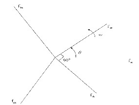
In (equation 3), f can represent voltage, current, flux linkage, or electric charge. The subscript s indicates the variables, parameters and transformation associated with stationary circuits. This above transformation could also be used to transform the time-varying rotor windings of the induction machine. It is convenient to visualize the transformation equations as trigonometric relationships between variables as shown in Figure 5.
IJSER © 2012
International Journal of Scientific & Engineering Research Volume 2, Issue 2, February-2012 4
ISSN 2229-5518
The voltage equations in machine variables can be expressed as
[1]:
Where:
Vabcs = rsiabcs + p abcs (4)
Vabcr = rriabcr + p abcr (5)
Subscript s denotes parameters and variables associated with the stator.
Subscript r denotes parameters and variables associated with the rotor.
Vabcs, Vabcr are phase voltages.
Iabcs, Iabcr are phase currents.
λabcs, λabcr are the flux linkages and p = d/dt.
Fig. 5. Transformation for stationary circuits portrayed bytrigonometric relationships.
The equations of transformation may be thought of as if the fqs and fds variables are directed along axes orthogonal to each other and rotating at an angular velocity of ω, where upon fas, fbs, and fcs (instantaneous quantities which may be any function of time), considered as variables directed along stationary paths each displaced by 1200. Although the waveforms of the qs and ds voltages, currents and flux linkages, and electric charges are dependent upon the angular velocity of the frame of reference, the waveform of the total power is same regardless of the reference frame in which it is evaluated [1].
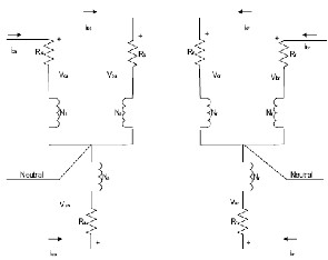
The winding arrangement for a 2-pole, 3-phase, wye-connected, symmetrical induction machine is shown in Figure 6.
By using the abc-dq0 transformation and expressing flux linkages as product of currents and winding inductances, we obtain the following expressions for voltage in arbitrary reference frame [1]:
Vqdos = rsiqdos + ωλdqs + pλqdos (6)
V’qdor = r’ri’qdor + (ω - ωr) λ‘dqr + pλ’qdor (7)
Where:
ω is the electrical angular velocity of the arbitrary frame.
ωr is the electrical angular velocity of the rotor.
(λdqs)T = [λds -λqs 0] ; (λ’dqr)T = [λ‘dr -λ’qr 0]
"‘" denotes rotor values referred to the stator side.
Using the relations between the flux linkages and currents in the
arbitrary reference frame and substituting them in (equations 6) & (equations 7), the voltage and flux equations are expressed as follows:
Vqs = rsiqs + ωλds + pλqs (8) Vds = rsids - ωλqs + pλds (9) V’qr = r’ri’qr (ω - ωr ) λ’dr + pλ’qr (10) V’dr = r’ri’dr - (ω - ωr ) λ’qr + p λ’dr (11) λ qs = Llsiqs + Lm (iqs + i'qr) (12) λ ds = Llsids + Lm (ids + i'dr) (13) λ’qr = L’lriqr + Lm (iqs + i'qr) (14)
’dr = L’lri’dr + Lm (ids + i'dr) (15)
Where:
Fig. 6. Two-pole, 3-phase, wye connected symmetrical induction machine.
The stator windings are identical sinusoidally distributed windings, displaced 1200, with Ns equivalent turns and resistance rs. The rotor is consists of three identical sinusoidally distributed windings, with Nr equivalent turns and resistance rr. Note that positive a, b, c sequence is used in both in Figures 5 and 6.
Lls and Lms are leakage and magnetizing inductances of the stator respectively.
Llr and Lmr are leakage and magnetizing inductances of the rotor respectively.
![]()
Magnetizing inductance, Lm = Lms
The voltage and flux linkage equations suggest the following equivalent circuits for the induction machine:
IJSER © 2012
International Journal of Scientific & Engineering Research Volume 2, Issue 2, February-2012 5
ISSN 2229-5518
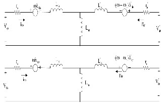
θ(0)=0 (see (equation 3)), the phasor representing phase a variables (with subscript as) is equal to phasor representing qs variables. In other terms, for the rotor reference frame and the stationary frame, fas = fqs , fbs = fas and fcs = fas
Fig. 7. Arbitrary reference-frame equivalent circuits for a 3-phase, symmetrical induction machine
The expression for electromagnetic torque, positive for motor operation and negative for generator operation, in terms of the arbitrary reference variables can be expressed as [1]:![]()
![]()
![]()
![]()
For motor action, Te = m(iqsi’dr – idsi’qr) (16) For generator action, Te = m(idsi’qr – iqsi’dr) (17)
![]()
The torque and speed are related by the following expressions: For the motor operation, Te-motor = J r TD (18)
![]()
For the generator operation, TD = J p r Te-gen (19)
Where:
P: Number of poles.
J: Inertia of the rotor in (Kg m2).
TD: Drive torque in (Nm).
Although the behavior of the induction machine may be described by any frame of reference, there are three which are commonly used [1]. The voltage equations for each of these reference frames can be obtained from the voltage equations in the arbitrary reference frame by assigning the appropriate speed to ω. That is, for the stationary reference frame, ω = 0, for the rotor reference frame, ω = ωr, and for the synchronous reference frame, ω = ωe.
Generally, the conditions of operation will determine the most
convenient reference frame for analysis and/or simulation purposes. The stator reference frame is used when the stator voltages are unbalanced or discontinuous and the rotor applied voltages are balanced or zero. The rotor reference frame is used when the rotor voltages are unbalanced or discontinuous and the stator applied voltages are balanced. The stationary frame is used when all (stator and rotor) voltages are balanced and continuous. In this thesis, the stationary reference frame (ω=0) is used for simulating the model of the self-excited induction generator (SEIG).
In all asynchronously rotating reference frames (ω ≠ ωr) with
As discussed above, the dq model of the SEIG in the stationary reference frame is obtained by substituting ω=0 in the arbitrary reference frame equivalent of the induction machine shown in Figure
7. Figure 8 shows a complete dq-axis model, of the SEIG with load, in the stationary reference frame. Capacitor is connected at the stator terminals for the self-excitation. For convenience, all values are assumed to be referred to the stator side and here after “ „ “ is neglected while expressing rotor parameters referred to the stator [14].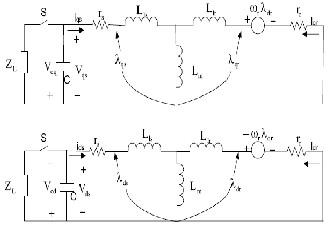
Fig. 8. dq model of SEIG in stationary reference frame (All values referred to stator)
For no-load condition, rearranging the terms after writing loop equations for Figure 8, we obtain the following voltage equations expressed in the form of a matrix [1], [14]:
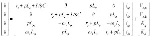 (20)
(20)
Where:
Kd and Kq are constants representing initial induced voltages along the d-axis and q-axis respectively, due to the remaining magnetic flux in the core.
Vcqo and Vcdo are initial voltages in the capacitors
Ls = Lls + Lm and Lr = Llr + Lm.
The above equations can further be simplified in the following manner using (equations 8-15):
In the stationary reference frame (equations 8) can be written as,
Vqs = -Vcq = rsiqs + 0 ds p qs (21)
IJSER © 2012
International Journal of Scientific & Engineering Research Volume 2, Issue 2, February-2012 6
ISSN 2229-5518
Substituting (equation 12) in (equation 21), will result
0 = Vcq + rsiqs + Lspiqs + Lmpiqr (22)
Solving for piqr by substituting (equation 14) and (equation 15) in
(equation 10) yields:![]()
Piqr = (23)
Substituting (equation 23) in (equation 22) results in the final expression for iqs as:![]()
piqs =
A model based on the first order differential equation (equation 25) has been built in the MATLAB/Simulink to observe the behavior of the self-excited induction generator. The parameters used, obtained from [1], are as follows.
Where:
L = LsLr -
) (24)
Table 1: Induction Machine Parameters
All the above mentioned values are referred to the stator side of the induction machine and the value of self-exciting capacitance used is
90 micro farads.
Similarly, the expressions for other current components are obtained
and the SEIG can be represented in a matrix form as:
pI = AI + B (25)
Where:
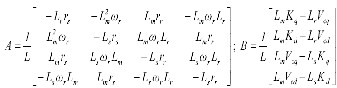
![]()
![]()
I = ;Vcq = ; Vcq =
Any combination of R, L and C can be added in parallel with the self-excitation capacitance to act as load. For example, if resistance R is added in parallel with the self-excitation capacitance, then the term 1/pC in (equation 20) becomes R/(1+RpC). The load can be connected across the capacitors, once the voltage reaches a steady- state value (Grantham et al., 1989), (Seyoum et al., 2003).
The type of load connected to the SEIG is a real concern for voltage regulation. In general, large resistive and inductive loads can vary the terminal voltage over a wide range. For example, the effect of an inductive load in parallel with the excitation capacitor will reduce the resulting effective load impedance (Zeff) (Simoes & Farret, 2004).![]()
Zeff = R + j (26)
This change in the effective self-excitation increases the slope of the straight line of the capacitive reactance (Figure 3), reducing the terminal voltage. This phenomenon is more pronounced when the load becomes highly inductive.
From the previous subsection, it can be said that with inductive loads the value of excitation capacitance value should be increased to satisfy the reactive power requirements of the SEIG as well as the load. This can be achieved by connecting a bank of capacitors, across the load meeting its reactive power requirements thereby, presenting unity power factor characteristics to the SEIG. It is assumed in this thesis that, such a reactive compensation is provided to the inductive load, and the SEIG always operates with unity power factor.
As explained in the previous section, the magnetizing inductance is the main factor for voltage build up and stabilization of generated voltage for theunloaded and loaded conditions of the induction generator (Figure 3). Reference [15] presents a method to determine the magnetizing inductance curve from lab tests performed on a machine. The saturation curve used for the simulation purposes is, obtained from [16] by making use of the B-H saturation curve of the magnetic material (silicon iron 1%), shown in Figure 9.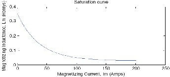
Fig. 9. Variation of magnetizing inductance with magnetizing current.
Using least square curve fit, the magnetizing inductance Lm can be expressed as a function of the magnetizing current Im as follows:
Lm = 1.1*(0.025+0.2974*exp(-0.00271*Im)) (27)
Where,
![]()
Im =
IJSER © 2012
International Journal of Scientific & Engineering Research Volume 2, Issue 2, February-2012 7
ISSN 2229-5518
It must be emphasized that the machine needs residual magnetism so that the self-excitation process can be started. Reference [15] gives different methods to recover the residual magnetism in case it is lost completely. For numerical integration, the residual magnetism cannot be zero at the beginning; its role fades away as soon as the first iterative step for solving (equation 25) has started.
The process of self-excitation can be compared with the resonance phenomenon in an RLC circuit whose transient solution is of the exponential form Kep1t [6], [7]. In the solution, K is a constant, and root p1 is a complex quantity, whose real part represents the rate at which the transient decays, and the imaginary part is proportional to the frequency of oscillation. In real circuits, the real part of p1 is negative, meaning that the transient vanishes with time. With the real part of p1 positive, the transient (voltage) build-up continues until it reaches a stable value with saturation of iron circuit. In other terms, the effect of this saturation is to modify the magnetization reactance Xm, such that the real part of the root p1 becomes zero in which case the response is sinusoidal steady-state corresponding to continuous self-excitation of SEIG.
Any current (resulting from the voltage) flowing in a circuit dissipates power in the circuit resistance, and an increasing current dissipates increasing power, which implies some energy source is available to supply the power. The energy source, referred to above is provided by the kinetic energy of the rotor [7].
With time varying loads, new steady-state value of the voltage is determined by the self-excitation capacitance value, rotor speed and load. These values should be such that they guarantee an intersection of magnetization curve and the capacitor reactance line (Figure 3), which becomes the new operating point.
The following figures show the process of self-excitation in an induction machine under no-load condition.
Fig. 10. Voltage build up in a self-excited induction generator.
From Figures 10 and 11, it can be observed that the phase voltage slowly starts building up and reaches a steady-state value as the magnetization current Im starts from zero and reaches a steady-state value. The value of magnetization current is calculated from the instantaneous values of stator and rotor components of currents (see (equation 27)). The magnetization current influences the value of magnetization inductance Lm as per (3.27), and also capacitance reactance line (Figure 3). From Figures 10-12, we can say that the self-excitation follows the process of magnetic saturation of the core,
and a stable output is reached only when the machine core is saturated.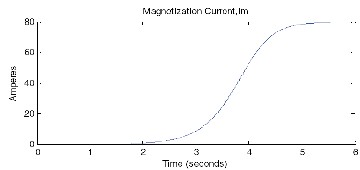
In physical terms the self-excitation process could also be explained in the following way. The residual magnetism in the core induces a voltage across the self-exciting capacitor that produces a capacitive current (a delayed current). This current produces an increased voltage that in turn produces an increased value of capacitor current. This procedure goes on until the saturation of the magnetic field occurs as observed in the simulation results shown in Figures 10 and 11.
Fig. 11. Variation of magnetizing current with voltage buildup.
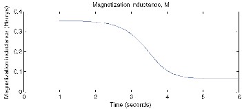
Fig. 12. Variation of magnetizing inductance with voltage buildup.
For the following simulation results the WECS consisting of the SEIG and the wind turbine is driven by wind with velocity of 6 m/s, at no-load. At this wind velocity it can only supply a load of approximately 15 kW. At t=10 seconds a 200 kW load is applied on the WECS. This excess loading of the self-excited induction generator causes the loss of excitation as shown in the Figure 13.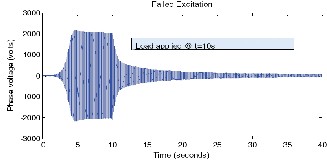
Fig. 13. Failed excitation due to heavy load.
IJSER © 2012
International Journal of Scientific & Engineering Research Volume 2, Issue 2, February-2012 8
ISSN 2229-5518
reduced voltage (Figure 15). The new steady-state values of voltage is determined (Figure 3.3) by intersection of magnetization curve and the capacitor reactance line. While the magnitude of the capacitor reactance line (in Figure 3) is influenced by the magnitude of Im, slope of the line is determined by angular frequency which varies proportional to rotor speed. If the rotor speed decreases then the slope increases, and the new intersection point will be lower to the earlier one, resulting in the reduced stator voltage. Therefore, it can be said that the voltage variation is proportional to the rotor speed variation (Figure 18). The variation of magnetizing current and magnetizing inductance are shown in the Figures 16 and 17 respectively.
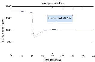
Fig. 14. Generator speed (For failed excitation case)
Figure 14 shows the rotor speed variations with load during the loss of excitation. The increase in load current should be compensated either by increasing the energy input (drive torque) thereby increasing the rotor speed or by an increase in the reactive power to the generator. None of these conditions were met here which resulted in the loss of excitation. It should also be noted from the previous section that there exists a minimum limit for speed (about
1300 rpm for the simulated machine with the self-excitation capacitance equal to 90 micro-farads), below which the SEIG fails to excite.
In a SEIG when load resistance is too small (drawing high load currents), the self-excitation capacitor discharges more quickly, taking the generator to the de-excitation process. This is a natural protection against high currents and short circuits.
For the simulation results shown below, the SEIG-wind turbine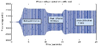
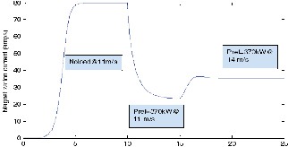
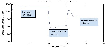
combination is driven with an initial wind velocity of 11m/s at no- load, and load was applied on the machine at t=10 seconds. At t = 15 seconds there was a step input change in the wind velocity reaching a final value of 14 m/s. In both cases the load reference (full load) remained at 370 kW. The simulation results obtained for these operating conditions are as follows:
Fig. 15. SEIG phase voltage variations with load.
For the voltage waveform shown in Figure 15, the machine reaches a steady-state voltage of about 2200 volts around 5 seconds at no-load. When load is applied at t=10seconds, there is a drop in the stator phase voltage and rotational speed of the rotor (shown in Figure 18) for the following reasons.
We know that the voltage and frequency are dependent on load [14]. Loading decreases the magnetizing current Im, as seen in Figure 16, which results in the reduced flux. Reduced flux implies
Magnetization current, Im
Time (seconds)
Fig. 16. Magnetizing current variations with load.
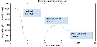
Fig. 17. Magnetizing inductance variations with load.
Figures 16 and 17 verify that the voltage is a function of the magnetizing current, and as a result the magnetizing inductance (see (equation 27)), which determines the steady-state value of the stator voltage.
Fig. 18. Rotor speed variations with load
IJSER © 2012
International Journal of Scientific & Engineering Research Volume 2, Issue 2, February-2012 9
ISSN 2229-5518
Figure 18, shows the variations of the rotor speed for different wind and load conditions. For the same wind speed, as load increases, the frequency and correspondingly synchronous speed of the machine decrease. As a result the rotor speed of the generator, which is slightly above the synchronous speed, also decreases to produce the required amount of slip at each operating point.
As the wind velocity increases from 11m/s to 14m/s, the mechanical input from the wind turbine increases. This results in the increased rotor speed causing an increase in the stator phase voltage, as faster turning rotor produces higher values of stator voltage. The following figures show the corresponding changes in the SEIG currents, WECS torque and power outputs.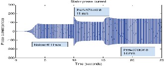
Fig. 19. Stator current variations with load.
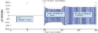
Fig. 20. Load current variations with load.
From Figures 19 and 20, we see that as load increases, the load current increases. When the machine is operating at no-load, the load current is zero. When the load is applied on the machine, the load current reaches a steady-state value of 100 amperes (peak amplitude). With an increase in the prime mover power input, the load current further increases and reaches the maximum peak amplitude of 130 amperes. Also, the stator and load currents will increase with an increase in the value of excitation capacitance. Care should be taken to keep these currents with in the rated limits. Notice that, in the case of motor operation stator windings carry the phasor sum of the rotor current and the magnetizing current. In the case of generator operation the machine stator windings carry current equal to the phasor difference of the rotor current and the magnetizing current. So, the maximum power that can be extracted as a generator is more than 100% of the motor rating [17].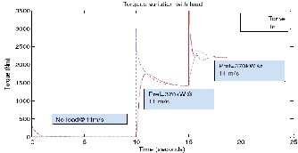
Fig. 21. Variation of torques with load.
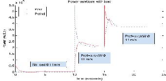
Fig. 22. Output power produced by wind turbine and SEIG.
Equation 17, has been simulated to calculate the electromagnetic torque generated in the induction generator. Figure 21 also shows the electromagnetic torque Te and the drive torque Tdrive produced by the wind turbine at different wind speeds. At t=0, a small drive torque has been applied on the induction generator to avoid simulation errors in Simulink.
Figure 22 shows the electric power output of the SEIG and mechanical power output of the wind turbine. The electric power output of the SEIG (driven by the wind turbine), after t=10 seconds after a short transient because of sudden increase in the load current (Figure 20), is about 210 kW at 11 m/s and reaches the rated maximum power (370 kW) at 14 m/s. Pitch controller limits the wind turbine output power, for wind speeds above 13.5 m/s, to the maximum rated power. This places a limit on the power output of the SEIG also, preventing damage to the WECS. Since, the pitch controller has an inertia associated with the wind turbine rotor blades, at the instant t=15seconds the wind turbine output power sees a sudden rise in its value before pitch controller starts rotating the wind turbine blades out of the wind thereby reducing the value of rotor power coefficient. Note that the power loss in the SEIG is given by the difference between Pout and Pwind, shown in Figure 22.
In this paper the electrical generation part of the wind energy conversion system has been presented. Modeling and analysis of the induction generator, the electrical generator used in this thesis, was explained in detail using dq-axis theory. The effects of excitation capacitor and magnetization inductance on the induction generator, when operating as a stand-alone generator, were explained. From the simulation results presented, it can be said that the self-excited
IJSER © 2012
International Journal of Scientific & Engineering Research Volume 2, Issue 2, February-2012 10
ISSN 2229-5518
induction generator (SEIG) is inherently capable of operating at variable speeds. The induction generator can be made to handle almost any type of load, provided that the loads are compensated to present unity power factor characteristics. SEIG as the electrical generator is an ideal choice for isolated variable-wind power generation schemes, as it has several advantages over conventional synchronous machine.
[1] Paul.C.Krause, Oleg Wasynczuk and Scott D. Sudhoff, “Analysis of Electric
Machinery”, IEEE Press, 1994, ch. 3-4.
[2] Bimal K. Bose, “Modern Power Electronics and Ac Drives”, Pearson
Education, 2003, ch. 2.
[3] Mukund. R. Patel, “Wind Power Systems”, CRC Press, 1999, ch. 6.
[4] E. D. Basset and F. M. Potter, “Capacitive excitation of induction generators,” Trans. Amer. Inst. Elect. Eng, vol. 54, no.5, pp. 540-545, May 1935.
[5] C. F. Wagner, “Self-excitation of induction motors,” Trans. Amer. Inst. Elect.
Eng, vol. 58, pp. 47-51, Feb. 1939.
[6] J. M. Elder, J. T. Boys and J. L. Woodward, “Self-excited induction machine as a small low-cost generator,” Proceedings, IEE, pt. C, vol. 131, no. 2, pp. 33-41, Mar.
1984.
[7] C. Grantham, D. Sutanto and B. Mismail, “Steady-state and transient analysis of self-excited induction generators,” Proceedings, IEE, pt. B, vol. 136, no. 2, pp. 61-68, Mar. 1989.
[8] M. H. Salama and P. G. Holmes, “Transient and steady-state load performance of stand alone self-excited induction generator,” Proceedings, IEE-Elect. Power Applicat. vol. 143, no. 1, pp. 50-58, Jan. 1996.
[9] S. S. Murthy, O. P. Malik and A. K. Tandon, “Analysis of self excited
induction generators,” Proceedings, IEE, pt. C, vol. 129, no. 6, pp. 260-265, Nov.1982. [10] N. H. Malik and A. H. Al-Bahrani, “Influence of the terminal capacitor on the performance characterstics of a self-excited induction generator,” Proceedings, IEE, pt.
C, vol. 137, no. 2, pp. 168-173, Mar. 1990.
[11] L. Ouazene and G. Mcpherson Jr, “Analysis of the isolated induction generator,” IEEE Trans. Power Apparatus and Systems, vol. PAS-102, no. 8, pp.2793-
2798, Aug.1983.
[12] T. F. Chan, “Capacitance requirements of self-excited induction generators,”
IEEE Trans. Energy Conversion, vol. 8, no. 2, pp. 304-311, June 1993.
[13] A. K. Al Jabri and A.I. Alolah, “Capacitance requirements for isolated self- excited induction generator,” Proceedings, IEE, pt. B, vol. 137, no. 3, pp. 154-159, May
1990.
[14] Dawit Seyoum, Colin Grantham and M. F. Rahman, “The dynamic characteristics of an isolated self-excited induction generator driven by a wind turbine,” IEEE Trans. Industry Applications, vol.39, no. 4, pp.936-944, July/August 2003.
[15] M. Godoy Simoes and Felix A. Farret, Renewable Energy Systems-Design and Analysis with Induction Generators, CRC Press, 2004, ch. 3-6.
[16] Theodore Wildi, Electrical Machines, Drives, and Power Systems, Prentice
Hall, Third Edition, 1997, pp. 28.
[17] Rajesh Chathurvedi and S. S. Murthy, “Use of conventional induction motor
as a wind driven self-excited induction generator for autonomous applications,” in IEEE-
24th Intersociety Energy Conversion Eng. Conf., IECEC-89, pp.2051-2055.
[18] Sreedhar Reddy G. (2005), Modeling and Power Management of a Hybrid
Wind-Microturbine Power Generation System, Masters thesis., ch. 3
[19] G. Ofualagba and E.U. Ubeku, “The analysis and modeling of a self-excited induction generator driven by a variable speed wind-turbine” Book-Fundamental and
advanced topics in wind power, InTech, Croatia, 2011, chap 11, pp 249-268.
IJSER © 2012