International Journal of Scientific & Engineering Research, Volume 4, Issue 8, August-2013 51
ISSN 2229-5518
Analysis of Detecting Fault Probability using Variable Linear Load Resistance Switching (VLLRS) Technique in Power Distribution Networks
Ramesh.Palakeerthi, Ramesh.Gamasu
Abstract-This paper presents the analysis of detecting faults probability using Resistance Switching Technique Obtained by using custom power device fed to linear loads. This analysis was detecting the faults in each phase, modified by using resistance switching technique. W ith reference- the resistance switching is used for getting good voltage compensation in sub-systems of power system, to avoid power interruption problems. The entire topology explains by taking custom power device as a reference. This analysis fault simulation is achieved by using Sinusoidal Pulse W idth Modulation Technique. The custom power device is an efficient and effective one, used in major part of the distribution networks. Mainly, the resistance switching is used for modifying the fault conditions in uneven conditions occurring of power systems. The overall topology was modeled and simulated in MATLAB/Simpower System.
Index Terms: Custom power device, Distribution Static Compensator, Faults probability, Resistance Switching, Sinusoidal Pulse
Width Modulation
—————————— ——————————
1 INTRODUCTION
n present days there are many power quality events, such as transients, frequency or power factor variations, and flicker. However, since they are not significantly affected by the performance of the distribution system
but faults very dangerous effecting in very much manner which are not prompt. Faults are Preliminary events that are affecting the power distribution networks like power interruptions and non-linear voltage profile and un- damping load conditions etc [5].
Faults usually occur in a power system due to insulation failure, flashover, physical damage or human error. These faults may either be three phases in nature involving all three phases in a symmetrical manner, or may be asymmetrical where usually only one or two phases may be involved [3]. Faults may also because by either short-circuits to earth or between live conductors, or may be caused by broken conductors in one or more phases [5]. Sometimes simultaneous faults may occur involving both short-circuit and broken-conductor faults (also known as open-circuit faults) [4].
In order to get good power quality in power distribution networks a custom power devices are used. The custom power device is also known as Distribution Static Compensator. This device injects a shunt current to correct the fault condition. Here the custom power device is connected in series or parallel to the digital controlled device for modifying the fault conditions. The fast response of Distribution Static Compensator makes it efficient solution for improving the power quality in distribution system [3].
————————————————
• Mr.P.Ramesh is currently working as an Associate Professor in Department of Electrical& Electronics Engineering, RISE Prakasam Group of Institutions, Ongole (A.P), India. Email: nannu.niky@gmail.com
• Mr.G.Ramesh is currently working as an Assistant Professor in Department
of Electrical& Electronics Engineering, RISE Prakasam Group of
Institutions, Ongole (A.P), India. Email: ramesh.gamasu@gmail.com
A Distribution Static Compensator basically VSC based FACTS controller sharing many similar concept with that of STATCOM used at transmission level [5]. This technique proposes a flexible Distribution Static Compensator system designed to mitigate the voltage sags caused by LG, LL, DLG, 3-Phase and 3-Phase to ground faults [2]. And improve the power quality of the distribution System using Resistance Switching Technique and Reactive power compensation is an important issue in the control of distribution systems. The main reason for reactive power compensation in a system is the voltage regulation increased system stability.
2 EFFECTS OF FAULTS ON POWER SYSTEM
The improvement of power quality during short circuit faults can be achieved in several different ways. Like any other problem that has to be solved, we need first to understand the nature of the problem and it’s effect on sensitive users. The most common short circuit faults in the system – single-phase to ground faults – are characterized by the fact that they introduce a voltage sag in the faulted phase, and at the same time they result in a voltage swell in the two healthy phases. The case of two or three-phase faults is quite different [5]. For three-phase faults all phases experience a voltage sag, while for a two-phase fault - the two faulted phases will have lower voltages, with the healthy phase without a significant change compared to the pre-fault levels. Another factor to be considered in the analysis of short circuit faults is the automatic reclosing. As soon as the fault is cleared, all loads, except the ones connected to the faulted circuit, will have their voltage go back to normal [8]. At the same time during the reclosing interval the loads connected to the faulted line will experience a voltage interruption.
3 DISTRUBUTION STATIC COMPENSATOR AS A CUSTOM POWER DEVICE
IJSER © 2013 http://www.ijser.org
International Journal of Scientific & Engineering Research, Volume 4, Issue 8, August-2013 52
ISSN 2229-5518
The basic electronic block of the Distribution Static Compensator is the voltage source inverter that converts an input dc voltage into a three-phase output voltage at fundamental frequency. These voltages are in phase and coupled with the ac system through the reactance of the coupling transformer [1]. Suitable adjustment of the phase and magnitude of the Distribution Static Compensator output voltages allows effective control of active and reactive power exchanges between the Distribution Static Compensator and the ac system. Therefore the Distribution Static Compensator can be treated as a voltage-controlled source [5].
The VSC connected in shunt with the ac system provides a multifunctional topology which can be used for up to three quite distinct purposes:
1. Voltage regulation and compensation of reactive power;
2. Correction of power factor; and
3. Elimination of current harmonics.
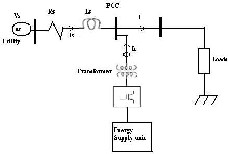
Fig.1. Line Diagram for Distribution Static Compensator
4 VARIABLE LINEAR LOAD RESISTANCE SWITCHING (VLLRS) TECHNIQE
In order to modifying the fault probability in each phase of existing sub-system is achieved by using Resistance Switching Technique. Critically, there is a fault in subsystem was modified by increasing fault resistance in individual phases. Even though by synchronizing Distributed Static compensator also, the system exhibits some small power interruptions are negotiated by the particular system fed to linear and variable load with increasing fault resistance. This technique provides some good compensation is as follows:
1. Good Voltage Profile at end users of distribution networks.
2. Less Power interruptions in distribution.
3. Back to back protection in each phase from fault current
via fault resistance.
4. Effective and Efficient.
5. Excellent feedback facility for desired voltage levels.
This proposed topology explain the orentational
procedure for achieving good voltage compensation
through Distributed Static compensator via Resistance
Switching in each phase of sub-system ,that too liner and
variable.
5 SINUSODIAL PWM BASED CONTROL
The main purpose of the control strategy is to maintain the constant voltage magnitude from point to point of sensitive load which connected under disturbance. This will measure the voltage at load point. The control system only measures the r.m.s voltage at the load point, i.e., no reactive
power measurements are required. The VSC switching strategy’s based on sinusoidal PWM technique which offers simplicity and good response. Since custom power is a relatively low-power application, PWM methods offer a more flexible option than the Fundamental Frequency Switching (FFS) methods favored in FACTS applications [3]. Besides, high switching frequencies can be used to improve the efficiency of the converter, without incurring significant switching losses [6].
5.1 Control Strategy
The controller input is an error signal obtained from the reference voltage and the value rms of the terminal voltage measured. Such error is processed by a PI controller the output is the angle δ, which is provided to the PWM signal generator. It is important to note that in this case, indirectly controlled converter, there is active and reactive power exchange with the network simultaneously: an error signal is obtained by comparing the reference voltage with the rms voltage measure the load point. The PI controller process the error signal generates the required angle to drive the error to zero, i.e., the load rms voltage is brought back to the reference voltage.
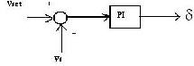
Fig.2.Indirect PI Controller
Here the PI Controller in the test system identifies the error signal and generates the required angle drive the zero. The load voltage is brought back to load rms value and the PWM Generator, the sinusoidal signal Vref compared against the carrier signal in order to generate the signal operation in VSC Valves [5].
The main parameters of the PWM Generator have two important parameters, they are
1. Frequency of Carrier Signal.
2. Modulation Index of PWM.
6 ANALYSIS OF FAULT CURRENT PROBABILITY USING RESISTANCE SWITCHING TECHNIQUE
There are different kinds of fault probability in sub- systems like three phases, three phase-ground, line-line and line-ground, double line-ground etc. In order to implementing the analysis of resistance switching, it is neccesscery for identifying the fault probability then modified.
Let us consider the phase current be the
I phase = I and I normal= I (1)
The nominal voltages for each line is given by
V Line = V Phase /√3 (2)
Here V Rms = V Phase (3)
From equations (2) & (3)
V Rms/Phase = 0.577VPhase (4)
To calculate the phase voltage in each phase for the existing fault resistance R Phase (original) is given by
V Rms/Phase = I Fault/Phase * R Fault (original) (5)
IJSER © 2013 http://www.ijser.org
International Journal of Scientific & Engineering Research, Volume 4, Issue 8, August-2013 53
ISSN 2229-5518
From equation (4), in case of three phase and three phase- Ground faults
The Phase voltage for the Three Phase system in each phase is given by,
V Rms/Phase = 1.733* I Fault/Phase * R Fault (original) (6)
In case of Line-Line, Line-Ground, Double Line-Ground
faults
The Phase Voltage for the individual phase is given by,
V Rms/Phase = I Fault/Phase * R Fault (original) (7)
By applying Resistance Switching Technique, in case of
three phase fault conditions, the resistance at fault condition
modified from one level to another depending up on fault
probability.
Hence the modified Phase voltage in case of the three phase
fault is given by,
V Rms/Phase = 1.733* I Fault/Phase * R Fault (modified) (8)
And the modified phase voltage in case of Line fault conditions after applying Resistance switching technique is given by,
V Rms/Phase = I Fault/Phase * R Fault (modified) ………. (9)
Hence after applying LLRS Technique there will be some
improvement in voltage profile. This technique helps to
keep the system stabilizing and linear one.
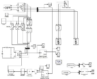
7 POWER SYSTEM SIMULINK MODEL FOR DISTRIBUTION STATIC COMENSATOR OPERATING WITH VLLRS TECHNIQUE
Fig.3. Distribution static compensator connecting with sub-systems in
MATLAB/SIMULINK
8 RESULTS AND DISCURSIONS
The following simulations are carried out for the Sub- system containing Distribution Static Compensator. This result shows the difference between the fault resistance switching with increasing and without increasing probability. Here the entire topology working with SPWM Technique with help of fault resistance switching.
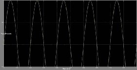
(a)
(b)
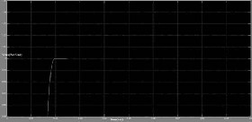
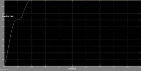
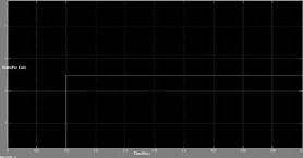
Fig.4.Volatge V rms through Distribution Static Compensator Connecting to Linear Load with Three Phase-Ground Faults (a) W ithout Resistance Switching (b) W ith Resistance Switching.
i. Figure 4(a) Shows Distribution Static Compensator connecting in subsystem consisting fault resistance in three phase-ground fault is 0.35Ω during time period of 0.1sec incase of without resistance switching
Here R Fault (original) = 0.35 Ω and I Fault/Phase = 0.32mA, in t=0.1sec
And V Rms/Phase = 0.194mV.
ii. Figure 4(b) Shows resistance switching case
utilizing for modification of three phase-ground
fault in sub-system ,as follows
Here R Fault (modified) = 0.42 Ω and I Fault/Phase = 0.32mA, in
t=0.1sec
And V Rms/Phase = 0.237mV.
Hence from above V rms comparisons, the voltages in
individual phases are increased by applying resistance
switching. The following tabular form shows variation
before applying switching and after applying switching.
TABLE.1
VOLTAGE PROFILE FOR DIFFERENT SWITCHING CASES WITH THREE PHASE-GROUND FAULT
IJSER © 2013 http://www.ijser.org
International Journal of Scientific & Engineering Research, Volume 4, Issue 8, August-2013 54
ISSN 2229-5518
 (a)
(a)
(a)
(b)
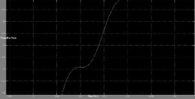
Fig.5.Volatge V rms through Distribution Static Compensator Connecting to Linear Load with Line -Ground Fault (a) W ithout Resistance Switching (b) W ith Resistance Switching.
i. Figure 5(a) Shows Distribution Static Compensator connecting in subsystem consisting fault resistance in line-ground fault is 0.6Ω during time period of
0.5sec in case of without resistance switching,
Here R Fault (original) = 0.6 Ω and I Fault/Phase = 0.4mA, in t=0.5sec And V Rms/Phase = 0.2mV.
ii. Figure 5(b) Shows resistance switching case utilizing for modification of line-ground fault in sub-system, as follows
Here R Fault (modified) = 0.76 Ω and I Fault/Phase = 0.4mA, in t=0.5sec, in same time, and V Rms/Phase = 0.3mV.
Hence from above V rms comparisons, the voltages in individual phases are increased by applying resistance switching.
TABLE.2
VOLTAGE PROFILE FOR DIFFERENT SWITCHING CASES WITH LINE-GROUND FAULT
(b)
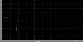
Fig.6.Volatge V rms through Distribution Static Compensator Connecting to Linear Load with Line-Line -Ground Fault (a) W ithout Resistance Switching (b) W ith Resistance Switching.
i. Figure 6(a) Shows Distribution Static Compensator connecting in subsystem consisting fault resistance in line- line-ground fault is 0.9Ω during time period of 0.75sec incase of without resistance switching,
Here R Fault (original) = 0.9 Ω and
I Fault/Phase = 0.28mA, in t=0.75sec
And V Rms/Phase = 0.252mV.
ii. Figure 6(b) Shows resistance switching case utilizing for
modification of line-line-ground fault in sub-system, as
follows
Here R Fault (modified) = 1 Ω and
I Fault/Phase = 0.4mA, in t=0.75sec, in same time.
And V Rms/Phase = 0.4mV.
TABLE.3
VOLTAGE PROFILE FOR DIFFERENT SWITCHING
CASES WITH LINE- LINE -GROUND FAULT
Without Resistance Switching | With Resistance Switching |
R Fault (original) in Ω | V Rms/Phase in mV | R Fault (modified) in Ω | V Rms/Phase in mV |
0.6 | 0.2 | 0.76 | 0.3 |
IJSER © 2013 http://www.ijser.org
International Journal of Scientific & Engineering Research, Volume 4, Issue 8, August-2013 55
ISSN 2229-5518
(a)
(b)
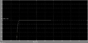
Fig.7.Volatge V rms through Distribution Static Compensator Connecting to Linear Load with Line-Line Fault (a) W ithout Resistance Switching (b) With Resistance Switching.
i. Figure 7(a) Shows Distribution Static Compensator connecting in subsystem consisting fault resistance in line-line-ground fault is 0.9Ω during time period of 0.75sec incase of without resistance switching, Here R Fault (original) = 1.6Ω and
I Fault/Phase = 0.4mA, in t=0.25sec
And V Rms/Phase = 0.64mV.
ii. Figure 7(b) Shows resistance switching case
utilizing for modification of line-line-ground fault
in sub-system, as follows
Here R Fault (modified) = 2.3 Ω and
I Fault/Phase = 0.4mA, in t=0.25sec, in same time.
And V Rms/Phase =0.92 mV.
TABLE.4
VOLTAGE PROFILE FOR DIFFERENT SWITCHING CASES WITH LINE- LINE FAULT
Without Resistance Switching | With Resistance Switching |
R Fault (original) in Ω | V Rms/Phase in mV | R Fault (modified) in Ω | V Rms/Phase in mV |
1.6 | 0.64 | 2.3 | 0.92 |
9 CONCLUSION
In this Paper, a flexible Distribution Static Compensator system designed to alleviate the LG, LL, DLG, 3-Phase and
3-Phase to ground faults and improve the power quality of the Power distribution Network using Resistance Switching Technique .This proposed topology explain the orentational procedure for achieving good voltage
IJSER ©
compensation through Distributed Static compensator via Resistance Switching in each phase of sub-system, that too liner and variable. The Voltage Source Convert (VSC) was implemented with the help of Sinusoidal Pulse Width Modulation (SPWM). The control scheme was tested under a wide range of operating conditions, and it was observed to be very strong in every case. The Resistance switching method can be simulated and developed for provides relatively better voltage capabilities.
10 REFERENCES
[1] O. Anaya-Lara, E. Acha, "Modeling and analysis of custom power systems by PSCAD/EMTDC", IEEE Trans. Power Delivery, vol. 17, no. I, pp. 266-272, January 2002.
[2] A. Hernandez, K. E. Chong, G. Gallegos, and E. Acha, "The implementation of a solid state voltage source in PSCAD/EMTDC", IEEE Power Eng. Rev., pp. 61-62, Dec.
1998.
[3] R. Madhusudan, G.Ramamohanrao,“Modeling and
Simulation of a Distribution STATCOM (D-STATCOM) for
Power Quality Problems-Voltage Sag and Swell Based on
Sinusoidal Pulse Width Modulation (SPWM)”, IEEE,
ICAESM-2012, March30, 31, 2012 and 436.
[4] Heine, Pirjo,”Voltage sag distributions caused by power
system”, IEEE Power& Energy Society, Nov. 2003, Volume:
18, Issue: 4 , Page(s): 1367 – 1373.
[5] Mithilesh Kumar Kanaujia, Dr. S.K. Srivastava , “Power
Quality Enhancement With D-STATCOM Under Different
Fault Conditions” , International Journal of Engineering
Research and Applications (IJERA), Vol. 3, Issue 2, March -
April 2013, pp.828-833.
[6] N. Hingorani, "FACTS-Flexible ac transmission systems",
in Proc. IEE 5th In Conf AC DC Transmission, London, U.K.,
1991, Conf Pub. 345, pp. 1-7.
[7] G.Venkataramana, and B.Johnson, “A pulse width
modulated power line conditioner for sensitive power load
centers”, IEEE Trans. Power Delivery, Vol.12, pp.844-849.apr-
1997.
[8] P.N.K.Sreelatha, J.Praveen, V.Kamaraju, “Voltage
Compensation Using D-STATCOM under Unsymmetrical
Faults in Distribution Systems with Static Power Converter
Fed Dc Motor Load”, International Journal of Engineering
Research and Development, Volume 5, Issue 4 (December
2012), PP. 27-34.
[9] W. Freitas, A. Morelato, "Comparative study between
power system bolckset and PSCAD/EMTDC for transient
analysis of custom power devices based on voltage source
converter", PST, New Orleans, USA, 2003, pp. 1-6.
[10] L.Xu , O.Anaya –Lara , V.G.Agilids , and E. Acha ,”
Development of prototype custom power devices for power
quality enhancement”, in proc.9th ICHQP 2000, Orlando, FL,
Oct.2000,pp.775-783.
[11] N. Mohan, T.M Undeland, and W.P.Robbins, Power

Electronics: Converter Applications and
Design .New York: Wiley, 1995.
BIOGRAPHY
Mr. Ramesh Palakeerthi has received his B.Tech and M.Tech. from JNTU, Hyderabad. He is also a research scholar in the faculty of EEE, Dr. MGR Educational& Research Institute
http://www.ij
International Journal of Scientific & Engineering Research, Volume 4, Issue 8, August-2013 56
ISSN 2229-5518
University, Chennai. His areas of interests are Soft Computing and Special Machines etc. He has life member in ISTE and Member in IAEngg.
Mr.Ramesh.Gamasu received B.Tech in Electrical Engineering from JNT University, Kakinada and Post Graduate Diploma in Energy Management respectively. He is Assistant Professor of Electrical Engineering Department at RISE Group of Institutions. His areas of Interests include Power Quality, Soft computing and Artificial Intelligence.
IJSER © 2013 http://www.ijser.org