International Journal of Scientific & Engineering Research, Volume 6, Issue 3, March-2015 721
ISSN 2229-5518
Analysis and Measurement of Long Term
Evolution Physical Downlink Shared Channel
Raman Trivedi, Rashi Bhargava
Abstract— LTE (Long Term Evolution) is a next generation standard by 3rd Generation Partnership Project (3GPP) consortium. In this paper, the physical layer (PHY) of LTE transceiver is analyzed in downlink transmission for Tactical LTE application. Simulations of the physical layer of LTE transceiver are obtained with the use of LTE System Libraries by AW R Visual System Simulator (VSS) ver.10.04-trial license. The LTE resource grid for transmission on air is generated using Mathworks MATLAB 2014b LTE System Toolbox- Evaluation License. Measurements of PvT, Occupied bandwidth, CCDF and BER are obtained using Texas Instruments Evaluation Modules (EVMs). These results are presented to show the performance of LTE transceivers in Physical Downlink Shared Channel (PDSCH).
Index Terms— CCDF, eNode-B, EVMs, LTE, MIMO, OFDM, PDSCH, PHY, PvT, Simulation.
—————————— ——————————
1 INTRODUCTION
E live in the era of a mobile data revolution that has been witnessed by the mass-market expansion of smartphones, tablets, notebooks, and laptop computers. Users demand services and applications from mobile communica- tion systems that go far beyond mere voice and conventional telephony. The growth in data intensive mobile services and applications such as Web browsing, social networking, and music & video streaming has become a driving force for de- velopment of the next generation of wireless standards. As a result, new standards are being developed to provide the data rates and network capacities necessary to support worldwide delivery of these types of rich multimedia applications while using highly spectrum efficient communication techniques for
mobile cellular technology.
LTE (Long Term Evolution) and LTE-Advanced have been
developed to respond to the requirements of this epoch and to
realize the goal of achieving global broadband mobile com-
munications. The goals and objectives of this evolved system architecture include higher radio access data rates, improved system capacity and coverage, flexible bandwidth operations, significantly improved spectral efficiency, low latency, re- duced operating costs, multi-antenna support, and seamless integration with the Internet and existing mobile communica- tion systems. LTE and LTE-Advanced are representatives of what is known as a fourth generation wireless systems. The overview of the wireless standards evolution is shown in Fig.
1. In the past two decades, we have seen the introduction of various mobile standards, from 2G to 3G to the present 4G,
and the trend would continue further as specifications for 5G
are already getting formalized by international bodies.
————————————————
• Raman Trivedi is currently working as a senior manager,ICT, Tata Advanced
Systems Limited, Noida, India. E-mail: rtrivedi@tataadvancedsystems.com
• Rashi Bhargava is currently pursuing masters degree program in Communica- tion Systems in Christ University, India.E-mail: bhargavarashi31@gmail.com

Fig. 1: Evolution of Wireless Standards
The primary mandate of 2G standards was to support mo- bile telephony and voice applications. The 3G standards marked the beginning of packet-based data revolution and support for Internet applications such as e-mail, Web brows- ing, text messaging and other client-server services on the move. The 4G standards will feature all-IP packet-based net- works and support the explosive demand for bandwidth- hungry applications such as mobile video-on-demand ser- vices. Peak data rate requirements addressed by various wire- less standards over the past two decades are given in Table I.
This paper is organized as follows: In Section II, brief about
LTE Release8 requirements and enabling technologies are giv-
en with the preview of key advancements in Release10 and
beyond. In Section III, the PDSCH transmission is analyzed
and the results are shown. Part A shows the resource grid generation using LTE System Toolbox and also the analysis & simulation results that are carried out with LTE System Librar- ies of AWR’s Visual System Simulator (VSS) for the Physical
Table I: Peak Data Rate Requirements of Various Wireless
IJSER © 2015 http://www.ijser.org
International Journal of Scientific & Engineering Research, Volume 6, Issue 3, March-2015 722
ISSN 2229-5518
Standards 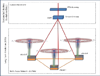
Fig. 2: Flat architecture of LTE
Downlink Shared Channel (PDSCH). Testing and measure- ments conducted using Texas Instrument’s High Speed Ana- log Evaluation Modules for LTE downlink transmitter is pre- sented in Part B. Finally, conclusions are given in Section IV for further discussions.
2 LTE REQUIREMENTS AND ENABLING TECHNOLOGIES
The LTE standard specified by the 3rd Generation Partner- ship Project (3GPP) in Release8, defines the next evolutionary step in 3G technology [9]. LTE offers significant improvements over previous technologies such as Universal Mobile Tele- communications System (UMTS) and High-Speed Packet Ac- cess (HSPA) by introducing a novel physical layer and reform- ing the core network architecture. The main reasons for these changes in the Radio Access Network (RAN) system design are the need to provide higher spectral efficiency, lower delay, and more multi-user flexibility than the currently deployed networks. LTE requirements cover two fundamental compo- nents of the evolved UMTS system architecture: the Evolved Universal Terrestrial Radio Access Network (E-UTRAN) and the Evolved Packet Core (EPC) as shown in Fig. 2.
The enabling technologies of LTE and their evolution in- clude OFDM, MIMO, turbo coding, and dynamic link- adaptation techniques. The LTE radio interface is based on Orthogonal Frequency Division Multiplex (OFDM); OFDM Access (OFDMA) in downlink (DL) and Single Carrier Fre uency Division Multiple Access (SC-FDMA) in uplink (UL). OFDM is an attractive modulation technique in a cellular envi- ronment to combat frequency selective fading channels with a relatively low- complexity receiver. The main rea-
son why LTE selects OFDMA to the multipath fading chan- nel, high spectral efficiency, low-complexity implementation, ability to provide flexible transmission bandwidths and sup-

port for advanced features such as frequency-selective sched- uling, MIMO transmission, and interference coordination etc. However, one of the drawbacks of OFDMA multicarrier transmission is the large variations in instantaneous transmit power due to high peak-to-average power ratio (PAPR), which implicates an inherently inefficient power amplifier and results in higher mobile-terminal power consumption. In UL transmission, the design of complex power amplifiers is espe- cially challenging. As a result, a variant of the OFDM trans- mission known as SC-FDMA is selected in the LTE standard for UL transmission. The Multiple Input Multiple Output (MIMO) methods can improve mobile communication in two different ways: by boosting the overall data rates and by in- creasing the reliability of communication link. In the LTE standard, turbo coding is the only channel coding mechanism used to process user data. Link adaptation is defined as a col- lection of techniques for changing and adapting the transmis- sion parameters of a mobile communication system to better respond to the dynamic nature of the communication chan- nels. Depending on the channel quality, we can use different modulation and coding techniques (adaptive modulation and coding), change the number of transmit or receive antennas (adaptive MIMO), and even change the transmission band- width (adaptive bandwidth) and transmission power (auto- matic transmit power control) as well. All of these methods enable operators to deploy LTE in different regions with dif- ferent frequency bands and bandwidths available to fulfil the following goals for the overall system:
• Improved system capacity and coverage
• High peak data rates
• Low latency (both user-plane and control-plane)
• Reduced operating costs
IJSER © 2015 http://www.ijser.org
International Journal of Scientific & Engineering Research, Volume 6, Issue 3, March-2015 723
ISSN 2229-5518
• Multi-antenna support (SIMO, MIMO, MISO)
• Flexible bandwidth operations and
• Seamless integration with legacy & existing systems
(GSM, UMTS, Wi-Fi, etc.)
LTE documentation was formalized in 2008 (Release8)
and LTE-A documentation (Release10) started from release
2010 onwards. The comparison of key parameters and en-
hancements done in LTE-A w.r.t LTE is given in Table II.
Table II. Comparison of LTE and LTE-Advanced Key
Characteristics
| LTE (Re- lease 8) | LTE Advanced (Release 10) |
Peak Down- link Data Rate | 300 Mb/s | 3 Gb/s |
Peak Uplink Data Rate | 75 Mb/s | 1500 Mb/s |
Peak DL Spectrum Efficiency | 15 bps/Hz | 30 bps/Hz |
Peak UL Spectrum Efficiency | 3.75 bps/Hz | 15 bps/Hz |
Bandwidth | Up to 20 MHz | Up to 100 MHz |
Modulation Schemes | QPSK, 16- QAM, 64- QAM | QPSK, 16-QAM, 64-QAM |
DL Access | OFDMA | OFDMA |
UL Access | SC-FDMA | SC-FDMA |
MIMO Support | Up to 4x4 | Up to 8x8 |
Carrier Ag- gregation | No | Yes |
3 LTE DOWNLINK TRANSMITTER
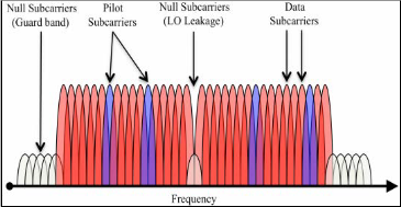
As we know that LTE downlink transmission from eNode- B to User’s Equipment (UE) is based on OFDMA. LTE is in- teroperable with widely used technologies such as GPRS, WCDMA and HSPA. The use of OFDMA, MIMO, Robust Channel Coding, Link Adaptation and Scheduling features of LTE made enable mobile operators deploying this to provide a seamless service and multi-mode devices for customers. OFDM transmissions have a unique signature in the frequency domain because the waveform visually resembles a signal that has been filtered by a brick-wall filter. In fact, we can visual- ize an OFDM signal as a combination of multiple subcarriers as shown in Fig. 3.
Fig. 3: OFDM Signal in the Frequency Domain
3.1 PDSCH Transmitter System Simulations
AWR Corporation is Electronic Design Automation (EDA) Software Company develops markets, sells and support engi- neering software that provides a computer-based environment for the design of hardware for wireless and high speed digital products [12]. AWR's product portfolio includes Microwave Office, Visual System Simulator (VSS), Analog Office, APLAC, AXIEM and Analyst. AWR's worldwide customers include companies involved in the design and development of analog and mixed signal semiconductors, wireless communications equipment, aerospace and defense systems [1] [12]. Math- Works develops MATLAB and Simulink—software that trans- forms the way engineers and scientists think and work. MATLAB® is the high-level language and interactive envi- ronment used by millions of engineers and scientists world- wide. It lets you explore and visualize ideas and collaborate across disciplines including signal and image processing, communications, control systems, and computational finance.
LTE downlink processing is a combination of Downlink Shared Channel processing (DLSCH) and Physical Downlink Shared Channel Processing (PDSCH). Physical layer modeling involves all the processing performed on bits of data that are handed down from the higher layers to the PHY. It describes how various transport channels are mapped to physical chan- nels, how signal processing is performed on each of these channels, and how data are ultimately transported to the an- tenna for transmission.
The LTE transmission scheme provides a time resolution of
12 or 14 OFDM symbols for each subframe of 1ms, depending
on the length of the OFDM cyclic prefix. Regarding the fre-
quency resolution, it provides for a number of resource blocks
ranging from 6 to 100, depending on the bandwidth, each con-
taining 12 subcarriers with 15 kHz spacing. There are essen-
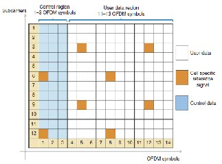
tially three types of information contained in the physical re- source grid. Each resource element contains the modulated symbol of either user data or a reference or synchronization signal or control information originating from various higher- layer channels. Fig. 4 shows the relative locations of the user data, control information, and reference signal in a resource grid as defined for a unicast mode of operation.
IJSER © 2015 http://www.ijser.org
International Journal of Scientific & Engineering Research, Volume 6, Issue 3, March-2015 724
ISSN 2229-5518
ModType<<0
CodebookIndx<<0
N_ID_CELL<<0
RB_PATTERN_INDX<<-1
N_RB_DL<<50
MapperMode<<0
PrecodingMode<<0
FrameType<<0
PORTDOUT P=3
UL_DL_Config << 0
TP PTS_Format << 0
TP ID=DUT_out1
RND_D
SUBCKT ID=S1
NET="PDSCH" ModType=ModType MapperMode=MapperMode
OutLvl_dBm<<0
CarrierFreq_MHz<<1900 LTE_FRMASM ID=A4
MODE=Downlink
NANT=1
SUBCKT ID=S6
NET="OFDMA_MOD" FrameType=FrameType
ID=DUT_in1
SUBCKT ID=S7
NET="DUT"
SUBCKT ID=S10
LTE_FRMDSM ID=A5
MODE=Auto
NANT=Auto
TxOutLvl_dBm=0
TxOutLvl_dBm_vals : { 0,1,2,3,4,5,6,7,8,9,10 }
TxOutLvl_dBm : 0
ID=A1
M=2
RATE=
PrecodingMode=PrecodingMode CodebookIndx=CodebookIndx N_RB_DL=N_RB_DL
ANTPORT=0
N_RB=N_RB_DL N_ID_CELL=N_ID_CELL
N_RB=N_RB_DL OutLvl_dBm=OutLvl_dBm CarrierFreq_MHz=CarrierFreq_MHz
DCoffset=20e-3
AMPIMBAL=0.2
PHAIMBAL=2
NET="OFDMA_DEMOD" FrameType=FrameType N_RB=N_RB_DL
ANTPORT=Auto N_RB= N_ID_CELL=
PORTDOUT
N_ID_CELL=N_ID_CELL
RB_PATTERN_INDX=RB_PATTERN_INDX
LTE
LTE
RB_PATTERN_INDX=
P=1
VSA
ID=EVM1
1 D0 3
2 D1 4
1 D 6
2
1 OFDM 2
Mod.
DUT
1 OFDM 2
DeMod.
1 D 2
3 PORTDOUT
VARNAME="TxOutLvl_dBm" VALUES=TxOutLvl_dBm_vals
RND_D ID=A2
M=2
RATE=
SUBCKT ID=S2
LTE 5
PDSCH
6
Enc.
C LTE
3 P Frame
4 S Asm.
5 R
LTE C Frame P 4
Dsm. S 5
R 6
TP
P=2
ALIGN ID=A6
N= REEVAL= CORRDLY= DLYCOMP=Yes INTRPSPN=0
GAINCOMP=Power PHSCOMP=Rotation & reversal NPOSTPHS=0
TP ID=Ref1
SRC MEAS
RND_D ID=A3
M=2
RATE=
NET="PDCCH"
MapperMode=MapperMode PrecodingMode=PrecodingMode CodebookIndx=CodebookIndx N_RB_DL=N_RB_DL N_ID_CELL=N_ID_CELL
ID=TP1
SMPLPTS=
1 3
2 4
1 2
3
LTE 4
PDCCH
5 6
TP ID=Meas1
SUBCKT ID=S3
NET="P_SCH" NID2=0
LTE 1
P-SCH
5
Enc.
SUBCKT ID=S4
NET="S_SCH" NID1=0
NID2=0
LTE 1
S-SCH
SUBCKT ID=S5
NET="REFSIG" N_RB_DL=26
LTE 1
Ref.Sig.
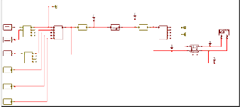
Fig. 6: System Block Diagram of PDSCH Transmitter
Fig. 4: Physical channel and signal content of LTE downlink subframe in unicast mode
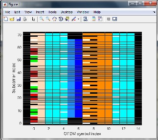
Now, in Fig. 5 we will show the resource grid generated for transmission on air interface before OFDM modulation using LTE System Toolbox. It contains Physical Downlink Control Channel (PDCCH), Physical Downlink Shared Channel (PDSCH), Physical Control Format Indicator Channel (PCFICH), Physical Broadcast Channel (PBCH), Physical Hybrid ARQ Indicator Channel (PHICH) symbols along with Cell-specific Reference (CSR), Primary Synchronization (PSS) and Secondary Synchronization (SSS) signals. We have focussed only on the PDSCH data(2, 3, 4, 11, 12, 13 OFDM symbols in our case) further [3].
Fig. 5: Resource Grid containing PDSCH, PDCCH, PCFICH, PBCH, PHICH symbols, CSR, PSS and SSS signals.
Here, we have modeled LTE PDSCH transmitter using AWR Visual System Simulator (VSS) environment. The system diagram of PDSCH transmitter chain is shown in Fig. 6
The chain of signal processing operations performed in the PDSCH transmitter is composed of following components: LTE signal source, Scrambler, LTE Rate Matching, Modulation Mapper, Layer Mapper, Pre-coder, LTE Frame Assembler, LTE OFDM Modulator, and Signal Analyzer. The processing is completely specified in 3GPP documents describing the multiplexing and channel coding [10] and physical channels and modulation [11].
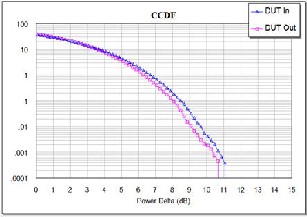
In order to perform Physical layer processing we have to specify a sequence of operations. First, describe channel cod- ing, scrambling, and modulation resulting in modulated sym- bols, then describe the steps in mapping the modulated sig- nals to the resource grid, including mapping the user data, the reference signals, and the control data. Then, we need to speci- fy the MIMO modes that enable multiple antenna transmis- sions which involves specifying layer mapping that describes how many transmit antennas are used in every frame and what precoding transformation is applied to the modulation bits before they are mapped to the resource grids of all trans- mit antennas. Our initial focus has been on unicast services and single antenna port for transmission. Various analysis and graphs for CCDF curve, BER, Occupied Channel BW, IQ Con- stellation [2] [5] etc. were evaluated from the simulation of this system architecture block. A typical simulated CCDF curve and IQ Constellation diagram is shown in Fig. 7.
IJSER © 2015 http://www.ijser.org
International Journal of Scientific & Engineering Research, Volume 6, Issue 3, March-2015 725
ISSN 2229-5518
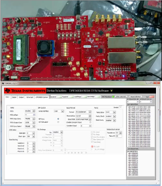
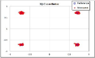
Fig. 7: CCDF Curve and IQ Constellation measured at
DUTIN and DUTOUT ports
3.2 High Speed Analog Evaluation Modules for LTE Physical Layer Test and Analysis
The PDSCH carries the downlink data to each user. It is im- portant to note that the PDSCH can support modulation schemes such as QPSK, 16-QAM, and 64-QAM – depending on the channel conditions between the eNode-B and a specific user [6]. The LTE downlink signal is to use OFDMA and in this scheme, the multiple modulated subcarriers are grouped into resource blocks that can be dedicated to individual users. The combination of 12 subcarriers make up one resource block, and the number of available subcarriers and resource blocks that can be allocated for users varies according to bandwidth configuration as shown in Fig. 8 [8] [3].
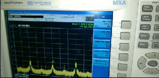
Fig. 8: MXA Signal Capture of the OFDMA Carriers
The LTE downlink transmitter measurements are general- ly designed to ensure interoperability with other cellular and general wireless devices. For example, measurements such as minimum output power and spectrum measurements charac- terize the amount of unintended interference an LTE transmit- ter might produce during transmission. In addition, modula- tion quality is important because its measures the presence of signal impairments that might prevent a UE receiver from demodulating the transmissions. To perform the PDSCH transmitter measurements, connect the Texas Instruments’ Transmitter EVM and Pattern Generator EVM as suggested in EVM’s users’ manual [7] and also shown in Fig. 9.
Fig. 9: Test Set-up for Performing PDSCH Transmitter
Measurements and GUI set-up
To measure the ON-OFF time mask measurement, simply acquire a power-versus-time (PvT) trace of an LTE burst. As we observe in Fig. 10, a time-domain PvT Measurement pro- vides a full power profile of the burst [8] [3].
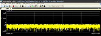
Fig. 10: Power versus Time Measurement
The most fundamental LTE spectral emissions measure- ment, occupied bandwidth, is defined as the bandwidth con- taining 99 % of the total integrated mean power of the trans- mitted spectrum on the assigned channel. As exceeding the bandwidth requirements will cause interference in adjacent channels leading to bit errors in adjacent channel transmis- sions. Spectral flatness is a measure of the flatness of the transmitter chain, including the power amplifier, and is meas- ured in isolation to identify specific frequency-domain re- sponse issues in the transmitter. Fig. 11 shows a spectrum used to calculate the occupied bandwidth and Spectral Flat- ness measurements that have been performed for partially allocated LTE transmission. The occupied bandwidth meas- urement is fundamentally a frequency domain measurement
IJSER © 2015 http://www.ijser.org
International Journal of Scientific & Engineering Research, Volume 6, Issue 3, March-2015 726
ISSN 2229-5518
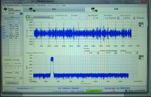
and it requires that we configured the RF signal analyzer to a span that is least 2 times the bandwidth of the transmitted signal. Thus, when using swept-tuned spectrum analyzer, we must use a Gaussian filter.
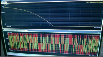
Fig. 12: High Peak-to-Average Waveform in the time domain envelope (bottom) with corresponding CCDF plot
(top)

Fig. 11: Spectral Flatness and Occupied Bandwidth
Measurements for Partially Allocated LTE Transmission
The Error Vector Magnitude (EVM) measurement and Complementary Cumulative Distribution Function (CCDF) are the comprehensive metric of modulation quality that summarizes the effect of a wide range of transmitter impair- ments in the transmitter chain. Fig. 12 shows a CCDF curves that provide critical information about the signals encountered in broadband systems.
These curves also provide meaningful peak-to-average
power data needed to describe the stress on a communication system. The two diagrams shown above illustrate this rela- tionship graphically, mapping the time domain of the wave- form to the CCDF curve. The x-axis shows the signal power in dB above the root mean square (r.m.s) value. The y-axis shows the percentage of time that the signal spends at or above that level.
4 CONCLUSION
Improving measurement accuracy and repeatability first re- quires a working understanding of the instrumentation one might use for LTE transmitter measurements – the RF signal analyzer. In general, one can apply averaging techniques to most transmitter measurements and this technique is com- monly used in measurements such as power, EVM, CCDF, BER, ACPR and ACLR. Also, signal analyzers can obtain the most accurate power, EVM and ACLR results when the peak power of the transmitted signal is just below the clipping level of the instrument. Since the PAPR ranges from 10-14 dB for most LTE downlink transmissions – the ideal reference level is usually identical to the average power level of the transmitted signal.
ACKNOWLEDGMENT
The authors would like to thank Field Application Engineer- ing team of both, AWR Inc. and Texas Instruments Inc., for the various discussions on the topics of this paper.
REFERENCES
Journal article
[1] M.V.S. Lima, C.M.G. Gussen, B.N. Espindola, T.N. Ferreira, W.A. Martins, P.S.R. Diniz, “Open-Source Physical Layer Simulator for LTE Systems,” pre- sented at the IEEE Int. Conf. on Acoustics, Speech and Signal Processing (ICASSP), Kyoto, Japan, pp.2781-2784, Mar. 25-30, 2012.
[2] S.S.A. Abbas, P.A.J. Sheeba, S.J. Thiruvengadam, “Design of Downlink PDSCH Architecture for LTE Using FPGA,” presented at the 2011 IEEE Int. Conf. on Recent Trends in Information Technology (ICRTIT), Chennai, Tamil
Nadu, pp.947-952, June 2011.
Book
[3] Houman Zarrinkoub, 2014, “Understanding LTE with MATLAB: from mathematical foundation to simulation, performance evaluation and imple- mentation,” John Wiley & Sons, Ltd.
[4] Chris Johnson, 2010, “Long Term Evolution in Bullets,” 1st Edition, Cre- ateSpace Independent Publishing Platform.
Proceedings article
[5] Temitope O. Takpor, Francis E. Idachaba, July 2–4, 2014, “Analysis and Simu-
IJSER © 2015 http://www.ijser.org
International Journal of Scientific & Engineering Research, Volume 6, Issue 3, March-2015 727
ISSN 2229-5518
lation of LTE Downlink and Uplink Transceiver,” in Proc. World Congress on
Engineering (WCE), London, U. K.
[6] Jing Zhu, Haitao Li, December 2011, “On the Performance of LTE Physical Downlink Shared Channel,” in Proc. IEEE Int. Conf. on Computer Science and Network Technology (ICCSNT), Harbin Normal University, Harbin, vol.2, pp. 983-986.
World Wide Web
[7] “Texas Instruments User’s Manuals of TSW3084, TSW1400”, http://www.ti.com/general/docs/lit/getliterature.tsp?literatureNumber=sl au433&fileType=pdf, TI Inc., 2014.
[8] “Freescale Semiconductor White Paper: Overview of the 3GPP Long Term Evolution Physical Layer”, http://www.freescale.com/files/wireless_comm/doc/white_paper/3GPPE VOLUTIONWP.pdf, Freescale Semiconductor Inc., 2007.
[9] “3GPP TS 36.101 V8.5.0 (2009-03) Evolved Universal Terrestrial Radio Access
(E-UTRA) User Equipment (UE) radio transmission and reception (Release
8)”, http://www.arib.or.jp/IMT-
2000/V730Jul09/5_Appendix/Rel8/36/36101-851.pdf, March, 2009.
[10] “3GPP (2011) Evolved Universal Terrestrial Radio Access (E-UTRA), Multi- plexing and Channel Coding TS 36.212”, http://www.etsi.org/deliver/etsi_ts/136200_136299/136212/10.01.00_60/ts
_136212v100100p.pdf, April, 2011.
[11] “3GPP (2011) Evolved Universal Terrestrial Radio Access (E-UTRA), Physical Channels and Modulation ver10.0.0 TS 36.211”, http://www.etsi.org/deliver/etsi_ts/136200_136299/136211/10.00.00_60/ts
_136211v100000p.pdf, Jan, 2011.
[12] “AWR Documentation Manual of 10.04 LTE System Libraries”, https://awrcorp.com/download/kb.aspx?file=docs/VSS_Getting_Started.p df, 2012.
IJSER © 2015 http://www.ijser.org