International Journal of Scientific & Engineering Research Volume 4, Issue 1, January-2013 1
ISSN 2229-5518
An Overview of DWDM Technology & Network
Reena Antil, Pinki, Mrs. Sonal Beniwal
Abstract— This article covers functions and applications of DW DM system components. The operation of each component is discussed individually. DW DM terminology like Attenuation, dispersion, and optical signal to noise ratio (OSNR) are measures of optical signal quality and are the key factors involved in DW DM system design and operation. From transmitter to receiver, the quality of the optical signal and the path across which it travels determines if it is successfully detected and recovered at the receiving end. A description of each type of signal measure and its relationship to a DW DM system is given.
Index Terms— Dense wavelength division multiplexing (DW DM),Optical transmitters/receivers, DW DM mux/demux filters.Optical add/drop multiplexers (OADMs), Optical amplifiers, Transponders (wavelength converters), Attenuation, dispersion, and optical signal to noise ratio.
—————————— • ——————————
ense wavelength division multiplexing (DWDM) is an extension of optical networking. DWDM devices com- bine the output from several optical transmitters for
transmission across a single optical fiber. At the receiving end, another DWDM device separates the combined optical signals and passes each channel to an optical receiver. Only one opti- cal fiber is used between DWDM devices (per transmission direction).
Instead of requiring one optical fiber per transmitter and re- ceiver pair, DWDM allows several optical channels to occupy a single fiber optic cable.A key advantage to DWDM is that it's protocol and bit-rate independent. DWDM-based networks can transmit data in IP,ATM,SONET,SDH and Ethernet
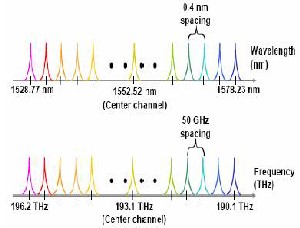
.Therefore, DWDM-based networks can carry different types of traffic at different speeds over an optical channel.Voice transmission, e-mail, video and multimedia data are just some examples of services which can be simultaneously transmitted in DWDM systems.DWDM systems have channels at wave- lengths spaced with 0.4 nm spacing.DWDM is a type of fre- quency division multiplexing (FDM). A fundamental property of light states that individual light waves of different wave- lengths may co-exist independently within a medium. Lasers are capable of creating pulses of light with a very precise wa- velength. Each individual wavelength of light can represent a different channel of information. By combining light pulses of different wavelengths, many channels can be transmitted across a single fiber simultaneously. Fiber optic systems use light signals within the infrared band (1mm to 400 nm wave- length) of the electromagnetic spectrum. Frequencies of light in the optical range of the electromagnetic spectrum are usual- ly identified by their wavelength, although frequency (dis- tance between lambdas) provides a more specific identifica- tion.
————————————————
• Reena Antil is currently pursuing masters degree program in computer engineering in BPSMV, Khanpur kalan, Haryana (India).
• Pinki is currently pursuing masters degree program in computer engineer-
ing in BPSMV, Khanpur kalan, Haryana (India). E-mail: pinkibalhara@gmail.com
• Optical transmitters/receivers
• DWDM mux/demux filters
• Optical add/drop multiplexers (OADMs)
• Optical amplifiers
• Transponders (wavelength converters)
Transmitters are described as DWDM components since they provide the source signals which are then multiplexed. The characteristics of optical transmitters used in DWDM systems is highly important to system design. Multiple optical trans- mitters are used as the light sources in a DWDM sys- tem.Incoming electrical data bits (0 or 1) trigger the modula- tion of a light stream.
Example: a flash of light = 1, the absence of light = 0
Lasers create pulses of light. Each light pulse has an exact wa-
velength (lambda) expressed in nanometers (nm). In an opti-
cal-carrier-based system, a stream of digital information is sent
to a physical layer device, whose output is a light source (an
LED or a laser) that interfaces a fiber optic cable. This device
converts the incoming digital signal from electrical (electrons)
to optical (photons) form (electrical to optical conversion, E-
O). Electrical ones and zeroes trigger a light source that flashes
(for example; light = 1, little or no light =0) light into the core
of an optical fiber. E-O conversion is non-traffic affecting. The format of the underlying digital signal is unchanged. Pulses of light propagate across the optical fiber by way of total internal reflection. At the receiving end, another optical sensor (photo-
diode) detects light pulses and converts the incoming optical signal back to electrical form. A pair of fibers usually connects any two devices (one transmit fiber, one receive fiber).
DWDM systems require very precise wavelengths of light to operate without interchannel distortion or crosstalk. Several individual lasers are typically used to create the individual channels of a DWDM system. Each laser operates at a slightly different wavelength. Modern systems operate with 200, 100, and 50-GHz spacing. Newer systems support 25 GHz spacing and 12.5 GHz spacing is being investigated.
IJSER © 2013 http://www.ijser.org
International Journal of Scientific & Engineering Research Volume 4, Issue 1, January-2013 2
ISSN 2229-5518
Figure 1
This block diagram demonstrates the operation of a one- channel OADM. This OADM is designed to only add or drop optical signals with a particular wavelength (represented by the red light pulse above). From left to right, an incoming composite signal is broken into two components, drop and pass-through. The OADM drops only the red optical signal stream. The dropped signal stream is passed to the receiver of a client device. The remaining optical signals that pass through the OADM are multiplexed with a new add signal stream. The OADM adds a new red optical signal stream, which operates at the same wavelength as the dropped signal. The new optical signal stream is combined with the pass- through signals to form a new composite signal.
Multiple wavelengths (all within the 1550 nm band) created by multiple transmitters and operating on different fibers are combined onto one fiber by way of an optical filter (multiplex- er filter). The output signal of an optical multiplexer is re- ferred to as a composite signal.At the receiving end, an optical drop filter (demultiplexer) separates all of the individual wa- velengths of the composite signal out to individual fibers. The individual fibers pass the demultiplexed wavelengths to as many optical receivers. Typically, mux and demux (transmit and receive) components are contained in a single enclosure. Optical mux/demux devices can be passive. Component sig- nals are multiplexed and demultiplexed optically, not elec- tronically, therefore no external power source is required.
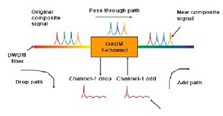
FIG. 3
The block diagram shows in figure 2 is bidirectional DWDM
operation. N light pulses of N different wavelengths carried
by N different fibers are combined by a DWDM mux. The N signals are multiplexed onto a pair of optical fiber. A DWDM demultiplexer receives the composite signal and separates each of the N component signals and passes each to a fiber. The transmitted and receive signal arrows represent client- side equipment. This requires the use of a pair of optical fi- bers; one for transmit, one for receive.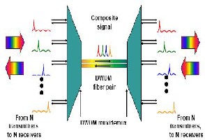
Fig 2. Mux/demux (transmit/receive) components
Optical amplifiers (OAs) boost the amplitude or add gain to
optical signals passing on a fiber by directly stimulating the photons of the signal with extra energy.They are “in-fiber” devices. OAs amplify optical signals across a broad range of wavelengths. This is very important for DWDM system appli- cation.Erbium-doped fiber amplifiers (EDFAs) are the most commonly used type of in-fiber optical fibre.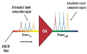
Figure:4
IJSER © 2013 http://www.ijser.org
International Journal of Scientific & Engineering Research Volume 4, Issue 1, January-2013 3
ISSN 2229-5518
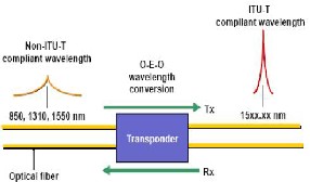
Transponders convert optical signals from one incoming wa- velength to another outgoing wavelength suitable for DWDM applications. Transponders are optical-electrical-optical (O-E- O) wavelength converters. A transponder performs an O-E-O operation to convert wavelengths of light. Within the DWDM system a transponder converts the client optical signal back to an electrical signal (O-E) and then performs either 2R (reampl- ify, reshape) or 3R (reamplify, reshape, and retime) functions. The block diagram shows bi-directional transponder opera- tion. A transponder is located between a client device and a DWDM system. From left to right, the transponder receives an optical bit stream operating at one particular wavelength (1310 nm). The transponder converts the operating wavelength of the incoming bitstream to an ITU-compliant wavelength. It transmits its output into a DWDM system.On the receive side (right to left), the process is reversed. The transponder receives an ITU-compliant bit stream and converts the signals back to the wavelength used by the client device.
• The individual DWDM lambdas are either mapped to the required output type through the transponder or they are passed directly to client-side equipment.
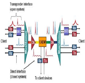
Figure6
Attenuation is the loss of signal level reported in decibels (dB).Attenuation occurs when impurities in the core and clad- ding absorb energy from the optical signal. Attenuation is also caused by light “leaking” from the cladding.
Figure:5
Impurities in optical fiber absorb energy from a passing light sig- nal, and is measured in decibels (dB) of loss per length (kilome- ter) of optical fiber (dB/km). Typical losses are 0.3 dB/km (1550 nm) and 0.5 dB/km (1310 nm).
The following steps describe the block diagram shown below:
• The transponder accepts input in the form of a standard
single-mode or multimode laser pulse. The input can come
from different physical media and different protocols and traf-
fic types.
• The wavelength of the transponder input signal is
mapped to a DWDM wavelength.
• DWDM wavelengths from the transponder are multip-
lexed with signals from the direct interface to form a com-
posite optical signal which is launched into the fiber.
• A post-amplifier boosts the strength of the optical signal as it leaves the multiplexer.
• An OADM is used at a remote location to drop and add bit streams of a specific wavelength.
• Additional optical amplifiers can be used along the fiber span (line amplifier) as needed.
• A pre-amplifier boosts the signal before it enters the de- muliplexer.
• The incoming signal is demultiplexed into individual
DWDM wavelengths.
Optical imperfections (air gaps, etc.) found in fiber splices and connectors absorb or deflect energy from a passing light sig- nal. Splice and connector loss is measured in decibels (dB) per splice or connector. Typical values are 0.05 dB/splice and 0.25 dB/connector.
Loss encountered when multiple optical signals are multiplexed together or when a multiplexed signal is demultiplexed. Also, loss related to inserting a device into the optical path, e.g. relating to passing an OADM for a non-affected wavelength. Insertion loss is measured across an optical device (mux/demux, OADM, etc.
IJSER © 2013 http://www.ijser.org
International Journal of Scientific & Engineering Research Volume 4, Issue 1, January-2013 4
ISSN 2229-5518
Dispersion is the spreading out of a signal as it travels down the fiber. Dispersion results in distortion of the signal which limits the bandwidth of the fiber. Two general types of dispersion affect DWDM systems. One of these effects, chromatic dispersion, is linear while the other, polarization mode dispersion (PMD), is nonlinear. Chromatic dispersion occurs because different wavelengths propagate at different speeds. The effect of chromatic dispersion increases as the square of the bit rate. Polarization mode dispersion (PMD) is caused by ovality of the fiber shape as a result of the manufacturing process or from external stressors. Because stress can vary over time, PMD, unlike chromatic dispersion, is subject to change over time. PMD is generally not a problem at speeds below OC-192.
OSNR is a measure of the ratio of signal level to the level of system noise. As OSNR decreases, bit detection and recovery errors increase. OSNR is measured in decibels (dB).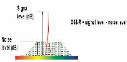
Figure:7
Signal strength reduces over distance in an optical fiber and may need boosting periodically with optical amplifiers, yet the optical gain associated with these amplifiers must be balanced against the additional noise each amplifier introduces. Noise is created by transmitter lasers and optical amplifiers in particu- lar – without optical amplifiers, OSNR will hardly ever affect the bit error rate’ (BER) level. Optical amplifiers amplify the optical signals as well as the undesirable noise. The weaker the signal level or the greater the noise level leads to a lower OSNR. Receivers require acceptable levels of OSNR to distin- guish signals from system noise.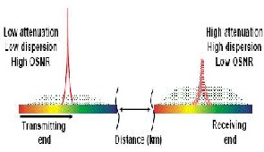
Figure 8
The article provides an overview of DWDM networks and its current technologies. Analyses of applications and roles of current network protocols in the future DWDM frameworks are also provided. It seems clear that DWDM will reshape communication networks, but the current network architec- tures and protocols will play their roles in the future DWDM based framework. Because of the switching simplicity and bandwidth availability through DWDM. The interaction of all the components associated with a DWDM system is critical to system design. From transmitter to receiver, the strength (power level) and quality (OSNR, dispersion) of every optical signal must be maintained.Optical amplifiers extend the reach of DWDM systems by overcoming losses due to attenuation, but could cause OSNR problems. Dispersion compensation devices and dispersion compensated fiber can reduce the amount of dispersion of a particular span, hence increasing the transmission distance.
DWDM - Dense Wavelength Division Multiplexing
WDM - Wavelength Division Multiplexing
OSNR - Optical signal to noise ratio
O-E-O - optical-electrical-optical
OA - Optical amplifiers
EDFA - Erbium-doped fiber amplifiers
PMD - Polarization mode dispersion
It is a great pleasure for me to record my deep sense of grati- tude and appreciation to Mrs.Sonal Beniwal, the Paper super- visor for his valuable guidance, keen interest, encouragement and friendly discussion during the paper of the present re- search work. She has guided my endeavours and encouraged me to explore the joys of learning.
[1] G. P. Agrawal, Lightwave Technology: Telecommunication Systems
(Wiley, Hoboken, NJ, 2005.
[2] G. P. Agrawal, Lightwave Technology: Components and Devices
(Wiley, Hoboken, NJ, 2007).
[3] G. P. Agrawal, Fiber-Optic Communication Systems, (Wiley, Hobo- ken, NJ, 2009).
[4] R. Ramaswami and K. Sivarajan, Optical Networks (Morgan, San
Francisco, 2009).
[5] I. P. Kaminow, et al, “A Wideband All-Optical WDM Network”, IEEE Journal on Selected Areas in Communications, Vol.14, No. 5, June 1996, pp. 780 - 799.)
[6] Melián, B., Laguna, M., and Moreno, J.A., "Capacity expansion of fiber optic networks with WDM systems: Problem formulation and comparative analysis", Computers and Operations Research, 31(3) (2004) 461-472.
IJSER © 2013 http://www.ijser.org