International Journal of Scientific & Engineering Research Volume 4, Issue 2, February-2013 1
ISSN 2229-5518
An Empirical Study on Route Reservation in
Inter-Networks
Dr. Dhrub Prasad, Dr. Kumar Balwant Singh, Shafiqul Abidin
Abstract— W hile it is obvious that transmission without route reservation is suitable for a wired data network such as Internet, it is not clear whether this is true in the case of ad hoc wireless networks. To the best of our knowledge, this has not been studied in the literature. In this paper, we investigate the performance of two switching paradigms: reservation-based (RB) and non-reservation based (NRB). In an NRB scheme, no reservation is required before data transmission, data transmission can begin as soon as a source discovers a route. This is the typical scheme used for most of the protocols proposed in the literature. In contrast, in an RB scheme, a source reserves uniquely intermediate nodes on a route for relaying its message.
Intermediate nodes agree to relay traffic of one source only while the route is reserved. To the best of our knowledge, such a switching scheme has never been considered in the literature. Although a few analytical models which take into account delay and physical layer characteristics ex- ist for NRB ad hoc wireless networks [1, 2], no analytical models have been reported for RB schemes. In this paper, we quantify the performanc e tradeoff between these two schemes in terms of throughput, delay, and maximum tolerable node speed. The main purpose of this research is to compare the two schemes - route reservation based and non route reservation based schemes. Further, it compares the performance of the two schemes by drawing the chart between the time taken to transfer the message and type of reservation.
Index Terms— Reservation-Based Swtiching, Non-Reservation – Bsed Switching, Route Discovery, Multi Hop, Access Delay.
—————————— ——————————
t is obvious that transmission without route reservation is suitable for a wired data network such as Internet, it is not clear whether this is true in the case of ad hoc wireless net- works. To the best of our knowledge, this has not been studied in the literature. In this paper, we investigate the performance of two switching paradigms: reservation-based (RB) and non- reservation based (NRB). In an NRB scheme, no reservation is required before data transmission; data transmission can begin as soon as a source discovers a route. This is the typical scheme used for most of the protocols proposed in the litera- ture. In contrast, in an RB scheme, a source reserves uniquely
intermediate nodes on a route for relaying its message [3].
Intermediate nodes agree to relay traffic of one source only while the route is reserved. To the best of our knowledge, such a switching scheme has never been considered in the litera- ture. Although a few analytical models which take into ac- count delay and physical layer characteristics exist for NRB ad hoc wireless networks [2–4], no analytical models have been reported for RB schemes. In this paper, we quantify the per- formance tradeoff between these two schemes in terms of good put, delay, and maximum tolerable node speed.
————————————————
Dr. Dhrub Prasad is associated as a Director with the Department of Science & Technology, Govt of Bihar, Patna, India
Dr. Kumar Balwant Singh is currently associated with the Department of
Physics, Government Polytechnic, Dharbhanga, Bihar, India. E-mail: kbsphys- ics@yahoo.co.in
Shafiqul Abidin is pursuing his Ph. D. in Computer Science / IT from B.R. A.
Bihar University, Muzaffarpur, India, E-mail: shafiqulabidin@yahoo.co.in
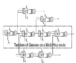
In the case of NRB switching, there is no reservation of a route prior to data transmission. As opposed to an RB scheme, in this scenario, multi-hop routes can overlap. In particular, a node can serve as a relay for more than one route. In other words, when a node receives a message from another node Tandem of Queues on a Multi-Hop route (i.e., it acts as a re- lay), it places such message in its own queue (intermingled with its own generated messages) [4]. The messages in the queue are transmitted sequentially (i.e., the priority given to relay and new locally generated messages is the same).
As in the case of RB switching, we assume that the message generation process is Poisson and that the message length is exponentially distributed with average value Lm. Unlike the case with RB switching (where the relay nodes give absolute priority to the relayed messages, stopping to serve their own messages), each multi-hop route is a tandem of queues, and the whole network can also be viewed as a tandem of queues. As a result, Burke’s theorem can be applied, and each indi- vidual node can be modeled as an M/M/1 queue.
The principle of operation of an RB scheme is fairly simple. Prior to data transmission, a source node reserves a multi-hop route to the destination through a route discovery process. Once an intermediate node agrees to relay traffic for a particular source in the network, it cannot initiate a session or relay messages for any other source until the ongoing session is over. The source node releases the route after the session is terminat- ed. We emphasize that this reservation pertains to node processing but not to the shared common radio channel. In other words, reservation of a multi-hop route does not give any node an exclusive access to the shared
IJSER © 2013 http://www.ijser.org
International Journal of Scientific & Engineering Research Volume 4, Issue 2, February-2013 2
ISSN 2229-5518
radio channel (in terms of frequency bands, time slots, or spreading codes).
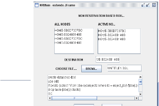
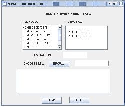
The proposed system is to evaluate the performance of the Route Reservation in inter-networking. In an RB (Reservation Based) scheme, a source first reserves a multi-hop route to its destination. It reserves intermediate nodes before the actual transmission begins. The reserved intermediate nodes are re- quired to relay only the message generated by the specific source. This gives the source an exclusive access to the path to the destination.
The main objective of the project is to investigate the perfor- mance of two switching paradigms: reservation-based (RB) and non-reservation based (NRB). In an NRB scheme, no res- ervation is required before data transmission; data transmis- sion can begin as soon as a source discovers a route. This is the typical scheme used for most of the protocols proposed in the literature. In contrast, in an RB scheme, a source reserves uniquely intermediate nodes on a route for relaying its mes- sage. Intermediate nodes agree to relay traffic of one source only while the route is reserved. To the best of our knowledge, such a switching scheme has never been considered in the lit- erature.
The system is designed to develop a system that can transfer the message in less time, to develop a non route reservation based scheme and to develop a route reservation scheme. Fi- nally the system compares the route reservation and non route reservation based schemes by flashing a chart between time taken to transfer the message and type of reservation.
This research paper comprises three main modules - Non- Route Based scheme, Route-Based scheme and Comparison Module.
The conceptual model of an NRB wireless network is shown in Figure 1.
In order to evaluate the performance of an RB switching scheme, we make the following assumptions. In the case of NRB switching, there is no reservation of a route prior to data transmission. As opposed to an RB scheme, in this scenario, multi-hop routes can overlap. In particular, a node can serve as a relay for more than one route. In other words, when a node receives a message from another node (i.e., it acts as a relay), it places such message in its own queue (intermingled with its own generated messages). The messages in the queue are transmitted sequentially (i.e., the priority given to relay and new locally generated messages is the same). As in the case of RB switching, we assume that the message generation process is Poisson and that the message length is exponential- ly distributed with average value Lm.
Unlike the case with RB switching (where the relay nodes give absolute priority to the relayed messages, stopping to serve their own messages), each multi-hop route is a tandem of queues, and the whole network can also be viewed as a tan- dem of queues. As a result, Burke’s theorem can be applied, and each individual node can be modeled as an M/M/1 queue [5]. The conceptual model of an NRB wireless network is shown in Figure 1.
Each node in the network generates messages according to a Poisson process with average arrival rate λm (dimension: [msg/s]). While a node is acting as a relay, it still generates its own messages, which are buffered for future transmission. The message length Lm is exponentially distributed with av- erage value Lm (dimension: [b/msg]). Considering a fixed transmission data rate Rb (dimension: [b/s]), the message du- ration is therefore exponentially distributed with mean value equal to Lm/Rb.
Since intermediate nodes on a multi-hop route serve only one source node at a time, simultaneously active multi-hop routes are disjoint. In addition, given that each multi-hop route has a certain average length, there exists a maximum average num- ber, denoted by Cs, of simultaneously active routes.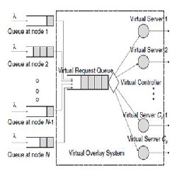
If the number of nodes wishing to activate a multi-hop route is larger than Cs, then some nodes have to wait before they can activate the route. The amount of time that a node has to wait be- fore it can acti- vate a route will
be referred to as “access de- lay.”
Fig. 1. Non-Route Scheme
IJSER © 2013 http://www.ijser.org
International Journal of Scientific & Engineering Research Volume 4, Issue 2, February-2013 3
ISSN 2229-5518
Fig. 2. Route-Based Reservation Scheme
The route activation process can be described by a conceptual “virtual request queue” which regulates requests from all sources (see Figure 1). In this sense, one can imagine that the first message of the queue at each source node is immediately forwarded to the virtual request queue. As it will be shown later, the virtual server models the waiting time that a source experiences, after discovering a route, before being able to activate it. Each possibly active multi-hop route corresponds, in this conceptual model, to a virtual server which takes care of the messages in the virtual request queue. The number of servers corresponds to the maximum average number Cs of disjoint multi-hop routes in the network.
The time spent by a message in the virtual request queue cor- responds to the time necessary for intermediate nodes to be- come available. Therefore, a message in the virtual request queue might not be served in the order in which it arrives. However, according to little’s theorem, the average delay in the system will be the same regardless of the specific queuing discipline.
The total delay between generation and complete transmission of a message, at each source node, is obtained by adding three terms: (i) the time spent in the node’s own queue (denoted by WRBo ); (ii) the time spent in the virtual request queue (denot- ed by WRBv ); and (iii) the time spent in the server (denoted by TRBs ). In particular, the queue at each node can be mod- elled as an M/G/1 queue with service time τRB = WRBv + TRBs.
The combination of the virtual request queue and the Cs vir- tual servers will be denoted as “virtual overlay system.” In particular, there are N flows of information at its input, com- ing from the N nodes. Invoking Klein rock’s independence approximation, the total arrival process at the input of the re- quest queue can be modeled as Poisson with rate Nλm. Hence, it follows that the virtual overlay system shown in Figure 1 can be modelled as an M/M/Cs/∞/N system.
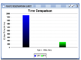
In Figure 3, the average packet delay is shown as a function of the packet generation rate λp where λp _ λmLM/lp, for differ- ent values of the number of nodes. As expected, it is observed that the delay increases as the traffic load increases. The re- sults in Figure 3 show that an RB scheme performs better than an NRB scheme up to a critical load, which makes the delay of the RB scheme go to infinity very rapidly. Below this critical
load, the delay of an RB scheme is very insensitive to the traf- fic load. The overall behavior of an RB scheme can therefore be characterized as bimodal: either almost constant, with respect to traffic load, or infinite. Figure 3 illustrates that the delay of an RB scheme is lower than that of an NRB scheme by more than one order of magnitude for every considered node spatial density. Based on these results, we predict that, in a realistic network, an RB scheme is still likely to outperform an NRB scheme in terms of delay. Nonetheless, the maximum traffic that an RB scheme can support is lower than that of the RB scheme. This is due to the constraint on the disjoint routes.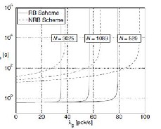
Fig. 3. Comparison of two Switching Schemes
In Figure 3, the average packet delay is shown as a function of the packet generation rate λp where λp _ λmLM/lp, for differ- ent values of the number of nodes. As expected, it is observed that the delay increases as the traffic load increases. The re- sults in Figure 3 show that an RB scheme performs better than an NRB scheme up to a critical load, which makes the delay of the RB scheme go to infinity very rapidly. Below this critical load, the delay of an RB scheme is very insensitive to the traf- fic load. The overall behavior of an RB scheme can therefore be characterized as bimodal: either almost constant, with respect to traffic load, or infinite. Figure 3 illustrates that the delay of an RB scheme is lower than that of an NRB scheme by more than one order of magnitude for every considered node spatial density. Based on these results, we predict that, in a realistic network, an RB scheme is still likely to outperform an NRB scheme in terms of delay. Nonetheless, the maximum traffic that an RB scheme can support is lower than that of the RB scheme. This is due to the constraint on the disjoint routes.
It is important to note, however, that the difference between the maximum traffic loads that the two schemes can support decreases as the node spatial density increases. In other words, an RB switching scheme becomes preferable, delay- wise, in dense ad hoc wireless networks.
IJSER © 2013 http://www.ijser.org
International Journal of Scientific & Engineering Research Volume 4, Issue 2, February-2013 4
ISSN 2229-5518
When some node S originates a new packet destined to some other node D, it places in the header of the packet a source route giving the sequence of hops that the packet should fol- low on its way to D. Normally, S will obtain a suitable source route by searching its Route Cache of routes previously learned, but if no route is found in its cache, it will initiate the Route Discovery protocol to dynamically find a new route to D. In this case, we call S the initiator and D the target of the Route Discovery.
For example, Figure 4 illustrates an example Route Discovery, in which a node A is attempting to discover a route to node E. To initiate the Route Discovery, A transmits a ROUTE RE- QUEST message as a single local broadcast packet, which is received by (approximately) all nodes currently within wire- less transmission range of A. Each ROUTE REQUEST message identifies the initiator and target of the Route Discovery, and also contains a unique request id, determined by the initiator of the REQUEST. Each ROUTE REQUEST also contains a rec- ord listing the address of each intermediate node through which this particular copy of the ROUTE REQUEST message has been forwarded. This route record is initialized to an emp- ty list by the initiator of the Route Discovery.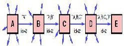
Fig. 4. Route Discovery Example
When another node receives a ROUTE REQUEST, if it is the target of the Route Discovery, it returns a ROUTE REPLY message to the initiator of the Route Discovery, giving a copy of the accumulated route record from the ROUTE REQUEST; when the initiator receives this ROUTE REPLY, it caches this route in its Route Cache for use in sending subsequent packets to this destination. Otherwise, if this node receiving the ROUTE REQUEST has recently seen another ROUTE RE- QUEST message from this initiator bearing this same request id, or if it finds that its own address is already listed in the route record in the ROUTE REQUEST message, it discards the REQUEST. Otherwise, this node appends its own address to the route record in the ROUTE REQUEST message and prop- agates it by transmitting it as a local broadcast packet (with the same request id).
In returning the ROUTE REPLY to the initiator of the Route Discovery, such as node E replying back to A in Figure 1, node E will typically examine its own Route Cache for a route back to A, and if found, will use it for the source route for delivery of the packet containing the ROUTE REPLY. Otherwise, E may
perform its own Route Discovery for target node A, but to avoid possible infinite recursion of Route Discoveries, it must piggyback this ROUTE REPLY on its own ROUTE REQUEST message for A. It is also possible to piggyback other small data packets, such as a TCP SYN packet [Postel 1981b], on a ROUTE REQUEST using this same mechanism. Node E could also simply reverse the sequence of hops in the route record that it trying to send in the ROUTE REPLY, and use this as the source route on the packet carrying the ROUTE REPLY itself. For MAC protocols such as IEEE 802.11 that require a bi- directional frame exchange as part of the MAC protocol [IEEE
1997], this route reversal is preferred as it avoids the overhead of a possible second Route.
Discovery and it tests the discovered route to ensure it is bi- directional before the Route Discovery initiator begins using the route. However, this technique will prevent the discovery of routes using uni-directional links. In wireless environments where the use of uni-directional links is permitted, such routes may in some cases be more efficient than those with only bi- directional links, or they may be the only way to achieve con- nectivity to the target node.![]()
Fig. 4. Route Maintenance Example
When initiating a Route Discovery, the sending node saves a copy of the original packet in a local buffer called the Send Buffer. The Send Buffer contains a copy of each packet that cannot be transmitted by this node because it does not yet have a source route to the packet’s destination. Each packet in the Send Buffer is stamped with the time that it was placed into the Buffer and is discarded after residing in the Send Buffer for some timeout period; if necessary for preventing the Send Buffer from overflowing, a FIFO or other replacement strategy can also be used to evict packets before they expire.
While a packet remains in the Send Buffer, the node should occasionally initiate a new Route Discovery for the packet’s destination address. However, the node must limit the rate at which such new Route Discoveries for the same address are initiated, since it is possible that the destination node is not currently reachable. In particular, due to the limited wireless transmission range and the movement of the nodes in the network, the network may at times become partitioned, mean- ing that there is currently no sequence of nodes through which a packet could be forwarded to reach the destination. Depend- ing on the movement pattern and the density of nodes in the network, such network partitions may be rare or may be common.
IJSER © 2013 http://www.ijser.org
International Journal of Scientific & Engineering Research Volume 4, Issue 2, February-2013 5
ISSN 2229-5518
If a new Route Discovery was initiated for each packet sent by a node in such a situation, a large number of unproductive ROUTE REQUEST packets would be propagated throughout the subset of the ad hoc network reachable from this node. In order to reduce the overhead from such Route Discoveries, we use exponential back-off to limit the rate at which new Route Discoveries may be initiated by any node for the same target. If the node attempts to send additional data packets to this same node more frequently than this limit, the subsequent packets should be buffered in the Send Buffer until a ROUTE REPLY is received, but the node must not initiate a new Route Discovery until the minimum allowable interval between new Route Discoveries for this target has been reached. This limita- tion on the maximum rate of Route Discoveries for the same target is similar to the mechanism required by Internet nodes to limit the rate at which ARP REQUESTs are sent for any sin- gle target IP address
When originating or forwarding a packet using a source route, each node transmitting the packet is responsible for confirm- ing that the packet has been received by the next hop along the source route; the packet is retransmitted (up to a maxi- mum number of attempts) until this confirmation of receipt is received. For example, in the situation illustrated in Figure 4, node A has originated a packet for E using a source route through intermediate nodes B, C, and D. In this case, node A is responsible for receipt of the packet at B, node B is responsible for receipt at C, node C is responsible for receipt at D, and node D is responsible for receipt finally at the destination E. This confirmation of receipt in many cases may be provided at no cost to DSR, either as an existing standard part of theMAC protocol in use (such as the link-level acknowledgement frame defined by IEEE 802.11 [IEEE 1997]), or by a passive acknowl- edgement [Jubin 1987] (in which, for example, B confirms re- ceipt at C by overhearing C transmit the packet to forward it on to D). If neither of these confirmation mechanisms are available, the node transmitting the packet may set a bit in the packet’s header to request a DSR-specific software acknowl- edgement be returned by the next hop; this software acknowl- edgement will normally be transmitted directly to the sending node, but if the link between these two nodes is uni- directional, this software acknowledgement may travel over a different, multi-hop path.
has in its Route Cache another route to E (for example, from additional ROUTE REPLYs from its earlier Route Discovery, or from having overheard sufficient routing information from other packets), it can send the packet using the new route im- mediately.
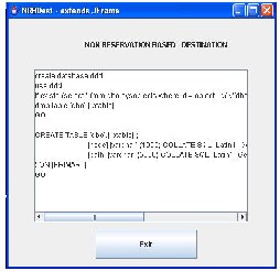
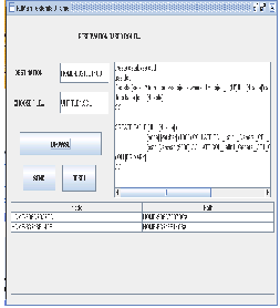
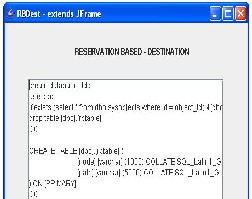
Application is programmed using JAVA to prove aforemen- tioned facts and to compare the schemes. Few screen shots have been shown in the paper, after executing the application different screen shots have been flashed.
If the packet is retransmitted by some hop the maximum number of times and no receipt confirmation is received, this node returns a ROUTE ERROR message to the original sender of the packet, identifying the link over which the packet could not be forwarded. For example, in Figure 5, if C is unable to deliver the packet to the next hop D, then C returns a ROUTE ERROR to A, stating that the link from C to D is currently “broken.” Node A then removes this broken link from its cache; any retransmission of the original packet is a function for upper layer protocols such as TCP. For sending such a re- transmission or other packets to this same destination E, if A
IJSER © 2013 http://www.ijser.
International Journal of Scientific & Engineering Research Volume 4, Issue 2, February-2013 6
ISSN 2229-5518
The results of the analytical framework show that RB schemes are appropriate for real-time applications, such as voice and video due to its ability to guarantee relatively low delay. On other hand an NRB scheme is more appropriate for delay in- sensitive applications such as data transmission, because it can achieve higher network utilization. Further, it is important to understand that if one uses a different MAC protocol and / or one does not use a separate control channel for route discov- ery, for instance, then the results obtained might be very dif- ferent from those derived in this implementation.
The results of the analytical framework show that RB schemes are appropriate for real-time applications, such as voice and video due to its ability to guarantee relatively low delay. On other hand an NRB scheme is more appropriate for delay in- sensitive applications such as data transmission, because it can achieve higher network utilization. Further, it is important to understand that if one uses a different MAC protocol and / or one does not use a separate control channel for route discov- ery, for instance, then the results obtained might be very dif- ferent from those derived in this implementation.
[1] Liming Wei and Deborah Estrin. The trade-o_s of multicast trees and algorithms. In International Conference on Computer Commu- nications and Networks, August 1994.
IJSER © 2013 http://www.ijser.org
International Journal of Scientific & Engineering Research Volume 4, Issue 2, February-2013 7
ISSN 2229-5518
[2] William T. Zaumen and J.J. Garcia-Luna Aceves.Dynamics of distributed shortest-path routing algorithms. In Proceedings of ACM SIGCOMM '91, 1991.
[3] S. E. Deering. Host extensions for IP multicasting. Internet Re- quest for Comments 1112, August 1988.
[4] C. Alaettino_glu and A. U. Shankar. An approach to hierarchical and inter-domain routing with on-demand tos and policy resolu- tion. In Proceedings of 1993 Inter-national Conference on Network Protocols, San Fran- cisco, pages 72{79, October 1993.
[5] S. Sibal and A. DeSimone. Controlling alternate rout-ing in gen- eral-mesh packet ow networks. Proceedings of ACM SIGCOMM
'94: 136-147.
[6] E. M. Royer and C.-K. Toh, “A review of current routing protocols for ad hoc mobile wireless networks,”
[7] P. Gupta and P. R. Kumar, “The capacity of wireless networks,”
IEEE Trans. Inform. Theory.
Websites
http://java.sun.com/ http://java.sun.com/j2se/docs/books/tutorial/index.html http://www.java2s.com
http://dev.java.net http://www.answers.com http://www.Google.com
IJSER © 2013 http://www.ijser.org