s T P

International Journal of Scientific & Engineering Research, Volume 4, Issue 2, Fabuary-2013
ISSN 2229-5518
An Efficient comparison of MIMO OFDM Channel
Estimation Algorithm
Dr.MINAL SAXENA, Prof. NAVNEET KAUR, Ms. SWATI PATEL
Abstract- A multiple-input multiple-output (MIMO) wireless communication system combined with the orthogonal frequency division multiplexing (OFDM) modulation technique, which can achieve reliable high data rate transmission over broadband wireless channels. Channel state information for MIMO Channel systems based on pilot aided arrangement is included in this paper. The estimation of channel at pilot frequencies with conventional Least Square (LS) and Minimum Mean Square (MMSE) estimation algorithms is carried out through Matlab simulation. The performance of MIMO OFDM is evaluated on the basis of Bit Error Rate (BER) and Mean Square Error (MSE) level. Further enhancement of performance can be achieved through maximum diversity Space Time Block Coding (STBC) and Maximum Likelihood Detection at transmission and reception ends respectively. MMSE estimation has been shown to perform much better than LS for the MIMO system using pilot carriers.
.
—————————— ——————————
FDM (Orthogonal Frequency Division Multiplex- becoming a very popular multi-carrier modulation technique for transmission of signals over wireless channels. OFDM divides the high-rate series stream into parallel lower rate data and which helping to eliminate Inter Symbol Interference (ISI). It also allows the band- width of Subcarriers to overlap without Inter Carrier In- terference (ICI) as long as the modulated carriers are or- thogonal. OFDM therefore is considered as an efficient modulation technique for broadband access in a disper- sive environment.[1] In this new information age, Wire- less systems continue to make every effort for ever higher data rates. This goal is particularly challenging for sys- tems that are power, bandwidth, and complexity limited. High data rate and strong reliability systems are becom- ing the dominant factors for a successful exploitation of commercial networks in wire-less communication. MIMO-OFDM (multiple input multiple output orthogo- nal frequency division multiplexing), a new wireless broadband technology, has gained great popularity for its capability of high rate transmission, reliability and its robustness against multi-path fading and other channel impairments. The arrangement of multiple antennas at the transition end and reception end results increase in the diversity gain refers the quality of signal and multi- plexing gain refers the transmission capacity. Space time block coding used in this paper to transmit multiple cop- ies of a data stream across a number of antennas and to exploit the various received versions of data to improve reliability of data transfer. The major challenge faced in MIMO-OFDM systems is how to obtain the channel state information accurately and promptly for coherent detec- tion of information symbols. In the graph we have shown the advantage of channel estimation compared to that of
no channel estimation for the different SNR levels.
The training-based method channel estimation can
be performed by either block type pilots where pilot
tones are inserted into all frequency bins within periodic
intervals of OFDM blocks or by comb pilots where pilot tones are inserted into each OFDM symbol symbols with a specific period of frequency bins. In an OFDM system
,the transmitter modulates the message bit sequence in to PSK/QAM symbols ,performs IFFT on the symbols to convert them in to time domain signals, and sends them throughout the wireless channel, The channel characteris- tic distort the received signal, so to recover the transmit- ted bits at receiver side, the channel effect must be esti- mated and compensated. (8-10). Each subcarrier can be regulated as an independent channel ,as long as no iner- carrier interference occurs, and preserved orthogonality among subcarriers. The orthogonality allows each sub- carrier component of the received signal to be expressed at the subcarriers. So the transmitted signal can be recov- ered by estimating the channel response just at each sub- carrier. In general the channel can be estimated by using a preamble or pilot symbol known to both transmitter and receiver, which employs various interpolation tech- niques to estimate the channel response of the subcarriers between pilot tones. In general data signal as well as training signal both can be used for channel estimation. In order to choose the channel estimation technique for the OFDM system under consideration, much different aspect of implementations, including the required per- formance, computational complexity, and time variation of the channel must be taken in to account. Further, this signal model is transformed into a linear form suitable for the LS (least square) and MMSE (minimum mean square
IJSER © 2013
International Journal of Scientific & Engineering Research, Volume 4, Issue 2, Fabuary-2013
ISSN 2229-5518
Data Source Channel
Encoder
Didital
Modulator
MIMO Encoder
P S I /
/ F S
P F
S I P
/ F / P F S
Timing and frequency
synch.
Data Sink Channel
Decoder
Digital Demod- ulator
MIMO Decoder
P F S
/ F /
s T P
Channel
Estimation
P F S
/ F /
s T P![]()
Figure 1: MIMO-OFDM System model
error) Estimation algorithm.MMSE has been shown to perform much better than LS.
The organization of the paper is as follows. Section 2 describe the system models of MIMO OFDM systems. Section 3 provided the performances of LS and MMSE algorithms in both the systems, simulation results & graphs are presented in Section 4 Conclusion is given in Section 5
Fig. 1 depicts a block diagram of the MIMO OFDM sys- tem. We consider MIMO–OFDM systems with two transmit antennas and two receive antennas. The total number of subcarriers is N. Basically, the MIMO-OFDM transmitter has Nt parallel transmission paths which are very similar to the single antenna OFDM system, each branch performing serial-to-parallel conversion, pilot
insertion, N-point IFFT and cyclic extension before the final TX signals are up-converted to RF and transmitted. It is worth noting that the channel encoder and the digital modulation, in some spatial multiplexing systems, can also be done per branch, where the modulated signals are then space-time coded. Subsequently at the receiver side, the CP is removed and N-point FFT is performed per receiver branch. Next, the transmitted symbol per TX antenna is combined and outputted for the subsequent operations like digital demodulation and decoding. Final- ly all the input binary data are recovered with certain BER. As a MIMO signalling technique, Nt different sig- nals are transmitted simultaneously over Nt X Nr trans- mission paths and each of those Nr received signals is a combination of all the Nt transmitted signals and the dis- torting noise. It brings in the diversity gain for enhanced system capacity as we desire[7] . MIMO OFDM system model which is consist of xt ;t=0….N-1, transmitted sig-
IJSER © 2013
International Journal of Scientific & Engineering Research, Volume 4, Issue 2, Fabuary-2013
ISSN 2229-5518
nals and yt received signals. The transmitted signals xt are taken from multi amplitude signal constellation The channel impulse response of the system is calculated us- ing the equation given below.![]()
g(t)= . (t-![]() )…………..(1)
)…………..(1)
Where is the sampling interval,![]() is the delay,
is the delay, ![]() is the amplitude.
is the amplitude.
The received signal is given as
Y=XFg+n![]()
Where X is the matrix element of x on its diagonal and
x= and n is the noise. n=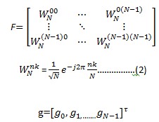
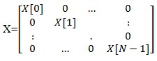
Training symbols can be used for channel estimation, usually providing a good performance. However, their transmission efficiencies are reduced due to the required overhead of training symbols such as preamble or pilot tones that are transmitted in addition to data symbols. The least-square (LS) and minimum-mean-square-error (MMSE) techniques are widely used for channel estima- tion when training symbols are available [9]. We assume that all subcarriers are orthogonal. Then the training symbols for N subcarriers can be represented by Matrix,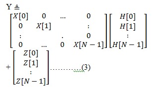
Where X[k] denotes apilot tone at the kth subcarrier with E{X[k]}=0 and Var{Z[k]}=σ2z ,k=0,1,2…,N-1. Channel gain is H[k] for each subcarrier k ,the received training signal y[k] can be represented by,
Y=XH+Z
Where H is a channel vector given as H=[H[0],H[1],…,H[N-1]]T and Z is a noise vector given as Z= [Z[0],Z[1],…,Z[N-1]]T with Var{Z[k]}=σ2z
,k=0,1,2…,N-1.
The least square channel estimation method finds esti- mate Ĥ in such a way that the following function can be minimized.![]()
J(Ĥ)= 2 ……………..(4)
= ( )H(![]() )
)
=YHY-YHXĤ-ĤHXHY+ĤHXHXĤ
derivation of the function with respect to Ĥ to zero,
![]() …(5)
…(5)
we have XHXĤ= XHY, which gives the solution to the LS
channel estimation as,
IJSER © 2013
International Journal of Scientific & Engineering Research, Volume 4, Issue 2, Fabuary-2013
ISSN 2229-5518
ĤLS = (XHX)-1XHY = X-1Y…………….(6)
![]()
The mean square error (MSE) of this LS channel estimation is given as
MSELS=E{(H-ĤLS)H(H-HLS)}
=E{(H-X-1Y)H(H-X-1Y)}
= E{(X-1Z)H(X-1Z)}
= E{ZH(XXH)-1Z}
![]() ……………(7)
……………(7)
The MSE of LS in above equation is inversely proportional to
the SNR ![]() /
/![]() , which implies that it may be subject to noise enhancement, Due to its simplicity the LS is widely used for channel estimation.
, which implies that it may be subject to noise enhancement, Due to its simplicity the LS is widely used for channel estimation.
In MMSE channel estimation weight matrix W define Ĥ![]() W
W![]() , refer fig 2 MSE of the channel estimate Ĥ is given as,
, refer fig 2 MSE of the channel estimate Ĥ is given as,
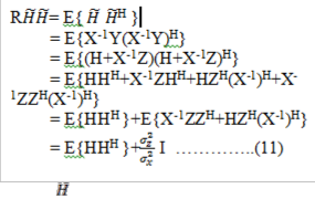
And RH is the crosscorelation matrix between the true channel vector and temporary channel estimate vector in the frequency domain. 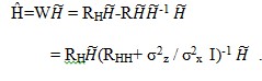 …(12)
…(12)
![]()
…..(8)
+
H
W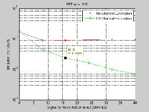
![]()
Ĥ=W
Then the MMSE Channel Estimation method finds abetter linear estimate in terms of W in such a way that the MSE is minimized.
The orthogonality principal state that the estimation error vector e=H-Ĥ is orthogonal to ![]() ,
,
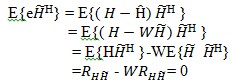 …(9)
…(9)
RAB is the auto correlation matrix of N×N matrices of A
and B![]()
(10)
Where R is the auto correlation matrix of ![]() is given as
is given as
IJSER © 2013
International Journal of Scientific & Engineering Research, Volume 4, Issue 2, Fabuary-2013
ISSN 2229-5518
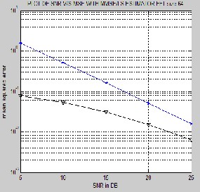

FFT SIZE | SNR | MSE(LS) | MSE (MMSE) |
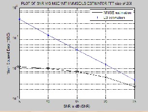
64 | 15 | 0.1563 | 0.03133 |
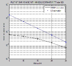
128 | 15 | 0.1704 | 0.02208 |
IJSER © 2013
International Journal of Scientific & Engineering Research, Volume 4, Issue 2, Fabuary-2013
ISSN 2229-5518
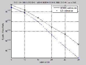
FFT SIZE | SNR | SER(LS) | SER (MMSE) |
64 | 20 | 0.3784 | 0.3046 |
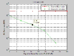
128 | 20 | 0.8297 | 0.7337 |
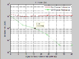
256 | 20 | 1.885 | 1.885 |
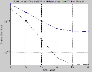
In this paper, we propose to evaluate the performance of LS and LMMSE estimation techniques. For Downlink systems under the effect of the IFFT size, channel length, SNR and BER. The cyclic prefix inserted at the beginning of each OFDM symbol is usually equal to or longer than the channel length in order to suppress ICI and ISI. However, the CP length can be shorter than the channel length because of some unforeseen behavior of the channel. Simulation results show that LS channel estimation is better than that of NO channel estimation. When LS is compared to MMSE estima- tion MMSE shows better performance than LS. As the IFFT size increased the significant improvement in BER but in- creasing the IFFT size will result in more computational load. LS is easy to implement and MMSE is a bit complex but gives significant increase in SNR value when compared to LS length, the LMMSE performs better.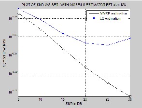
[1] MIMO-OFDM Channel Estimation Using Pilot CarriesInterna tional
Journal of Computer Applications (0975 – 8887) Volume 2 – No.3, May
2010, Kala Praveen Bagadi Ph.D Student ,Dept. of Electrical Engineering NIT Rourkela, India Prof. Susmita Das Associate Professor Dept. of Electri- cal Engineering NIT Rourkela, India
[2] Ramjee Prasad, “OFDM for Wireless Communications Systems”, Artech
House, Inc. Publications.
[3] Ezio Biglieri, Robert Calderbank, Robert Calderbank, Anthony Constan- tinides, Andrea Goldsmith, Arogyaswami Paulraj, H. Vincent Poor, “MIMO Wireless Communications”, Cambridge Press.
[4] Channel Estimation Techniques Based on Pilot Arrangement in OFDM
Systems, Sinem Coleri, Mustafa Ergen, Anuj Puri, and Ahmad Bahai, IEEE TRANSACTIONS ON BROADCASTING, VOL. 48, NO. 3, SEPTEMBER
2002 223
[5] Broadband MIMO-OFDM Wireless CommunicationsGORDON L.
STÜBER, FELLOW, IEEE, JOHN R. BARRY, MEMBER, IEEE,STEVE W. MCLAUGHLIN, SENIOR MEMBER, IEEE, YE (GEOFFREY) LI, SENIOR MEMBER, IEEE,MARY ANN INGRAM, SENIOR MEMBER, IEEE, AND THOMAS G. PRATT, MEMBER, IEEE0018-9219/04$20.00 © 2004 IEEE,
PROCEEDINGS OF THE IEEE, VOL. 92, NO. 2, FEBRUARY 2004
IJSER © 2013
International Journal of Scientific & Engineering Research, Volume 4, Issue 2, Fabuary-2013
ISSN 2229-5518
[6] MIMO-OFDM Wireless Communications with MATLAB_ Yong Soo Cho, Jaekwon Kim, Won Young Yangand Chung G. Kang_ 2010 John Wiley & Sons (Asia) Pte Ltd
[7] MIMO-OFDM COMMUNICATION SYSTEMS: CHANNEL ESTIMA-
TION AND WIRELESS LOCATION by Zhongshan Wu B.S., Northeastern
University, China, 1996 M.S., Louisiana State University, US, 2001 May 2006 [8] Cimini, L.J. (1985) Analysis and simulation of a digital mobile channel using orthogonal frequency-divisionmultiplexing. IEEE Trans. Commun., 33(7),
665–675.
[9] Tufvesson, F. and Maseng, T. (May 1997) Pilot assisted channel estimation
forOFDMin mobile cellular systems. IEEE VTC’97, vol. 3, pp. 1639–1643.
[10] van de Beek, J.J., Edfors, O., Sandell, M. et al. (July 1995) On channel estima- tion in OFDM systems. IEEE VTC’95, vol. 2, pp. 815–819.
IJSER © 2013