M(s)=KpE(s)+
International Journal of Scientific & Engineering Research, Volume 6, Issue 4, April-2015 90
ISSN 2229-5518
1S.NARASIMHA, 2M.SUSHAMA
.
—————————— ——————————
The world electricity demand is increasing day by day. To meet electricity demands with help of natural energy source are not a only sufficient to meet this loads. In extant to meet the load demands by using renewable energy sources and cogeneration systems are one solution. The multilevel inverter is a DC to AC converter circuit that generates the voltage without resort to energy storage device and trans- formers by using multiple DC sources and witching elements. In conventional inverter circuits, the suppression of harmoni cs is
control using SVPWM.
This is the combination of proportional and integral control action. Mathematically it can be represented by equation [2]
m(t)=Kp e(t)+KpKi∫0 𝑒(𝑡)𝑑𝑡………………..(1)
Laplace transform of equation (1)
possible by pulse width modulation, and the harmonic contents can
be reduced when using a multilevel configuration [3].
![]()
M(s)=KpE(s)+
𝐾𝑝
E(s)=E(s)�1 +![]()
�Kp
𝑆𝑇𝑖
1
𝑆𝑇𝑖
The cogeneration systems using Solar, wind energy and fuel cells
![]()
𝑀(𝑠)
= Kp
𝐸(𝑠)
𝑆𝑇𝑖
![]()
� ………………………….. (2)
have become widespread. In such systems, the generated power is
converted into a DC voltage, stored in batteries, and then converted into an AC voltage by inverter circuits [18].
In these type of power plants, the generated power is not constant
always and unsteady, and large voltage fluctuations .Thus far, volt- age stabilization has been achieved by the introducti on of booster circuits, and maintain the inverter output voltage magnitude constant or rated value even though input DC voltage magnitude fluctuating conditi on[3],[4,[5],][6].
In this paper, we analyzed the control method for the simplifi cation of control cal culations, improving the voltage
Utilization factor of multilevel inverters without transformer and reduce the total harmonic distorti ons.
And also we have introduced a new control algorithm in which the superposition ratio is varied according to DC volt- age fluctuations. An approach [19],[20] to determine the opti- mum switching angles in varying DC sources is to calculate the switching angles using PI, Fuzzy logic control and PSO
————————————————
• S.NARASIMHA, Research Scholar , Dept. of Electrical and electron- ic engineering, JNTUH, India, 500085, snarasimha.999@gmail.com
• M.SUSHAMA, Professor ,Dept. of Electrical and electronic engi- neering, JNTUHCEH, India, 500085, m73sushama@yahoo.com
In equation (2) both parameters Kp and Ti are adjustable. Ti is
called integral time, Kp is proportional coefficient. In integral
control action the actuating signal consists of proportional
error signal with integral of the error signal.
Fig1.Block diagram of PI control
In proportional control action, the output of the controller is
proportional to error[2]. When the error is zero, the controller
output is constant. In this action the gain kp and proportional
band are inversely proportional to each other. In integral con- trol action, the output of the controller is changed at a rate which is proportional to the actuating error signal e(t).
2.1 Output voltage tracking control
The foll owing has been obtained from the fundamental Equations for a three-phase three-wire system, and from the Relationship between the line voltages and phase voltages [8],[18].
𝑉𝑎𝑏 + 𝑉𝑏𝑐 +𝑉𝑐𝑎 = 0 ......................... (3)
IJSER © 2015 http://www.ijser.org
International Journal of Scientific & Engineering Research, Volume 6, Issue 4, April-2015 91
ISSN 2229-5518
𝑉𝑎𝑛 + 𝑉𝑏𝑛 + 𝑉𝑐𝑛 = 0 ....................... (4)
Relational expression between line voltage and phase voltages
the following equations are obtained.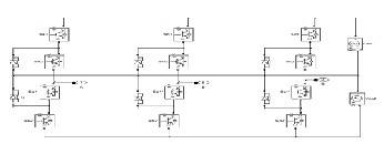
𝑉𝑎𝑏 = 𝑉𝑎𝑛 − 𝑉𝑏𝑛
𝑉𝑏𝑐 = 𝑉𝑏𝑛 −𝑉𝑐𝑛 ................................ (5)
𝑉𝑐𝑎= 𝑉𝑐𝑛 − 𝑉𝑎𝑛
When (3) (4) and (5) are arranged in 𝑉𝑎𝑛 they become as
follows
𝑉𝑎𝑛 = −𝑉𝑏𝑛 − 𝑉𝑐𝑛 ........................... (6)
𝑉𝑎𝑛 = 𝑉𝑏𝑛 +𝑉𝑎𝑏 ......................... (7)
𝑉𝑎𝑛 = 𝑉𝑐𝑛 − 𝑉𝑐𝑎
By adding both sides of three equations following equa-
tion is deduced.
3𝑉𝑎𝑛 = 𝑉𝑎𝑏 − 𝑉𝑐𝑎
By similarly operation on other phase
1
Fig.3: Three-level diode clamped inverter
𝑉𝑎𝑛 =
𝑉𝑏𝑛 =![]()
![]()
(𝑉𝑎𝑏 − 𝑉𝑐𝑎 )
(𝑉𝑏𝑐 − 𝑉𝑎𝑏 ) ....................... (8)![]()
1
This fuzzy logic controller is 3- level system so it has two in-
puts, n-level system has (n-1) inputs and (𝑠 − 1)2 rules are
𝑉𝑐𝑛 =
(𝑉𝑐𝑎 − 𝑉𝑏𝑐)
Phase voltage of 𝑉𝑎𝑛 , 𝑉𝑏𝑛 , 𝑉𝑐𝑛 are converted into two phase AC
𝑉𝛼 and Vβ by using following matrix.
1 1
𝑉𝛼![]()
![]()
![]()
1 − −![]()
![]()
![]()
2 2 2
𝑉𝑎𝑛
�𝑉𝛽 �=�
�
0 √3
2
− √3
2
![]()
![]()
� �𝑉𝑏𝑛 � .................... (9)
𝑉𝑐𝑛
In addition 𝑉𝑜𝑢𝑡 is calculated by synthesizing the vector of
𝑉𝛼 , 𝑉𝛽 .![]()
𝑉𝑜𝑢𝑡 = �|𝑉𝛼 |2 + �𝑉𝛽 �
............................... (10)
𝑉𝑎 , 𝑉𝑏 , 𝑉𝑐 𝑜𝑓 each phase are expressed by following equations
𝑉𝑎 = 𝑉𝑝𝑖 [(1 + 𝛼)𝑠𝑠𝑠Ө + 𝛼𝑠𝑠𝑠3Ө]![]()
2
![]()
𝑉𝑏 = 𝑉𝑝𝑖 �(1 + 𝛼) sin �Ө −
𝑉𝑐 = 𝑉𝑝𝑖 �(1 + 𝛼) sin �Ө +
∏� + 𝛼𝑠𝑠𝑠3Ө� ............. (11)
3
2 ∏� + 𝛼𝑠𝑠𝑠3Ө�
3
From equations (10), the magnitude Vout corresponds to the
effective value of the output line voltage, which is a DC value
in the case of a three-phase balanced voltage without fluctua- tion. Therefore, tracking control of the output voltage can be implemented by maintaining this value at a constant level.
Fig2. Block diagram of the output voltage feedback control
used so in this fuzzy logic controller we use the 4 rules.
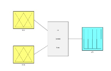
Fig.4..Rules of fuzzy logic controller
this fuzzy controller has two errors one is (E) Error another
one is (CE) Counter Error both are called input layer these are connected to hidden layer it means both inputs are compared as following rules[7],[16]
If (E is Negative) and (CE is Negative) then (u is Min) If (E is Negative) and (CE is Positive) then (u is Zero)
If (E is Positive) and (CE is Negative) then (u is Zero) If (E is Positive) and (CE is Positive) then (u is Max)
U id the output of fuzzy controller it is giving the pulses to pwm unit, this fuzzy controller is based on the input errors [15].
IJSER © 2015 http://www.ijser.org
International Journal of Scientific & Engineering Research, Volume 6, Issue 4, April-2015 92
ISSN 2229-5518
A basic variant of the PSO algorithm works by having a popu- lation (called a swarm) of candidate solutions (called parti- cles). These particles are moved around in the search-space according to a few simple formulae [1]. The movements of the particles are guided by their own best known position in the search-space as well as the entire swarm's best known posi- tion. When improved positions are being discovered these will then come to guide the movements of the swarm. The process is repeated and by doing so it is hoped, but not guaranteed, that a satisfactory solution will eventually be discovered [13].
n = 3; %No. of iterations. = n^3
kp1=1;
ki1=1;
simopt simset('solver','ode23t','SrcWorkspace','Current','DstWorkspac [tout,xout,current_fitness] = sim('Inverter_5',[0 0.5],simopt); local_best_fitness = current_fitness;
for i=1:n
for j=1:n kp1=i/1000; ki1=j/10;
if current_fitness(975,:) < local_best_fitness(975,:) %local best fitness
local_best_fitness = current_fitness;
kp_best = i/1000;
ki_best = j/10;
end
[global_best_fitness] = min(local_best_fitness(970:980,:);
end
end
N represents the number of iterations , n=3 it means 3*3 plane
is taken, total 9 times system is running and get the best val-
ue[9],[10],[11],[12],[13]. In this PSO method we use the PI con-
troller so we fix the kp and ki values, means initiation the val-
ues of kp and ki. Simopt means simulation optimization it has the simulation set in this simulation set has different types of commands, Src Workspace - Where to evaluate expressions [{base} | current | parent] This property specifies the work- space in which to evaluate MATLAB expressions defined In the model. The default is the base workspace.
Where to assign variables [base|{current}|parent] This prop- erty specifies the workspace in which to assign any variables defined in the model. The default is the current workspace. tout, xout means save time and save state.
Local best fitness=current fitness it means local best value is
consider as present best value. i, j are variables these are use to variable names in mat-lab. i=1:n , j=1:n these statement repre- sents the i and j values are 1 to n, n means number of itera- tions.
if current_fitness(975,:)<local_best_fitness (975), lo-
cal_best_fitness = current_fitness; these statements are if state- ments the standard comparison can be made. After this compres- sion variables find the kp best and ki best values. These values are equal to global best values.
Start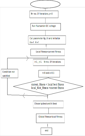
Fig5. Flow chart of PSO method
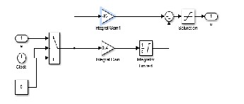
Fig6.Simulation diagram of PI controller![]()
IJSER © 2015 http://www.ijser.org
International Journal of Scientific & Engineering Research, Volume 6, Issue 4, April-2015 93
voltage reaches the constant magnitude of 415v.
Fig.7. Space vector pulse width modulation simulation diagram
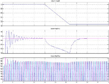
Fig.8:Simulation results of 3level inverter using PI controller .(a) Input fluctuated DC voltage, (b)Inverter output voltage(Vrms) (c) The output voltage(Vavg)
From fig 8.(a) The constant input DC voltage is applied from
0sec. to 0.4sec(i.e 20% more than the rated value). Then the
time scale from 0.4sec. to 0.5sec.the input DC voltage is de- creased from704.29V to 586v. Then time scale from 0.5sec. to
0.62sec. The DC voltage is gradually decreases from586v to
469.49V. Then after the input DC voltage magnitude is re-
mains constant from 0.62sec. to 1sec (i.e20% lesser than the
rated value).
From fig8.(b) it shows the output (Vrms) voltage from 0sec. to
0.4sec. the DC voltage magnitude is constant, voltage (Vrms) is
oscillated nature settled up to 0.3sec, then from 0.4sec.to
0.5sec.DC voltage is gradually decreases but output voltage
(Vrms) fluctuated from 415v to 411v. Then after input DC voltage
is decreased from 0.5sec. to 0.62sec. the voltage (Vrms) is also
decreased up to 408V. Then from the time scale 0.62sec. To 1sec,
input DC voltage is remains constant 469.49v and output (Vrms)
From fig.8(c) we observe that 0sec. to 0.4sec. Input DC is con- stant output voltage is maintain constant magnitude. From
0.4sec. to 0.62sec. The input DC voltage is decreases. in this case the output voltage magnitude is small decreased. Than after time scale from 0.62sec. to 0.8sec.the output voltage has increased to meet the rated value of magnitude. After 0.62sec. to 1sec. DC voltage is 20% lesser than the applied voltage magnitude even through this period output voltage magni- tude is reached the rated voltage and remains constant volt- age magnitude.
Using SVPWM method helps to improve the output voltage mag- nitude to maintain rated voltage with fast switching cycles.
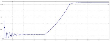
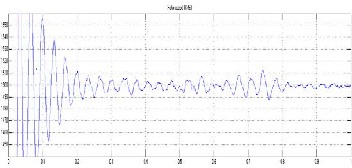
Fig9. PI controller error signal
Fig10.Rotor speed of induction motor (rpm)
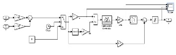
Fig11.Simulation diagram of Fuzzy controller
IJSER © 2015 http://www.ijser.org

International Journal of Scientific & Engineering Research, Volume 6, Issue 4, April-2015 94

system of Fuzzy logic simulation block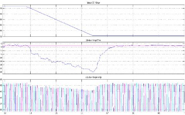
Fig15.Fuzy controller error signal
Fig12. Sub
From fig13.We can observe that the time scale 0sec. to 0.1sec. Input DC voltage is 716v fixed (i.e 22% more than the rated value) and RMS voltage get the small fluctuations shown in fig 13(b). And load voltage is 580v. From 0.1sec. To 0.36sec. the DC voltage is decreases from 716v to 457.78v (i.e 22% of fluctuation and RMS voltage is decreases from 415v to 400.8v and load voltage is decreases to 565v voltage magnitude as shown in fig13(c). In the scale from 0.36sec. to 1sec. DC voltage is maintain constant voltage magnitude of 457.78v(i.e 22% lesser than the rated value) and RMS voltage is increases to upto 415v and maintain constant voltage magnitude and load voltage also increases to 585v and maintain constant voltage magnitude accordingly as shown in fig13(a),(b)and(c).
The fig13 shows (a) input DC voltage,(b) Inverter output voltage(Vmrs) (c) the output voltage(Vavg) with fuzzy controller ha been reaches the constant RMS voltage within very less time with THD of 0.22%, as shown in fig13 and fig14.
Figure13.Simulation results of 3level inverter using Fuzzy con- troller with 22% DC voltage fluctuation
.(a) input DC voltage,(b) Inverter output voltage(Vrms) (c)
the output voltage(Vavg)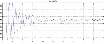
Fig14. Simulation results of dynamic load rotor speed using fuzzy-control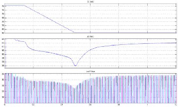
Figure16. Simulation results of 3level inverter using PSO- con- troller with 31% of DC voltage fluctuation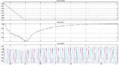
(a) input DC voltage,(b) Inverter output voltage(Vrms) (c) the output voltage(Vavg)
Fig 17. Simulation results of multilevel inverter using PSO- controller with zoom scale of fig16.
IJSER © 2015 http://www.ijser.org
International Journal of Scientific & Engineering Research, Volume 6, Issue 4, April-2015 95
ISSN 2229-5518
Fig18.Simulation results of dynamic load rotor speed using
PSO-controller.
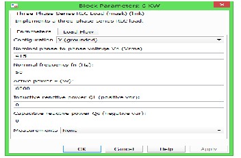
Fig.20. Three phase Static Load parameters
From fig10, 14, and 18 Simulation results of dynamic load ro- tor speed using PI, Fuzzy and PSO-controllers corresponding- ly shown, from this analysis the PI & Fuzzy controller results have the fluctuating speed behaviors. By using PSO controller motor speed is very smoothly controlling in case of DC volt- age fluctuating cases. From Table1 we can validate the effec- tiveness of controllers.
From fig 22. Indicate the Total Harmonic Distortion of the
voltage wave forms after reach the rated value by implement-
ing the control techniques.
Fig19. PSO- controller error signal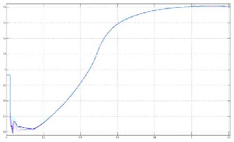
Time(sec)
From fig16. We can observe that time scale 0sec. to 0.1sec. In- put DC voltage is 768.82v fixed (i.e 31% is more than the rated value) and RMS voltage have constant magnitude and load voltage is 575v. From 0.1sec to 0.5sec, the DC voltage has the smooth decreeing from 768.82v to 404.96v (i.e 31% of fluctua- tion of DC magnitude) and RMS voltage is decreases from
415v to 382.7v and load voltage is also decreases to 529v volt- age magnitude, in the time scale from 0.5sec to 1.2sec. Input DC voltage is maintain constant voltage magnitude of 404.96v (i.e 31% less magnitude of initial value) and instantly RMS voltage is increases to 415v with smoothly and maintain con- stant voltage magnitude and load voltage also increases to rated value and maintain constant voltage magnitude. By im- plementing PSO method with 5HP IM & Resistive- load is reaches the constant RMS voltage within less time with final output voltage wich containTHD of 0.71%.
Fig21. Three phase Dynamic Load parameters
Table1.Results comparison between PI, Fuzzy and PSO con- troller
IJSER © 2015 http://www.ijser.org
International Journal of Scientific & Engineering Research, Volume 6, Issue 4, April-2015 96
ISSN 2229-5518
Fig 22. Total Harmonic Distortion Analysis.
This paper has presented new control methods for output voltage of a three phase multilevel inverter considering the fluctuated DC voltage. The comparison of PI, FUZZY and PSO controllers, the PSO controller is effective than other control- lers, we confirmed that, the control and absorption of DC volt- age fluctuation of about 31%, this is 10% of voltage fluctuation absorption more than the PI and FUZZY controllers dynamic load response also very well in this control method. The dis- advantage of the PSO controller is time consuming more than PI and FUZZY controllers. The advantage of PI controller is less THD and advantage of FUZZY-controller is taking less number of cycles to reach the rated value after the voltage dis- turbance and fast controlling. In these paper we conclude that the PSO-control technique is an effective one considering DC voltage fluctuation cases.
Future work will focus on further reduction of output volt- age distortion. For improving the voltage utilization factor
[1]H. Taghizadeh and M. Tarafdar Hagh,, “Harmonic Elimina- tion of Cascade Multilevel Inverters with Nonequal DC Sources Using Particle Swarm Optimization IEEE Transactios On Industrial Electronics, Vol.57, No11, November 2010 pp.
3678–3684.
[2]S.Hasan Saeed, “Automatic Control Systems” book Pub-
lished by S.k. Kataria and Sons, pp.450–471.
[3] Hamid Reza Mohammadi, Ali Akhavan “A New Adaptive
Selective Harmonic Elimination Method for Cascaded Multi-
level Inverters Using Evolutionary Methods” IEEE 23rd inter- national symposium on Industrial Electronics (ISIE)2014,pp:1484- 1489.
[4]Bouafia,A. ; Gaubert,J.-P. ; Chaoui,A.
![]()
“High performance direct power control of three-![]()
phase PWMboost rectifier under different supply voltage conditio
ns” 15th European Conference on
Power Electronics and Applications (EPE), 2013, pp: 1 – 8
[5] P. A. Janakiraman, and S. Abdul Rahman “Linear Pulse width Modulation Under Fluctuating Power Supply” IEEE Transactions On Industrial Electronics, Vol.61, NO. 4, April
2014,pp 1769- 1773
[6] Jin-Woo Jung, Nga Thi-Thuy Vu, Dong Quang Dang, Ton
Duc Do, Young-Sik Choi, and Han Ho Choi, “A Three-Phase
Inverter for a Standalone Distributed Generation System: Adaptive Voltage Control Design and Stability Analysis” IEEE Transactions On Energy Conversion, Vol. 29, No. 1, March
2014,pp: 46- 56
[7] Bayat, Z. ; Babaei, E. ; Badamchizadeh, M. “Low Order
Harmonics Elimination in MultilevelInverters Using Fuzzy
Logic Controller Considering the Variations of DC Voltage
Sources” International Conference on Electrical Machines and
Systems (ICEMS), 2011, pp: 1 – 6
[8] Edited by Dr. Valery D. Yurkevich “Advances in PID Con-
trol” book Publisher InTech,2011.
[9] Said El Beid, and Said Doubabi “DSP-Based Implementa-
tion of Fuzzy Output Tracking Control for a Boost Converter” IEEE Transactions On Industrial Electronics, Vol. 61, No. 1, January 2014,pp: 196-209.
[10] Lin Chengwu,Zhang xiaomin, Jiang Qiguang “Research on SVPWM inverter output control technology” Fifth Confer- ence on Measuring Technology and Mechatronics Automa- tion-2013,pp: 927-929
[11] Filho, F. ; Maia, H.Z. ; Mateus, T.H.A. ; Ozpineci, B. ; Tolbert,L.M.; Pinto,J.O.P.
“Adaptive Selective Harmonic Minimization Based on ANNs for Cascade Multilevel Inverters With Varying DC Sources” IEEE Transactions On Industrial Electronics Vol. 60, No. 5,
May 2013,pp: 1955-1962
[12] Panda, S.K. ; Kollimalla, S.K. ; Mishra, M.K. “Modified boost inverter topology for compensation ofun balanced and nonlinear loads in three phase system” Third International Conference on Sustainable Energy Technologies (ICSET), 2012 ,pp: 346 – 351
[13] A. K. Al-Othman, and Tamer H. Abdelhamid “Elimina-
tion of Harmonics in Multilevel Inverters with Non-Equal DC
Sources Using PSO” Conference on Power Electronics and
Motion Control EPE-PEMC.2008.pp: 606 – 613.
[14] Biji Jacob, and M. R. Baiju, “A New Space Vector Modulation Scheme for Multilevel Inverters Which Directly Vector Quantize the Reference Space Vector” IEEE Transactions On Industrial Electronics, Vol. 62, No. 1, pp:88-95, January 2015.
[15]Azuki Abdul Salam1, Nik Azran Ab Hadi “Fuzzy Logic Con- troller for Shunt Active Power Filter” 4th International Confer- ence on Engineering Technology and Technopreneuship (ICE2T), pp.no256-259,2014
[16] N.Madhanakkumar, T. S. Sivakumaran and D.Divya sri “Performance Analysis of PI and Fuzzy Control for Resonant Converter Incorporating Boost” International Conference on Sci- ence, Engineering and Management Research (ICSEMR 2014).
[17] Yao Zhezhi, Yi Lingzhi, Peng Hanmei, Fu Xi, Deng Dong
“Study of Simplified SVPWM Algorithm Based on Three-
Level Inverter” IEEE 6th Internationl Conference on Power
Electronics and Motion Control, IPEMC-2009 pp: 876 – 881.
IJSER © 2015 http://www.ijser.org
International Journal of Scientific & Engineering Research, Volume 6, Issue 4, April-2015 97
ISSN 2229-5518
[18]Amei, K.; Tanizaki, Y.; Ohji, T.; Sakui, M. “A Control Method of Superposition Ratio in the Improvement of Voltage Utilization Factor in Three phase MultilevelInverter con- sidering the DC Voltage Fluctuation” Power Conversion Confer- ence - Nagoya, 2007.7Publication Year: 2007 , Page(s):37 – 142
[19] Sreeja C, and Arun S “A Novel Control Algorithm for Three Phase Multilevel Inverter using SVM” IEEE PES Innova- tive Smart Grid Technologies India, 2011 pp: 262 - 267
[20] Lopez, O. ; Alvarez, J. ; Doval-Gandoy, J. ; Freijedo, F.D. “Multilevel Multiphase Space Vector PWM Algorithm “ IEEE Transactions On Industrial Electronics, Vol. 55, No. 5, May
2008.pp: 1933 – 1942.
IJSER © 2015 http://www.ijser.org