International Journal of Scientific & Engineering Research, Volume 4, Issue 8, August-2013 925
ISSN 2229-5518
Acceleration to LMS based STBC MC-CDMA Receiver
Muhammad Adnan Khan, Muhammad Umair, Muhammad Aamer Saleem Choudhry
Abstract— High data rate is one of the key demands of future networks like 4th generation (4G) networks. One of the key solutions is the systems like Multi-Carrier Code Division Multiple Access (MC-CDMA) or Orthogonal Frequency Division Multiplexing (OFDM). We have used Alamouti’s space time coding with MC-CDMA system in this paper. We proposed different types of Least Mean Square (LMS) algorithm to measure the performance of sub-optimum MC-CDMA receiver with exceptional relationship. We find out that sign-sign LMS with proposed relation has the fastest convergence rate than the other types of LMS receiver.
Index Terms— Sub optimal systems, STBC, MC-CDMA, LMS Algorithm, Convergence rate.
—————————— ——————————
ata transmission is increasing hugely now a days in net- works like IEEE 16m and 4th generation (4G) technolo- gies. This demand cannot be fulfilled by single carrier
systems like code-division multiple access (CDMA) systems. They have some critical problems such as the difficulty of syn- chronization, severe inter-chip and inter-symbol interferences due to the multipath fading channels.
Some of the solutions to fulfill high data demand are or- thogonal frequency-division multiplexing (OFDM), multi- carrier CDMA (MC-CDMA) and multicarrier direct-sequence (MC-DS)-CDMA. They are considered as a potential candidate for the next-generation high data rate wireless systems [1].
In this paper, we adopted MC-CDMA system. The MC- CDMA system is a blend of frequency-domain spreading and OFDM. An available bandwidth is decomposed into a set of disjoint equal bandwidth of small size. Each sub-band signal practiced only frequency-flat fading channel. So MC-CDMA systems are tougher to the distortion induced by time- dispersive channels than single carrier CDMA systems
In [2] , it is shown that maximum diversity gain is achieved
through Alaumouti space time block codes (STBC). They are
being used for attaining transmit diversity gain in the third
generation communication standards [3], [4]. The two consec-
utive symbols are simultaneously transmitted using two
transmit antennas at the first symbol interval in Alamouti’s
STBC. Their conjugated symbols with or without sign change
are transmitted at the next symbol interval. We have used two
received antenna for fast convergence rate in space-time block
codes.
The multiuser receivers are categorized as: optimal receiv-
ers and suboptimal receivers. The optimal receivers are not
realistic due to too much complexity. However, the suboptimal
receivers have been attracted due to low complexity. One of
them is minimum mean-squared error (MMSE) receiver in
which filter coefficients are designed to minimize the MSE.
Batch-processed multiuser receivers for DS-CDMA or MC-
CDMA systems employing STBC have been proposed in [5],
[6], and [7]. In general, the batch-processed receivers require
the estimation of the inverse autocorrelation matrix of the ex-
tended received signal.
In this paper, we proposed different variations of LMS al-
gorithm to STBC based MC-CDMA receiver by imposing a relationship on it.
The paper is organized as follows. Section 2 describes pro- posed system model and the proposed modified LMS adap- tive sub-optimum receiver is given in Section 3. MMSE based accelerated receiver cost function is given in section 4. Pro- posed LMS sub-optimum adaptive receiver is in section 5. Simulation results are given in Section 6 Finally, Section 7 con- cludes the paper.
We used Alamouti’s STBC code in MC-CDMA system. We considered two antennas on each of transmitter and receiver side.
Fig.1.Transmitter structure for MC-CDMA system employing STBC
The fig 1 shows the MC-CDMA transmitter structure. We assume that we have two transmit antennas x and y respec-
tively. The symbols 𝑡𝑚 (2i − 1) and
𝑡𝑚 (2i) are sent through antenna x and y on the first symbol
∗ ∗
interval. The two consecutive symbols −𝑡𝑚 (2𝑖)and 𝑡𝑚 (2i-1)
are sent through antenna x and y respectively on the next
symbol interval. We used the spreading code pair
(𝑐𝑚,1 , 𝑐𝑚,2 ) of size M ×1 for frequency domain spreading from the antenna x and y respectively, where 𝑐𝑚,𝑢 is given
by
IJSER © 2013 http://www.ijser.org
International Journal of Scientific & Engineering Research, Volume 4, Issue 8, August-2013 926
ISSN 2229-5518
𝐜m,u = �cm,u,1 , cm,u,2 , … … . , cm,u,M � t (1)
Then, an M-point IFFT operation is performed on spread-
na u of user m by 𝒅𝑚,𝑢 , than obtained signal vector can be written
as
ing data, where M is the number of subcarriers. It is assumed that the number of subcarriers and processing gain of the spreading code are equal. The IFFT output signal is parallel- to-serial converted. The cyclic prefix are inserted to reduce
M
𝐫(2𝑖 − 1) = � �𝐝𝑚,1 𝐭𝑚 (2𝑖 − 1) + 𝐝𝑚,2 𝐭𝑚 (2𝑖)� + 𝐮(2𝑖 − 1)
m=1
M
∗ (2𝑖) + 𝐝
𝐭∗ (2𝑖 − 1)� + 𝐮(2𝑖) (5)
inter-symbol interference (ISI) and inter-carrier interference
(ICI) then transmitted through the channel. We used Additive white Gaussian noise (AWGN) and the rayliegh fading chan-
𝐫(2𝑖) = � �−𝐝𝑚,1 𝐭𝑚
m=1
𝑚,2 𝑚
nel with maximum tape delay equal to spreading gain.
Defining the extended received signal vector for the two consecutive symbols by y(i) yields [8]
𝒚(𝑖) = [𝐫 𝑇 (2𝑖 − 1) 𝐫 𝐻 (2𝑖)]𝑇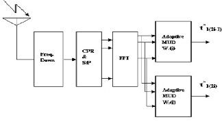
= ∑𝑀
�𝐟𝑚,1 𝐭𝑚 (2𝑖 − 1) + 𝐟𝑚,2 𝐭𝑚 (2𝑖)� + 𝐯(𝑖) (6)
𝑚=1
Where 𝐟𝑚,𝑛 and 𝐯(𝑖) are given by
𝐟𝑚,1 = �
𝐝𝑚,1
∗
� , 𝐟𝑚,2 = �
𝐝𝑚,2
�, 𝐯(𝑖) = �
𝐮(2𝑖 − 1)
� (7)
𝐝𝑚,1
−𝐝𝑚,1
𝐮(2𝑖)
Fig.2. Receiver structure for MC-CDMA system employing STBC
The fig 2 shows the receiver structure of MC-CDMA sys-
We assume that our desired user is 1. Defining 𝐏1 =
�𝐟𝟏,𝟏 𝐟𝟏,𝟐 � and𝐭1 = [t1 (2𝑖 − 1) 𝐭1 (2𝑖)] 𝑇 . The extended received
signal vector y(i) in (6) can be rewritten as
𝐲(𝑖) = 𝐏1 𝐭1(i) + 𝒛(𝑖) (8)
Where 𝐳(𝑖) is additive white Gaussian noise given by
tem. The cyclic prefix from the received signal is removed ini-
𝐳(i) = ∑𝑀
�𝐟𝑚,1 𝐭𝑚 (2𝑖 − 1) + 𝐟𝑚,2 𝐭𝑚 (2𝑖)� + 𝐯(i) (9)
tially. The resulting signal is serial-to-parallel converted which observes M-point FFT operation. The frequency domain re- ceived signal with assumption that the maximum delay spread is less than the cyclic prefix length for all users is given by
𝑚=2
If we define the filter weight vectors 𝐰1 and 𝐰2with size
2𝑀 × 1 for distinguishing 𝑡𝑚 (2i − 1) and
𝑡𝑚 (2i) respectively, then minimum mean-squared error
(MMSE) at the filter output is given by
𝐫(2𝑖 − 1) = ∑M
�𝐒𝑚,1 𝐜𝑚,1 𝐭𝑚 (2𝑖 − 1) + 𝐒𝑚,2 𝐜𝑚,2 𝐭𝑚 (2𝑖)� +
𝑚=1
M ∗
𝐮(2𝑖 − 1) (3)
∗
𝐃(𝐰𝟏, 𝐰𝟐 ) = E[|𝐖 𝐻 𝐲(𝑖) − 𝐭1 (𝑖)| 2]
𝐻 2
𝐫(2𝑖) = ∑𝑚=1�−𝐒𝑚,1 𝐜𝑚,1 𝐭𝑚 (2𝑖) + 𝐒𝑚,2 𝐜𝑚,2 𝐭𝑚 (2𝑖 − 1)� +
= E[|𝐰1 𝐲(𝑖) − 𝐭1 (2𝑖 − 1)| ] +
𝐻 𝐲(𝑖) − 𝐭 (2𝑖)| 2]
𝐮(2𝑖) (2)
Where 𝐒𝑚,𝑢 is the frequency-domain channel response of user
m from the transmit antenna u given by
Sm,u = diag�𝑆𝑚,𝑢,0 , 𝑆𝑚,𝑢,1 , 𝑆𝑚,𝑢,2 , … … … . , 𝑆𝑚,𝑢,𝑀−1 � (4) and 𝐮(𝑖) is the complex additive white Gaussian noise (AWGN) with covariance matrix 𝜎2 𝐈 i.e; 𝐈 is an identity matrix of size 2𝑀 × 2𝑀, and zero mean. The mth user uth infor- mation data is 𝑡𝑚 (𝑢) is an identically distributed random vari-
[|𝐰2 1
= 𝐃1 (𝐰1)+ 𝐃𝟐 (𝐰𝟐 ) (10)
The minimization problem in [4] is required in order to at-
tain the Minimum Mean Square Error (MMSE) receiver for the
above mentioned STBC based MC-CDMA system:
�𝐰𝑜,1, 𝐰𝑜,2 � = 𝑎𝑎𝑎 m�in 𝐃(𝐰1 , 𝐰2 )
𝐰1 ,𝐰2
= {m�in 𝐃1 (𝐰1 )+m�in 𝐃𝟐 (𝐰𝟐 ) (11)
able with unit variance and zero mean.
We define the effective spreading code at the transmit anten-
𝐰1
𝐰2
————————————————
The MMSE receiver works by setting the derivatives of
these filter weight 𝐰1and 𝐰𝟐 to zero which is
• Muhammad Adnan Khan is currently pursuing PhD degree program in
−1 𝐝
, 𝐰
= 𝐑−1 𝐝
(12)
𝐰𝑜,1 = 𝐑 𝑦
1,1
𝑜,2
𝑦 1,2
electronic engineering in ISRA University, Pakistan, PH-
00923327262791. E-mail: adnan_600@yahoo.com
• Muhammad Umair is currently pursuing PhD degree program in electron- ic engineering in ISRA University, Pakistan, PH-00923006806097. E-
Where 𝐑𝑦 = 𝐸[𝐫(𝑘)𝐫𝐻 (𝑘)] which is the autocorrelation matrix of 𝐫(𝑘). The MMSE with respect to (12) is
𝐷𝑚𝑖𝑛 = 𝐃�𝐰𝑜,1, 𝐰𝑜,2 �
mail: umairbwp@gmail.com
𝐻 −1
𝐻 −1
= �1 − 𝐝1,1 𝐑𝑦 𝐝1,1� + �1 − 𝐝1,2 𝐑𝑦 𝐝1,2 � (13)
IJSER © 2013
International Journal of Scientific & Engineering Research, Volume 4, Issue 8, August-2013 927
ISSN 2229-5518
The unique association between the optimum weights
𝐰𝑜,1 and 𝐰𝑜,2 is described in this part as in (17). Suppose 𝐑y by its sub matrices of dimensions 𝑀 × 𝑀.
𝐑1 𝐑 2
where the sign function is applied to t(n) on element by element basis.
The Sign-Sign algorithm is given by
w(n + 1) = w(n) + 2μ sign�ℯ(n)�sign�t(n)� (22)
𝐑 y = �𝐑
𝐑 4
� (16)
where the sign function is applied to ℯ(n) and t(n) on element by
It was noted that 𝐑y has a certain relationship in its diag- onals. The relationship is 𝐑4 = 𝐑 ∗ 1 and 𝐑3 = −𝐑 ∗ 2.
This association between MMSE filter weight vectors is used
in (13) to derive a special relationship. The optimal weight
vectors 𝐰𝑜,1 and 𝐰𝑜,2 of dimension 𝑀 ×1are presented as
element basis.
We supposed a STBC based MC-CDMA system. The
𝐰1,1
𝐰o,1 = �
1,2
�, 𝐰 = �𝐰2,3� (17)
1,4
number of sub carriers is N=32 equivalent to length of the
spreading sequence. The complex random spreading sequence
and the following relation is satisfied by these vectors as in [9]:
𝐰1,2 = 𝐰 ∗ 2,3 , 𝐰1,4 = −𝐰 ∗ 1,1 (18)
The MMSE filter weight vectors are given in (17) satisfies
the relation given in (18). So it’s a very good sign in order to increase the convergence rate by only updating the weight vectors satisfying the relationship in (18). The cost function of MMSE in (10) can be reformed as only func-
tion of 𝐰𝑑 R and 𝐰𝑒 :
D𝑁 = D𝑁1 (𝐰𝑑 , 𝐰𝑒 ) + D𝑁2 (𝐰𝑑 , 𝐰𝑒 ) (19)
where
is used for each user. The values of its real and imaginary![]()
![]()
parts are independently and randomly taken as 1/√2 and -
1/√2 with equal probability. The Rayleigh multipath fading
channels with three paths is used for each user. The fading
gains are generated by using a complex Gaussian distribution, which are normalized such that the average energy of the channel is unity. The spreading sequences and channel coeffi- cients are fixed over all simulation cycles.
The fig. 3 shows MMSE learning curves for proposed signed LMS and conventional LMS. The number of users is
𝐻 𝑇 ∗ 2
D𝑁1 (𝐰𝑑 , 𝐰𝑒 ) = 𝐸[𝐰𝑑 𝑎(2𝑖 − 1) + 𝐰e 𝑎 (2𝑖) − 𝑑1 (2𝑖 − 1)| ]
and
M=20 and signal to noise ratio (SNR) is 25dB. The Number of
symbols for proposed signed LMS algorithm without relation
𝐻 𝑇 ∗ 2
D𝑁2 (𝐰𝑑 , 𝐰𝑒 ) = 𝐸[|𝐰e 𝑎(2𝑖 − 1) + 𝐰𝑑 𝑎 (2𝑖) − 𝑑1 (2𝑖)| ]
We have proposed modified LMS algorithm in this paper. These algorithms were designed to be adaptive in order to improve the performance of sub-optimum receiver in terms of better convergence rate, reduce computational complexity and decrease the steady state- error mean-square error. These algo- rithms are signed, signed -regressor and signed-signed.
We have proposed modified LMS algorithm in this paper. The signed LMS algorithm is defined by following relation- ship:
w(n + 1) = w(n) + 2µ sign�ℯ(n)�t(n) (20)
where
is 340 and number of symbols for conventional LMS algorithm
without relation is 350. The number of symbols for proposed
signed LMS algorithm with relationship is 250. The number
symbols for conventional LMS algorithm with relationship is
260. This result shows that convergence rate of proposed
signed LMS algorithm and conventional LMS algorithm with
relation is faster than signed LMS and conventional LMS
without relation.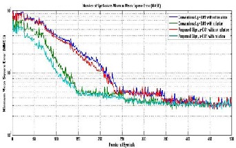
Fig.3. MMSE learning curves for proposed signed LMS algorithm and
1 𝑛 > 0
𝑠𝑖𝑎𝑛(𝑛) = � 0 𝑛 = 0
−1 𝑛 < 0
is the signum function. By introducing the signum function
and setting 𝜇 to a value of power of two.
The signed regressor or data sign algorithm is given as fol- lows
w(n + 1) = w(n) + 2µ ℯ(n)sign�t(n)� (21)
conventional LMS algorithm with and without relation
The fig. 4 shows MMSE learning curves with numbers of users are M=20 and signal to noise ratio (SNR) is 25dB. The number of symbols for proposed signed regressor algorithm without relationship is 330. The number of symbols for con- ventional LMS algorithm without relationship is 350. The number of symbols for proposed signed regressor algorithm
IJSER © 2013 http://www.ijser.org
International Journal of Scientific & Engineering Research, Volume 4, Issue 8, August-2013 928
ISSN 2229-5518
with relationship is 230. The number symbols for conventional LMS algorithm with relationship is 260. This result shows that convergence rate of proposed signed LMS algorithm and con- ventional LMS algorithm with relationship is faster than the schemes without relation.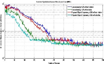
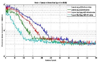
Fig.4. MMSE learning curves for proposed signed regressor algorithm and conventional LMS algorithm with relation and without relation
Fig.5. MMSE learning curves for proposed sign-sign algorithm and con- ventional LMS algorithm with and without relation
The fig. 5 shows MMSE learning curves with numbers of user are M=20 and signal to noise ratio (SNR) is 25dB. The Number of symbols for proposed sign-sign algorithm without relation to achieve the constant Bit Error Rate (BER) is 300. The number of symbols for conventional LMS algorithm without relation to achieve constant BER is 350. While, the number of symbols for proposed sign-sign algorithm with relation to achieve the constant BER is 200. The number symbols for con- ventional LMS algorithm with relationship to achieve the con- stant BER is 250. This result shows that convergence rate of proposed signed LMS algorithm and conventional LMS algo- rithm with relation is faster than without relation.
The fig. 6 shows MMSE learning curves for proposed LMS
algorithms without relationship. The numbers of user are M=20 and signal to noise ratio (SNR) is 25dB. The Number of symbols to achieve constant bit error rate for conventional LMS, signed LMS, signed regressor LMS and sign-sign LMS algorithm without relationship are 350, 340, 330 and 300. This
result shows that convergence rate of proposed sign-sign LMS
algorithm is faster than the other LMS based schemes.
Fig.6. Comparison of MMSE learning curves for proposed LMS algo- rithm without relation
The fig. 7 shows MMSE learning curves for proposed LMS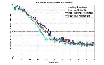
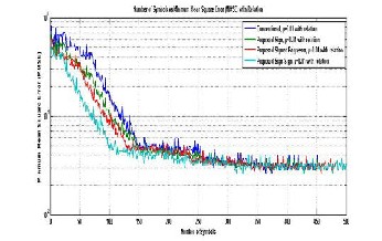
algorithms with relation. The numbers of user are M=20 and signal to noise ratio (SNR) is 25dB. The Number of symbols to achieve constant bit error rate for conventional LMS, signed LMS, signed regressor LMS and sign-sign LMS algorithm without relationship are 260, 250, 230 and 200. This result shows that convergence rate of proposed sign-sign LMS algo- rithm with relation is faster than the other LMS based schemes.
Fig.7. Comparison of MMSE learning curves for proposed LMS algorithm with relation
In this paper, we use different LMS based algorithms to meas- ure the performance of sub-optimum MC-CDMA receiver by imposing a relationship on it. These three different LMS fla- vors are signed, signed-regressor and sign-sign LMS. It is not- ed that convergence rate of all these three flavors is faster than conventional LMS. It is noted that sign-sign LMS with relation has low computation complexity and faster convergence rate than all other flavors of LMS.
IJSER © 2013 http://www.ijser.org
International Journal of Scientific & Engineering Research, Volume 4, Issue 8, August-2013 929
ISSN 2229-5518
[1] S. Hara and R. Prasad , "Overview of multicarrier CDMA," IEEE Com-mun. Mag. , Vol. 35, pp . I 26-33 ,Oec. 1997 . Xilinx, “Design Reuse Methodology for ASIC and FPGA Designers”, 2004. www.xilinx.com.
[2] S. Alamouti, "A simple transmit diversity technique for wireless com-muni cations," IEEE 1. Select. Areas Commun. , Vol. 16, pp.
1451-1458.
[3] 3GPP Technical Specification 36.211 V8 .6.0," Evolved universal
terrestrial radio access: Physical channels and modulation," Mar .
2009.
[4] S. Verdu , Multiuser Detection , Cambridge, U. K. : Cambridge
Univ. Press ,1998 .
[5] Z . Li and M. Lat va-aho, "Nonblind and semi bind space-time frequency multiuser detection for space-time block coded MC- COMA," IEEE Trans.Wireless Commun. , Vol. 4, pp . 1311-1318, Ju- ly , 2005 .
[6] 1. L. Yu and I.-T. Lee , " MIMO capon receiver and channel estima- tion for space-time coded COMA systems," IEEE Trans. Wireless Commun ., Vol.5, pp. 302 3-3028, Nov . 2006.
[7] H. Li, X. Lu, and G . B. Giannakis, "Capon multiuser receiver for CDMA systems with space-time coding," IEEE Trans. Signal Pro- cessing, Vol. 50 ,pp .1193-1204,May,2002.
[8] Bangwon Seo and Jae Young Ahn, “LMS Adaptive Receiver for
Uplink Space-Time Coded MC-CDMA System”, ISBN 978-89-5519-
146-2, Feb. 7-10, 2010 ICACT 2010.
[9] Bangwon Seo, Woo-Geun, Cheol Jeong and Hyung-Myung Kim, “Fast Convergent LMS adaptive receiver for MC-CDMA system with Space-Time Block Coding”, IEEE Communication Letters, Vol.
14, No. 8, August 2010.
IJSER © 2013 http://www.ijser.org