International Journal of Scientific & Engineering Research Volume 2, Issue 5, May-2011 1
ISSN 2229-5518
A Few Aspects of Power Quality Improvement
Using Shunt Active Power Filter
C.Nalini Kiran, Subhransu Sekhar Dash, S.Prema Latha
Abstract- Power quality standards (IEEE-519) compel to limit the total harmonic distortion within the acceptable range .This paper mainly deals with shunt active power filter which has been widely used for harmonic elimination. Active power filter which has been used here monitors the load current constantly and continuously adapt to the changes in load harmonics. The performance of three phase shunt active power filter using instantaneous power theory with PI and Hysteresis current controller is explained in this paper.
Index Terms- Active power filters (APF), composite load, harmonic compensation, linear and non linear load, reactive power.
—————————— • ——————————
1 INTRODUCTION
harmonic is a component of a periodic wave having a frequency that is an integral multiple of the fundamental power line frequency. Harmonics are the multiple of the fundamental frequency, and whereas total harmonic distortion is the contribution of all the harmonic frequency currents to the fundamental. Harmonics are the by-products of modern electronics. They occur frequently when there are large numbers of personal computers (single phase loads), uninterruptible power supplies (UPSs), variable frequency drives (AC and DC) or any electronic device using solid state power switching supplies [1] to convert incoming AC to DC. Non-linear loads create harmonics by drawing current in abrupt short pulses, rather
than in a smooth sinusoidal manner.
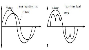
Fig: 1 Difference between Linear and Non-Linear Loads
The terms “linear” and “non-linear” define the relationship of current to the voltage waveform. A linear relationship exists between the voltage and current, which is typical of an across-the-line load. A non-linear load has a discontinuous current relationship that does not correspond to the applied voltage waveform. All variable frequency drives cause harmonics because of the nature of the frontend rectifier.
1.1 Need For Harmonic Compensation:
The implementation of Active Filters in this modern electronic age has become an increasingly essential element to the power network. With advancements in technology since the early eighties and significant trends of power electronic devices among consumers and industry, utilities are continually pressured in providing a quality and reliable supply. Power electronic devices [2] such as computers, printers, faxes, fluorescent lighting and most other office equipment all create harmonics. These types of devices are commonly classified collectively as ‘nonlinear loads’. Nonlinear loads create harmonics by drawing current in abrupt short pulses rather than in a smooth sinusoidal manner. The major issues associated with the supply of harmonics to nonlinear loads are severe overheating and insulation damage. Increased operating temperatures of generators and transformers degrade the insulation material of its windings. If this heating were continued to the point at which the insulation fails, a flashover may occur should it be combined with leakage current from its conductors. This would permanently damage the device and result in loss of generation causing widespread blackouts.
One solution to this foreseeable problem is to
install active filters for each nonlinear load in the power system network. Although presently very uneconomical, the installation of active filters proves indispensable for solving power quality [1][2] problems in distribution networks such as harmonic current compensation, reactive current compensation, voltage sag compensation, voltage flicker compensation and negative phase sequence current compensation. Ultimately, this would ensure a polluted free system with increased reliability and quality.
The objective of this project is to understand the
modeling and analysis of a shunt active power filter. In
IJSER © 2011 http://www.ijser.org
International Journal of Scientific & Engineering Research Volume 2, Issue 5, May-2011 2
ISSN 2229-5518
doing so, the accuracy of current compensation for current harmonics found at a nonlinear load, for the PQ theory control technique is supported and also substantiates the reliability and effectiveness of this model for integration into a power system network. The model is implemented across a two bus network including generation to the application of the nonlinear load.
The aim of the system simulation is to verify the
active filters effectiveness for a nonlinear load. In simulation, total harmonic distortion measurements are undertaken along with a variety of waveforms and the results are justified accordingly.
One of the most important features of the shunt
active filter system proposed is its versatility over a variety of different conditions. The application of the positive sequence voltage detector from within the active filter controller is the key component of the system. The positive sequence voltage detector gives incredible versatility to the application of the active filter, because it can be installed and compensate for load current harmonics even when the input voltage is highly distorted. When filters alike do not contain this feature and is installed with a distorted voltage input, the outcome is a low efficient current harmonic compensator with poor accuracy of compensation current determination.
1.2 Harmonic filters:
Harmonic filters are used to eliminate the harmonic distortion caused by nonlinear loads. Specifically, harmonic filters are designed to attenuate or in some filters eliminate the potentially dangerous effects of harmonic currents active within the power distribution system. Filters can be designed to trap these currents and, through the use of a series of capacitors, coils, and resistors, shunt them to ground. A filter may contain several of these elements, each designed to compensate a particular frequency or an array of frequencies.
1.3 Types of harmonic filters involved in harmonic
compensation:
Filters are often the most common solution that is used to mitigate harmonics from a power system. Unlike other solutions, filters offer a simpler inexpensive alternative with high benefits. There are three different types of filters each offering their own unique solution to reduce and eliminate harmonics. These harmonic filters are broadly classified into passive, active and hybrid structures. The choice of filter used is dependent upon the nature of the problem and the economic cost associated with implementation.
A passive filter is composed of only passive
elements such as inductors, capacitors and resistors thus not
requiring any operational amplifiers. Passive filters are inexpensive compared with most other mitigating devices. Its structure may be either of the series or parallel type. The structure chosen for implementation depends on the type of harmonic source present. Internally, they cause the harmonic current to resonate at its frequency. Through this approach, the harmonic currents are attenuated in the LC circuits tuned to the harmonic orders requiring filtering. This prevents the severe harmonic currents traveling upstream to the power source causing increased widespread problems.
An active filter is implemented when orders of
harmonic currents are varying. One case evident of demanding varying harmonics from the power system are variable speed drives. Its structure may be either of the series of parallel type. The structure chosen for implementation depends on the type of harmonic sources present in the power system and the effects that different filter solutions would cause to the overall system performance.
Active filters use active components such as IGBT- transistors to inject negative harmonics into the network effectively replacing a portion of the distorted current wave coming from the load.
This is achieved by producing harmonic
components of equal amplitude but opposite phase shift, which cancel the harmonic components of the non-linear loads. Hybrid filters combine an active filter and a passive filter. Its structure may be either of the series or parallel type. The passive filter carries out basic filtering (5th order, for example) and the active filter, through precise control, covers higher harmonics.
1.4 Passive Filters:
Passive filters are generally constructed from passive elements such as resistances, inductances, and capacitances. The values of the elements of the filter circuit are designed to produce the required impedance pattern. There are many types of passive filters, the most common ones are single-tuned filters and high-pass filters. This type of filter removes the harmonics by providing a very low impedance path to the ground for harmonic signals.
1.4.1 Advantages and Disadvantages of the Passive
Filters
The advantages of the Passive filters are:
• Shunt filters have the extra advantage of providing reactive compensation needed by the harmonic producing devices.
The disadvantages of the Passive filters are:
IJSER © 2011 http://www.ijser.org
International Journal of Scientific & Engineering Research Volume 2, Issue 5, May-2011 3
ISSN 2229-5518
• The source impedance influences the compensation characteristics of the LC filters.
• Frequency variation of the power system and
tolerances in filter components affect the compensation characteristics of the LC filters.
1.5 Representation of harmonics:
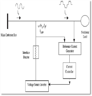
Fig: 2 Harmonics from a Non Linear Load
Fig 2 illustrates components of shunt connected active power filter with wave forms showing cancellation of harmonics from a non-linear load.
The current waveform for cancelling harmonics is achieved with the voltage source inverter and reactor. The reactor converts the voltage signal created by the inverter to a current signal. The desired waveform is obtained by accurately controlling the switches in the inverter. Control of the current wave shape is limited by the switching frequency of the inverter and by the available driving voltage across the interface reactor.
The driving voltage across the reactor determines the maximum di/dt that can be achieved by the filter. This is important because relatively high values of di/dt may be needed to cancel higher order harmonic components.
2 ACTIVE FILTERS
2.1 Introduction to Active Filters:
The increasing use of power electronics-based loads (adjustable speed drives, switch mode power
supplies,etc.) to improve system efficiency and controllability is increasing the concern for harmonic distortion levels in end use facilities and on the overall power system. The application of passive tuned filters creates new system resonances which dependent on specific system conditions. In addition, passive filters often need to be significantly overrated to account for possible harmonic absorption from the power system. Passive filter ratings must be co-coordinated with reactive power requirements of the loads and it is often difficult to design the filters to avoid leading power factor operation for some load conditions.
Active filters have the advantage of being able to compensate for harmonic without fundamental frequency reactive power concerns. This means that the rating of the active power can be less than a comparable passive filter for the same non-linear load and the active filter will not introduce system resonances that can move a harmonic problem from one frequency to another.
2.2 Types of Active Filters:
Active filter can be classified based on the connection scheme as:
• Shunt active filter
• Series active filter and
• Hybrid active filter.
2.2.1 Shunt Active Filter:
The active filter concept uses power electronic equipment to produce harmonic current components that cancel the harmonic current components that cancel the harmonic current components from the non- linear loads.. In this configuration, the filter is connected in parallel with the load being compensated
.Therefore the configuration is often referred to as an
active parallel or shunt filter.
Fig 3 illustrates the concept of the harmonic current cancellation so that the current being supplied from the source is sinusoidal. The voltage source inverter used in the active filter makes the harmonic control possible. This inverter uses dc capacitors as the supply and can switch at a high frequency to generate a signal that will cancel the harmonics from the non- linear load.
The active filter does not need to provide any real power to cancel harmonic currents from the load. The harmonic currents to be cancelled show up as
IJSER © 2011 http://www.ijser.org
International Journal of Scientific & Engineering Research Volume 2, Issue 5, May-2011 4
ISSN 2229-5518
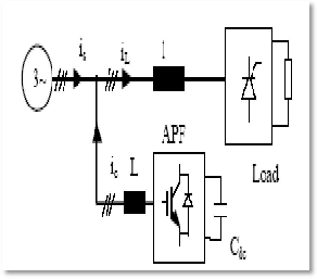
reactive power. Reduction in the harmonic voltage distortion occurs because the harmonic currents flowing through the source impedance are reduced. Therefore, the dc capacitors and the filter components must be rated based on the reactive power associated with the harmonics to be cancelled and on the actual current waveform (rms and peak current magnitude) that must be generated to achieve the cancellation.
Fig: 3 Shunt Active Power Filter
The current wave form for canceling harmonics is achieved with the voltage source inverter in the current controlled mode and an interfacing filter. The filter provides smoothing and isolation for high frequency components. The desired current waveform is obtained by accurately controlling the switching of the insulated gate bipolar transistors (IGBT’s) in the inverter. Control of the current wave shape is limited by the switching frequency of the inverter and by the available driving voltage across the interfacing inductance.
The driving voltage across the interfacing inductance determines the maximum di/dt that can be achieved by the filter. This is important because relatively high values of di/dt may be needed to cancel higher order harmonic components. Therefore, there is trade –off involved in sizing the interface inductor. A large inductor is better for isolation from the power system and protection from transient disturbances. However, the larger inductor limits the ability of the active filter to cancel higher order harmonics.
The inverter in the Shunt Active Power filter is a bilateral converter and it is controlled in the current Regulated mode i.e. the switching of the inverter is
done in such a way that it delivers a current which is equal to the set value of current in the current control loop. Thus the basic principle of Shunt Active Filter is that it generates a current equal and opposite to the harmonic current drawn by the load and injects it to the point of coupling there by forcing the source current to be pure sinusoidal. This type of Shunt Active Power Filter is called the Current Injection Type APF.
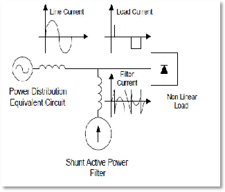
. Fig: 4 shows need of shunt active filter
2.3 Harmonic compensation:
2.3.1 Current Harmonic Compensation:
Current harmonic compensation strategies are exceptionally important .Current harmonics are greatly reduced by the compensation of voltage harmonics at the consumer’s point of common coupling. The reduction in current harmonics is not only important for reasons such as device heating and reduction in life of devices but also in design of power system equipment. One of the major design criteria covers the magnitude of the current and its waveform.
This is to reduce cable and feeder losses. Since the root mean square (RMS) of the load current incorporates the sum of squares of individual harmonics, true current harmonic compensation will aid system designers for better approached power rating equipment.
2.3.2 Harmonic detection and extraction:
A shunt active filter acts as a controllable harmonic current source. In principle, harmonic compensation is
IJSER © 2011 http://www.ijser.org
International Journal of Scientific & Engineering Research Volume 2, Issue 5, May-2011 5
ISSN 2229-5518
achieved when the current source is commanded to inject harmonic currents of the same magnitude but opposite phase to the load harmonic currents. Before the inverter can subtly inject opposing harmonic currents into the power system, appropriate harmonic detection strategies must be implemented to efficiently sense and determine the harmonic current from the nonlinear load.
2.4 Types of harmonic detection strategies:
There are 3 different types of harmonic detection strategies used to determine the current reference for the active filter. These are:
1. Measuring the load harmonic current to be
compensated and using this as a reference command.
2. Measuring source harmonic current and controlling the filter to minimize it.
3. Measuring harmonic voltage at the active filter point of common coupling (PCC) and controlling the filter to minimize the voltage distortion.
So out of these harmonic detection strategies here we are using first method i.e., measuring the load current.
2.5 SPECIFICATION OF THE DESIGN
2.5.1 PI Controller Gain value:
KP=0.32
KI=0.12
Filter inductance=0.01H Filter capacitance=1400µf
2.5.2 Active power filter:
Table 1: active power filter specifications
Dc link voltage | Vdc | 600V |
DC side capacitance | C | 10001F |
AC side inductance | Lc | 30mH |
AC side resistance | Rc | 10'0 |
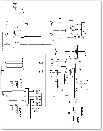
3 SHUNT ACTIVE POW ER FILTER
3.1) Introduction to Open Loop System:
In typical distribution systems the proliferation of diode rectifiers has resulted in serious utility interface issues as well as power quality degradation such as supply current and voltage harmonics, reactive power, flicker and resonance problems in industrial applications. Voltage distortion due to current harmonics is becoming a major problem for the utilities at distribution levels.
Utilities more frequently encounter harmonic related problems, such as higher transformer and line losses, reactive power and resonance problems, required derating of distribution equipment, harmonic interactions between customers or between the utility and load, reduced system stability and reduced safe operating margins. This has led to the proposal of more stringent requirements regarding power quality; standards such as IEEE-519 [5] reflect these preoccupations.
Passive filters are being used widely for harmonic elimination. However, they may create system resonances, need to be significantly overrated to account for possible harmonic absorption from the power system, must be coordinated with reactive power requirements of the loads and need a separate filter for each harmonic frequency to be cancelled. The concept of using active power filters to mitigate harmonic problems and to compensate reactive power was proposed more than two decades ago. Since then the theories and applications of active power filters have become more popular and have attracted great attention. The concept of using active power filters to mitigate harmonic problems and to compensate reactive power was proposed more than two decades ago.
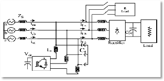
Fig:5 Main block diagram of an open loop system
. Without the drawbacks of passive harmonic filters, the active power filter appears to be a viable solution for reactive power compensation as well as for eliminating
harmonic currents.
IJSER © 2011 http://www.ijser.org
International Journal of Scientific & Engineering Research Volume 2, Issue 5, May-2011 6
ISSN 2229-5518
The schematic diagram of a power conditioner system employing shunt APF is as shown above. The composite load includes a three-phase diode rectifier, and a three phase R load. The ac side inductance is often sufficiently provided by the connected transformer. The unbalance in the present study is created by connecting resistive load between two phases.
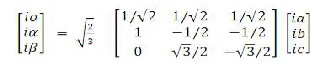
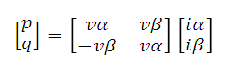
3.3 Instantaneous Power Theory:
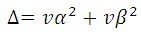
Proposed theory[6] based on instantaneous values in three-phase power systems with or without neutral wire, and is valid for steady-state or transitory operations, as well as for generic voltage and current waveforms called as Instantaneous Power Theory[7] or Active- Reactive (p-q) theory which consists of an algebraic transformation (Clarke transformation) of the three-phase voltages in the a-b-c coordinates to the a-�-
0 coordinates, followed by the calculation of the p-q
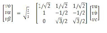
theory instantaneous power components.
Here va,vb,vc are(voltages at load) converted into vo,va,v�
by using above matrix[8]
Here ia,ib,ic (load currents)converted into io,ia,i�
by using above matrix

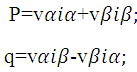 Real and reactive power
So from the above equations active and reactive powers are obtained
Above equations pandq can be written in a matrix form
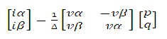
p and q are converted in to by using ia,i�.
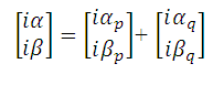
so finaly we can obtain ica*,icb*,icc*.
3.4 Block Diagram :
Active filters produce a nearly sinusoidal supply current by measuring the harmonic currents and then injecting them back into the power system with a 180° phase shift.
The output waveform is thus the harmonic power which is recognized as containing only current harmonics.
This is justified as once can assume a perfectly sinusoidal voltage source by virtue of the integrated positive sequence voltage detector.
IJSER © 2011 http://www.ijser.org
International Journal of Scientific & Engineering Research Volume 2, Issue 5, May-2011 7
ISSN 2229-5518
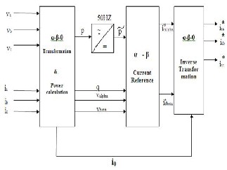
Fig:6 Reprsenting instantaneous power theory
3.5 Hysterisis current controller:
A controlled current inverter is required to generate this compensating current. Hysteresis current control is a method of controlling a voltage source inverter so that an output current is generated which follows a reference current waveform. This method controls the switches in an inverter asynchronously to ramp the current through an inductor up and down so that it tracks a reference current signal. Hysteresis current control is the easiest control method to implement.
A hysteresis current controller is implemented with a closed loop control system and is shown in diagrammatic form in Fig 7. An error signal, e(t), is used to control the switches in an inverter. This error is the difference between the desired current, iref(t), and the current being injected by the inverter, iactual(t). When the error reaches an upper limit, the transistors are switched to force the current down. When the error reaches a lower limit the current is forced
to increase. The minimum and maximum values of the error signal are emin and emax respectively.
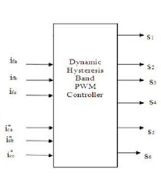
Fig: 7 block diagram
The range of the error signal, emax – emin, directly controls the amount of ripple in the output current from the inverter and this is called the Hysteresis Band.
The hysteresis limits, e min and e max, relate
directly to an offset from the reference signal and are referred to as the Lower Hysteresis Limit and the Upper Hysteresis Limit. The current is forced to stay within these limits even while the reference current is changing.
So these switching pulses s1,s2,s3,s4,s5,s6 are given to
the voltage source inverter,that will produce harmonic current to compensate the harmonic current produced by non linear load.
4 SIMULATION RESULTS WITH FFT
ANALYSIS
4.1 Open Loop with Voltage source inverter as a
Filter with one load:
IJSER © 2011 http://www.ijser.org
International Journal of Scientific & Engineering Research Volume 2, Issue 5, May-2011 8
ISSN 2229-5518
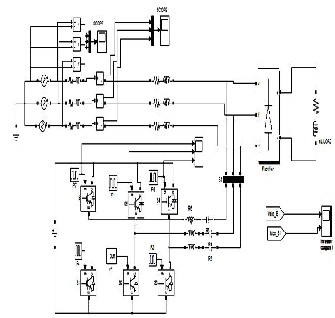
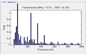
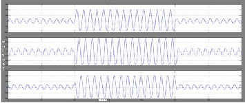
Fig: 10 FFT Analysys Of Load Current with one load
Here open loop with one load (power electronic load) is used,line voltage of vsi and fft analysis for load
current is taken.
Fig 8: Open Loop with Voltage source inverter as a Filter with one load
The voltage source inverter used in the active power filter makes the harmonic control possible. This inverter uses a D.C capacitor. as the supply and can switch at a high frequency to generate a signal which will cancel the harmonics from the nonlinear load. Here a VSI with 1800 mode is used which will reduce the T.H.D.
4.1.1 Voltage source inverter output:
Here filter is taken with voltage source inverter to reduce higher order harmonics.
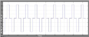
Fig:9 Voltage source inverter out put
4.1.2 FFT Analysys Of Load Current with one load:
4.2 Open loop circuit with composite load:
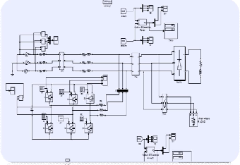
Fig:11 open loop system with both linear and non-linear load
Open-loop systems sense the load current and the harmonics it contains. They inject a fixed amount of power in the form of current (mainly reactive) into the system, which may compensate for most of the harmonics and/or reactive power available. Since there is no feedback loop on this system, there is no reference to check the performance and accuracy of the filter.
4.2.1 Fft analysis of load current:
Here we can observe in open loop system higher order hormonics are reduced.Here as another load is added to the system at system total hormonic current distortion
will be increased.
IJSER © 2011 http://www.ijser.org
International Journal of Scientific & Engineering Research Volume 2, Issue 5, May-2011 9
ISSN 2229-5518
Fig:12 fft analysis of load current
4.3 Closed loop system:
Closed loop control systems incorporate a feedback loop providing greater accuracy of current injection for harmonic compensation as well as reactive power reduction well over the open loop design.
Here in the closed loop system a reference current
is generated. This reference current is generated by using instantaneous power theory based on active power filter
.This current is given input to the hysteresis current
controller and compared with the one the phase current.
So these two currents are compared and an error will be produced this error given to the hysteresis loop band. In the hysteresis control technique the error function is centered in a preset hysteresis band. When the error exceeds the upper or lower hysteresis limit the hysteretic controller makes an appropriate switching decision to control the error within the preset band.
4.3.1 Closed Loop Simulation Circuit:
Closed loop control systems incorporate a feedback loop providing greater accuracy of current injection for harmonic compensation as well as reactive power reduction
well over the open loop design.
Fig:13 closed loop
4.3.2 Triggering pulses :
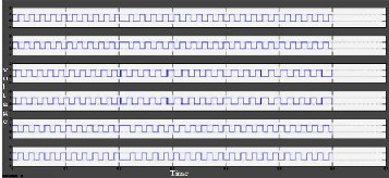
Fig:14 Triggering pulses obtained by hysteresis controller
4.3.3 Compensating voltage:
IJSER © 2011 http://www.ijser.org
International Journal of Scientific & Engineering Research Volume 2, Issue 5, May-2011 10
ISSN 2229-5518

Fig: 15 Compensating current in open loop
4.3.4 Compensating current in closed loop:
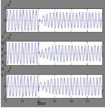
Fig:16 compensating current in closed loop
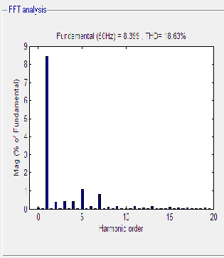
4.3.8 Fft analysis of load current:
Fig: 17 FFT analysis for load current
4.4 Comparison:
Table 2:Total Harmonic Distortion Comparison Table
CONCLUSION
A current decomposition technique based on instantaneous power theory for shunt active power filters is studied, a simu link model is designed and total harmonic distortion is calculated using FFT analysis.Active power filter which has been used here monitors the load current constantly and continuously adapt to the changes in load harmonics. The performance of three phase shunt active power filter using instantaneous power theory with PI and hysteresis current controller is explained in this paper.
ACKNOWLEDGMENT
This work is affiliated to the “Power Quality Improvement “which has been supported by SRM University, Department of Electrical and Electronics
Engineering.
IJSER © 2011 http://www.ijser.org
International Journal of Scientific & Engineering Research Volume 2, Issue 5, May-2011 11
ISSN 2229-5518
REFERENCES
[1] Schlabbach, D. Blume, and T. Stephanblome, “Voltage Quality in Electrical Power Systems”, ser. PEE Series. New York: IEE Press,2001.
[2] L. Gyugyi and E. C. Strycula, “Active AC power filter,” in
Proc. IEEE IAS Annu. Meeting, 1976, pp. 529–529.
[3] H. Akagi, Y. Kanazawa, and A. Nabae, “Generalized theory of the instantaneous reactive power in three-phase circuits,” in Proc. IEEE and JIEE IPEC, 1983, pp. 821–827.
[4] Y. Komatsu and T. Kawabata, “Experimental comparison of pq and extended pq method for active power filter,” in Proc. EPE, 1997, pp.2.729–2.734
[5] V. Soares, P. Verdelho, and P. D. Marques, “Active power filter control circuit based on instantaneous active and reactive current id – iq method,” in Proc. IEEE PESC, 1997, pp. 106–101.
[6] B. Singh, K. Al-Haddad, and A. Chandra, “A new control approach to three-phase active filter for harmonics and reactive power compensation,”
[7] IEEE Trans. Power Syst., vol. 13, no. 1, pp. 133–138, Feb. 1998.
“Active power filters for non-linear loads”.Instantaneous Power Theory Based Active Power Filter: A Mat lab/ Simulink Approach.
[8] Generalized theory of the instantaneous reactive power in three-phase circuits,” in Proc. IEEE and JIEE IPEC, 1983, pp.
821–827.
[9]Harashima F., Inaba H. and Tsuboi K., “A close-loop control system for the reduction of reactive power required by electronic converters,”Toshiba Electric Co., Tokyo, Japan, Oct. 1975.
[10]Knoell H., “3 kW-switch-mode supply providing
Sinusoidal mains current and large range of dc-output,” PCI, Munich, Germany, 1980.
[11]Nastran J.. “Active Power Filter,” dissertation presented at the Faculty of Electrical Engineering, Ljubljana,
Yugoslavia,1985..
IJSER © 2011 http://www.ijser.org