International Journal of Scientific & Engineering Research, Volume 4, Issue 9, September-2013 431
ISSN 2229-5518
1Dr. S. Shivakumar 1 Dr. Anupama N Kallol , 2Vishwanath Khadakbhavi
1Professor , Dept. of I and P Engg, Gogte Institute of Technology, Belgaum, Karnataka,India
2PG Student, Product Design & Manufacturing, Visvesvaraya Technological University, Belgaum,
1sshivakumar@git.edu, 3vishi_mk@yahoo.co.in
The machine tool spindle provides the relative motion between the cutting tool and the workpiece which is necessary to perform a material removal operation. In turning, it is the physical link between the machine tool structure and the workpiece, while in processes like milling, drilling or grinding, it links the structure and the cutting tool. This work deals with design and analysis of Lathe Spindle in which the material used for the spindle is alloy steel. The spindle is supported by two bearings separated by different spans. Bearings consist of balls with certain stiffness, which acts as a cushioning effect for the spindle and hence can be considered as a spring in the software (Ansys) for analysis.
Keywords: Spindle, Bearings, FEM
1. INTRODUCTION
The basic structure of a machine tool consists of base and column arrangement which serves as a balancing support for the entire machine. Here, depending on the machining process, the tool is fixed in the tool post and the work piece is held on the chuck of a typical lathe structure. The relative motion is achieved by movements parallel to the three spatial axes. This is achieved by means of linear guide ways and bearings, axial movements along the screws, rack and pinion arrangements etc. The machine is built of heavy steel and iron parts. The base of the machine is rigid and usually is of cast iron
The present machine tool structures consist of spindle system which play a vital role in
the quality of the final product and enhances the overall productivity and efficiency of the machine tool itself.The spindle of a machine, which is rotated by the spindle motor holds the cutting tool, which cuts the work piece, so that it influences the accuracy directly. For instance in machining centers the spindle system could alone account for about 30 to 40 % of stiffness at cutting point between tool and work piece.
Applying the FEM method for modeling a system comprised of an inner and outer race of the bearing and the rolling element between them is considered for the work. This method is being developed for computing the stiffness of the roller bearings and ball bearing. Correct modeling of bearing is one of important conditions for obtaining correct results of simulation; hence it will reduce the number of laboratory tests. It is expected that the results obtained with use of the model developed will allow the determination of stiffness of the bearing.
In the discussed calculation method, it was assumed that the bearing stiffness depends on the stiffness of the outer race, inner race, each rolling element being under load. This stiffness is nonlinear functions of load imposed on the rolling element, thereby dependent on its position in relation to the direction of the force. Such approach allows taking into consideration resulting from the changeable bearing stiffness caused by both, changes in the position of rolling elements in relation to the direction of the force and damage and wear and tear of the interacting bearing elements
In the present work the static analysis and dynamic analysis is carried out for spindle
IJSER © 2013 http://www.ijser.org
International Journal of Scientific & Engineering Research, Volume 4, Issue 9, September-2013 432
ISSN 2229-5518
supported on two front bearings and a rear bearing. For the analysis of structure the minimum deflection region near loading point is considered. Bearing stiffness value will be calculated by an iteration procedure, life of bearings is calculated using numerical relations and this paper also describes the modifications required to correct the bearing span so as to get more stability for spindle.
The following are the project specifications for the spindle structure
Angular contact ball bearing (α=15) Cutting conditions: speed (n) =1200 rpm Power (p) =2 kW
Cutting diameter (φ) =25.4mm
Tangential cutting force (Fr) =2000N Axial cutting force (Fa ) = 700N
Load is at 110 mm away from spindle nose.
The objective of this work is
1) To carry out the static and dynamic analysis of
spindle structure by optimizing the bearing span.
2) Predicting life of bearings.
3) Carrying out the Von mises stress & harmonic
analysis.
4) Developing the Mode Shapes to check the vibration characteristics.
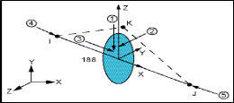
BEAM188 is suitable for analyzing slender to moderately stubby/thick beam structures. This element is based on Timoshenko beam theory. Shear deformation effects are included.
COMBIN-14 has longitudinal or torsional capability in one, two, or three dimensional applications. The longitudinal spring-damper option is a uniaxial tension-compression element with up to three degrees of freedom at each node: translations in the nodal x, y, and z directions. No bending or torsion is considered. The torsional spring-damper option is a purely rotational element with three degrees of freedom at each node: rotations about the nodal x, y, and z axes. No bending or axial loads are considered.
• Young’s modulus – 2.1e5 N/mm2
• Poisson’s ratio - 0.3
• Density – 7.8 e-9 kg/mm3
• Cutting Diameter – 25.4 mm
• Speed=1200 rpm
• Front bearings – Ø65 × Ø 120 mm
• Rear bearing – Ø 65 × Ø 120 mm
Load at 110 mm away from spindle nose in radial direction = 2000N
Load at 110 mm away from spindle nose in Axial direction = 700N
K y = C13 = - C19 = C64 = 84986
Kz = C24 = -C30 = C69 = 84986
Kx = C1=-C7=C58= 2511.5
Ky = C13 = -C19 = C64 = 69732
Kz = C24 = -C30 = C69 = 69732
Kx = C1=-C7=C58= 2509.25
IJSER © 2013 http://www.ijser.org
International Journal of Scientific & Engineering Research, Volume 4, Issue 9, September-2013 433
ISSN 2229-5518
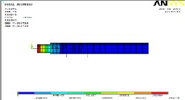
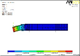
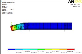
The Finite Element Model with the boundary conditions is submitted in Ansys for Static Analysis. As for output request FEM model results of spindle are obtained which include mainly deflection. For checking the deflections of spindle in axial and radial direction go for sub grid solution under query results mode.
Iterative procedure:-
![]()
Q = 5Fr
iZ cos α
![]()
Q = 5 × 203.87
1×17 cos15
Q=62.08 Kgf
δr =
0.002 2
![]()
cos α Dw
δr =
![]()
0.002 cos 15
62.082
3
15.4
δr =0.0130446 mm
![]()
Q = 5Fa
iZ sin α
![]()
Q = 5 × 71.35
1×17 sin 15
Q=81.081 Kgf
δa =
0.002 Q2
3
![]()
sin α Dw
δa =
![]()
0.002 sin 15
81.0812
3
15.4
IJSER © 2013 http://www.ijser.org
International Journal of Scientific & Engineering Research, Volume 4, Issue 9, September-2013 434
ISSN 2229-5518
δa =0.0581812 mm
P
![]()
5 × 35.68
Q = 1 × 17 sin 15
Q=40.55![]()
Kr =
δr
![]()
Kr =
2000
0.0130446
Kr=153320.14 N/mm
δa =
0.002 Q 2
3
![]()
![]()
sin α Dw
![]()
Ka = P
δa
δa =
![]()
0.002 sin 15
40.552
15.4
Ka =
700
![]()
0.0581812
δa =0.079824 mm
Ka=12,031.3778 N/mm
![]()
P Kr =
r
![]()
4212.4
Kr =
0.0211004![]()
Q = 5Fr
iZ cos α![]()
5 × 421.24
Q = 1 × 17 cos 15
Q=128.26 Kgf
Kr=200590.47 N/mm![]()
P
Ka =
a
![]()
350.07
Ka = 0.079824
Ka = 4385.52 N/mm
δr =
![]()
![]()
![]()
0.002 cos α
0.002
Q 2
3
Dw
128.262
δr =
cos15
3
15.4
δr =0.0211604 mm
![]()
Q = 5Fa
iZ sin α
IJSER © 2013 http://www.ijser.org
International Journal of Scientific & Engineering Research, Volume 4, Issue 9, September-2013 435
ISSN 2229-5518

(a)Axial
Iteratio
IJSER © 2013 http://www.ijser.org
International Journal of Scientific & Engineering Research, Volume 4, Issue 9, September-2013 436
ISSN 2229-5518
(a)Axial

n
T nrd
IJSER © 2013 http://www.ijser.org
International Journal of Scientific & Engineering Research, Volume 4, Issue 9, September-2013 437
ISSN 2229-5518
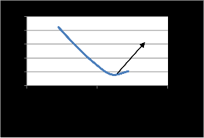
By looking in to Table 6 it can be decided that the optimum bearing span having length 240 mm has got minimum deflection.
0.18
0.16
0.14
0.12
0.1
0.16460
0.13717
0.11659
Minimum deflection
0.10082
Modal analysis is used to determine the vibration characteristics (natural frequencies and mode shapes) of a structure or a machine component while it is being designed. It can also be a starting point for another, more detailed, dynamic analysis,
0.08
0.09602
0 200 400
such as transient dynamic analysis, a harmonic
response analysis, or a spectrum analysis.
The spindle model is now subjected to modal analysis. The Table 6.9 shows the frequencies at which the model resonates. Machine frequency when maximum rpm condition is taken is 20 Hz. The mode shapes obtained must be away from this frequency range so as to make that resonance does not occur.
IJSER © 2013 http://www.ijser.org
International Journal of Scientific & Engineering Research, Volume 4, Issue 9, September-2013 438
ISSN 2229-5518
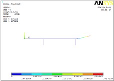
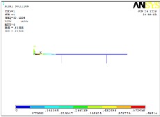
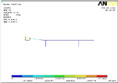
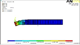
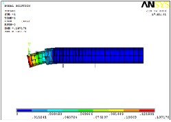
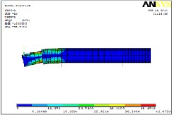
Fig 9 shows the mode shape 1 at freq 30.11 Hz. It can see from the Fig that the mode shape is only in vertical direction at loading point
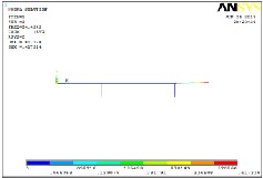
Fig 10 shows the mode shape 2 at freq 30.11 Hz It can be seen that there is bending mode in vertical direction at loading point
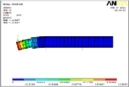
Fig 11 shows the mode shape 3 at freq 34.42 Hz. It can be seen that there is bending mode in vertical direction on other direction of the loading point.
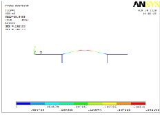
Fig 12 shows the mode shape 4 at freq 34.42 Hz. It can be seen that there is bending mode in vertical direction on other direction of the loading point.
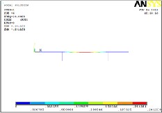
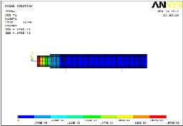
Fig 13 shows the mode shape 5 at freq 38.85 Hz. Here in this mode bending mode is in horizontal direction at the center of the structure.
Fig 14 shows the mode shape 6 at freq 38.85 Hz. Here in this mode bending mode is in horizontal direction at the center of the structure.
IJSER © 2013 http://www.ijser.org
International Journal of Scientific & Engineering Research, Volume 4, Issue 9, September-2013 439
ISSN 2229-5518
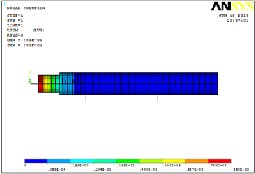
According to the von Mises’s theory, a ductile solid will yield when the distortion energy density reaches a critical value for that material. Since this should be true for uniaxial stress state also, the critical value of the distortional energy can be estimated from the uniaxial test. At the instance of yielding in a uniaxial tensile test, the state of stress in terms of principal stress is given by: σ1 = σY (yield stress) and σ2 = σ3 = 0
Thus, the energy density is the critical value of the distortional energy density for the material. Then
according to von Mises’s failure criterion, the material under multi-axial loading will yield when the distortional energy is equal to or greater than the critical value for the material. Thus, the distortion energy theory can be stated that material yields when the von Mises stress exceeds the yield stress obtained in a uniaxial tensile test.
For bearing of 240 mm span which is optimized value voin misses stresses are calculated using the ansys software and the results are as shown in the fig 4.14. So allowable stress for steel is much higher than the results found in the software. So material is well within safe condition.
Harmonic response analysis is a technique used to determine the steady-state response of a linear structure to loads that vary sinusoidally
(harmonically) with time. The idea is to calculate the structure's response at several frequencies and obtain a graph of some response quantity (usually displacements) versus frequency. "Peak" responses are then identified on the graph and stresses reviewed at those peak frequencies.
It is required to carry out harmonic analysis to confirm whether the spindle is resonating within the operating range of the spindle. The operating range is the range of spindle speeds which varies up to 1200 RPM (1200/60= 20
Hz).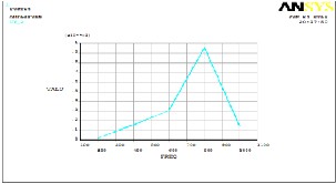
The Fig4.14 shows that the maximum amplitude is
0.0095 mm. Maximum amplitude is of our concern and it is not in the range of working frequency. So thus it has negligible effect.
Its application has been carried out for practical All Geared lathe with 2kW spindle and spindle speed of 1200 rpm. The application showed the utility of the above procedure for modeling spindle systems and as an application optimum bearing span of bearings has been calculated, natural frequencies and mode shapes of the spindle have been calculated.
1] Optimum bearing span of 240 mm is considered for fixing distance between front and rear bearings.
2] The vibration analysis showed that no resonance occurs predicted results are verified with analytical models.
3] Von mises Stress Analysis shows that deflection is on the safer side.
From results and discussions deflection
value for the 240 mm bearing span is 0.096021 mm. Radial and axial stiffness values are calculated for front bearings while for rear bearing only radial stiffness is calculated since if rear bearing is constrained there will be thermal deformation which leads to buckling therefore there will negligible axial stiffness.
The simplified approach has been developed for analysis of spindle supported on
IJSER © 2013 http://www.ijser.org
International Journal of Scientific & Engineering Research, Volume 4, Issue 9, September-2013 440
ISSN 2229-5518
two bearings is developed an iterative procedure is presented for computing reactions of bearings under load and also for calculating bearings stiffness in general 3 to 4 iterations are sufficient to get convergent results. The procedure makes use of beam188 element for spindle and Combin14
Spring Damper element for springs.
[1]. Joaquim de Ciurana, Guillem Quintana and Francisco Javier Campa, “Machine tools for high performance machining”,Machine tool spindles, 2009,
75-127, DOI: 10.1007/978-1-84800-
380-4_3
[2]. Dr.Sinan Badrawy, “Dynamic modelling
and analysis of motorized milling spindles for optimizing the spindle cutting performance”, Engineering Manager Moore Nanotechnology Systems, LLC.
[3]. Syath Abuthakeer.S, Mohanram.P.V, Mohan Kumar.G, “Dynamic characteristics analysis of high speed motorized spindle”, International journal of engineering, Vol 9,Pages 219-224,
2011
[4]. Osamu Maeda, Yuzhong Cao, Yusuf Altintas, “Expert spindle design system” International Journal of Machine Tools & Manufacture 45 (2005) Pages537–548.
[5]. Al-Shareef.K.J.H, Brandon. J.A, “Validity of several common assumptions in the design of machine tool spindle-
bearing systems”, Vol 31, Issue 2, Pages
235–248, 1991.
[6]. Momir Sarenac, “Stiffness of machine
tool spindle as a main factor for treatment accuracy”, The scientific journal, Vol.1, No 6, Pages 665 – 674, 1999.
[7]. Ertu rka. A, zgu vena. H.N. O, Budakb
.E, “Analytical modeling of spindle–tool dynamics on machine tools using
Timoshenko beam model and receptance coupling for the prediction of tool point FRF”, International Journal of Machine Tools and Manufacture Vol 46 , Pages
1901–1912, 2006.
[8]. Deping Liu, Hang Zhang, Zheng Tao and
Yufeng Su, “Finite Element Analysis of
High-Speed Motorized Spindle Based on
ANSYS”, School of Mechanical
Engineering, Zhengzhou University, Zhengzhou1, China.
[9]. Thitima Jintanawan, “Effects of distributed bearing forces and bearing locations on rocking vibration of FDB(Fluid dynamic bearings) spindle systems”, ASME Information Storage and Processing Systems Conference, 2005
[10]. Al-Shareef.K.J.H, Brandon. J.A, “Effects
of variations in the design parameters on the dynamic performance of machine tool spindle-bearing systems”, International Journal of Machine Tools and Manufacture, Vol 30, Pages 431–445,
1990.
[11]. Rathour . A. N, Darji P. H, “Design, development and analysis of high speed spindle: a review” Department of Mechanical Engineering, C. U. Shah College of Engineering and Technology, Surendranagar, Gujarat.
[12]. Machine tool design hand book by central
machine tool institute, Bangalore.
[13]. Ball and roller bearing engineering by palmgren.A, Third edition 1959, burkank
and co,Philadelphia
[14]. Luk, Y.W. and Mitchell, L.D, “System modeling and modification via modal
analysis”, Proceedings of the first Int
IJSER © 2013 http://www.ijser.org