International Journal of Scientific & Engineering Research, Volume 2, Issue 11, November-2011 1
ISSN 2229-5518
A Wireless Based Real-time Patient Monitoring
System
Sowmyasudhan S, Manjunath S
Abstract - The paper demonstrated gives the complete idea on a system which uses four smart sensors to detect the respective four pathological parameters of a baby or a person and interfacing the cell phone to this system to alarm the doctors. The smart sensors senses the biomedical signal of the subject under study (here subject means a baby or a person with pathological disorders) and executes with the controlled coding of the mother processor that is microcontroller and further it hooks the wireless cell phone and using the application software, TEXT application protocol of the cell phone to alarm the respective doctors. With this idea to save energy by consuming the cell phone battery and to help out peop le below poverty line to contact experienced doctors, who are out of reach and they by analysis is done perfectly. No external source is used for triggering the alarm. Using wireless-based low cost to monitor real-time pathological parameters of the subject and say it as a simple biomedical-caring system. The system keeps an extra eye on the pathological parameters of subject under test/babies at home/ICU. The intelligent system consists of detector circuit and mobile display unit at the receiver section. The detector circuit uses different application sensors to detect health condition of the subject at the source. The mobile display unit is used to visualize the health situation by using the text based application on the cell phones by a doctor or concerned person. The standard for mobile telephony that has been used in this project is wireless communication. The ubiquity of implementation of the wireless standard has been an advantage to both consumers, who may benefit from the ability to roam and switch carriers without replacing phones, and also to network operators, who can choose equipment from many wireless equipment vendors. Wireless also pioneered low-cost implementation of the short message service (SMS), also called text messaging, which has since been supported on other mobile phone standards as well. The standard includes a worldwide emergency telephone number feature. So, the main aim of this project is to get information about the condition of the critical subject which needs to be monitored round the clock, which is in ICU through wireless. The wireless Transmitter sends the details about incubator's temperature, voice level , heart rate and its movement to the destination point which is a doctor’s mobile and these details are displayed on the mobile scree n in the form of SMS’s, so that the doctor can analyze the condition from the place where he is sitting. This is the most basic foundation in the area of telemedicine application.
Index Terms- Wireless Communication, Smart Sensors, Tele-medicine, 24*7 Monitoring.
1. INTRODUCTION
—————————— ——————————
acquisition from the transmitter section, secondly the signal
In recent world continuous monitoring of the pathological
parameters is an important challenge , which consumes more memory units and need more complex processing processor which count for more money .In this case, the continuous inspection of the pathological subject which is in the intensive care unit is done using indicators and sensors. The outputs of these sensors, indirectly or in some form, are connected to indicators.
If the subject is in good health condition, made by decision algorithm within the processor designed at standard values then the indicator will alarm “BABY IS NORMAL”, otherwise it will alarm “BABY IS ABNORMAL”. This study finds vast application in the remote places where the people are out of reach from the experienced doctors; keeping this factor in mind best effort is done to implement some of the basic test of pathological data on the system. Hence the entire project can be broadly divided into four sections firstly, the signal

SOWMYA/CSE/ATME/sowmya.atme@gmail.com
MANJUNATHA S/ECE/ATME/atmemanju@gmail.com
processing and conversion to digital form; thirdly decision making with the help of an algorithm where they obtained signal values are compared with the standard values and finally the transmission of the condition of the patient to the destination.
2. SCHEMATIC LAYOUT OF THE DESIGN
IJSER © 2011 http://www.ijser.org
International Journal of Scientific & Engineering Research, Volume 2, Issue 11, November-2011 2
ISSN 2229-5518
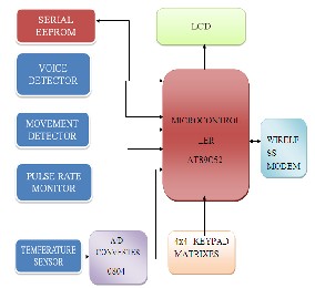
Block diagram 1: WIRELESS Based real-time patient
Monitoring System
Hence the entire paper can be broadly divided into four sections:
Firstly, the signal acquisition from the transmitter section, Secondly the signal processing and conversion to digital form if necessary,Thirdly decision making with the help of an algorithm where they obtained signal values are compared with the standard values and; Finally the transmission of the condition of the patient to the destination.Firstly regulated power supply is used to regulate the supply to 5v DC and it is given to the microcontroller. Sensors continuously monitor and provide analog/digital signals in response to inputs of various features of the patient like temperature, voice, heart beat and movement and these outputted signals can be read by a reader or an instrument. Usually the sensor signal is weak in nature and hence it requires processing. The processing may include amplification and noise cancellation. The amplified signal is converted into the corresponding digital signals if required using an analog to digital converter by means of
which, it provides the easiest way to communicate. These
digital processed signals are given to a decision algorithm which is previously written in the form of HEX code within the microcontroller and stored in the memory of a microcontroller. These signals are compared with the standard statistics of a normal standard values. Finally the data/ health condition of the subject is transmitted to the doctor (receiving wireless device). LCD displays are used to display the good and bad conditions of the patient. Buzzer/SMS acts as an indicator to indicate abnormal condition of a patient under observation and the doctor can take immediate action.
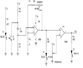
3. SENSOR CIRCUITS
Circuit diagram 2 & 3: LM35 sensor circuit and Voice
Detecting/Amplifying Circuit
Circuit diagram 4: PIR Sensor Based Movement Detector
IJSER © 2011 http://www.ijser.org
International Journal of Scientific & Engineering Research, Volume 2, Issue 11, November-2011 3
ISSN 2229-5518
Circuit diagram 5: LDR Sensor
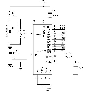
4. CIRCUIT EXPLANATION FOR TEMPERATURE SENSOR
The LM35 temperature sensor directly senses 10mv for every
1degree centigrade directly, which is more advantageous the baby under test should be provided so as to touch the sensor, Once the vital signs so obtained is digitized using analog to digital convertor chip 0804 using SAR method .In order to process ac signals, SAR ADCs must have an input sample-and- hold (SHA) to keep the signal constant during the conversion cycle. On the assertion of the CONVERT START command, the sample-and-hold (SHA) is placed in the hold mode, and the internal DAC is set to midscale. The comparator determines whether the SHA output is above or below the DAC output, and the result (bit 1, the most significant bit of the conversion) is stored in the successive approximation register (SAR). The DAC is then set either to ¼ scale or ¾ scale (depending on the value of bit 1), and the comparator makes the decision for bit 2 of the conversion. The result is stored in the register, and the process continues until the entire bit values have been determined. The 8-bit pulse format data is input to the microcontroller via port 1.A protection circuit is designed using a zener diode LM330 of 2.5V for the reverse flow of the voltage back to the microcontroller. With the provided pot in the circuit the threshold of the temperature can be varied.
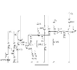
4.1 CIRCUIT EXPLANATION FOR VOICE SENSOR
The condenser microphone senses the burst of cry from the paralyzed subject under test ,the wave motion thus creates a change in the capacitance value in the microphone there by generating the electric signal of very low amplitude in terms of
0.001 mv .The common emitter type configuration with voltage divider biasing circuit three level of multistage amplifier with the gain factor of 10.Thus the output from the amplifier is suitable enough to activate the main processor that is microcontroller. If the cry burst is greater than the 12 cry burst threshold the processor alarms the doctor.
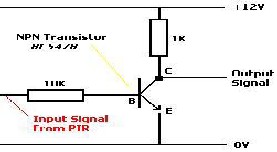
4.2 CIRCUIT EXPLANATION FOR MOVEMENT SENSOR
The PIR sensor with the Fresnel’s cavity with the viewing angle of 180 degrees keeps on tracking for the random movement of the baby under observation , the infrared radiations creates a pit in the chip thus generates the electrical signal , the human body radiates approximately 8 to 12 micrometers of IR radiations. If the baby moves randomly the values of the radiation pits changes randomly and generates a very low frequency small amplitude signal .If so sensed values doesn’t limits within the range of 10 inches it alarms. When the PIR sensor detects the movement of a warm body the integrated LED Indicator lights up for a second or two. When the LED is not lit, C and NC are connected. When the LED is lit C and NC are not connected. Everything would be a lot easier for us if it worked the other way around - i.e. C and NC only connected when motion is detected, however a simple transistor inverter NOT gate can be used to invert the output signal.
So, when the PIR sensor unit detects motion, the LED lights
up, the PIR Sensor signal is 0V which is then inverted to an output signal of +12V (by our simple NOT gate). When no motion is detected, the LED is not lit, the PIR sensor signal is
+12V which is then inverted to an output signal of 0V.The
output signal can then be connected across the coil of a relay, a
12 Volt LED spotlight, or a buzzer/alarm for example. However, the device (or circuit) connected to the output from
the NOT gate circuit will only receive power for as long as the
IJSER © 2011 http://www.ijser.org
International Journal of Scientific & Engineering Research, Volume 2, Issue 11, November-2011 4
ISSN 2229-5518
LED indicator is lit on the PIR sensor unit - a couple of seconds at most.
The human body radiates infrared waves with wavelengths of
8 to 12 micrometers. Any movement by a person leads to a change in the amount of infrared energy which a sensor can detect within its range. The PIR sensor reacts to this change in infrared energy and provides a low- frequency, small amplitude signal. The sensor can sense the change in the amount of infrared energy within small distances, approximately up to 10 inches. For detecting movements at longer distance, infrared radiation has to be focused. This focusing is done by a Fresnel lens. A Fresnel lens divides the whole area into different zones. Any movement between zones leads to a change in the IR (infrared) energy received by the sensor. There are different types of Fresnel lenses depending on the range (distance) and coverage angle. Thus a person entering a monitored area is detected when the infrared energy emitted from the intruder's body is focused by a Fresnel lens or a mirror segment and overlaps a section on the piezoelectric sensor chip that had previously been looking at some much cooler part of the protected area. That portion of the chip is now much warmer than when the intruder wasn't there. As the intruder moves, so does the hot spot on the surface of the chip. This moving hot spot causes the electronics connected to the chip to de-energize the relay, operating its contacts, thereby activating the detection input on the alarm control panel. Conversely, if an intruder were to try to defeat a PID, perhaps by holding some sort of thermal shield between himself and the PID, a corresponding 'cold' spot moving across the face of the chip will also cause the relay to de-energize unless the thermal shield has the same temperature as the objects behind it.
4.3 CIRCUIT EXPLANATION FOR PULSE RATE SENSOR Heart rate can be measured either by the ECG wave form or by the blood flow into the finger (pulse method). The pulse method is simple and convenient. When blood flows during
the systolic stroke of the heart into the body parts, the finger gets its blood via the radial artery on the arm. The blood flow into the finger can be sensed photo electrically. To count the heart beats, here we use a small light source on one side of the finger (thumb) and observe the change in light intensity on the other side. The blood flow causes variation in light intensity reaching the light-dependent resistor (LDR), which results in change in signal strength due to change in the resistance of the LDR.
The heart rate sensor uses 650nm wavelength LDR light at the transmitter end and photo resistor at the receiver end so that the light penetrates the baby middle finger and reads the data of the pulse .The electrical signal are of 0.001mv (signal voltage is very low) so picked up are amplified with an op-amp to meet the specification of the microcontroller. Thus processed values are compared with the threshold of 81bpm and if the incoming sample value is greater than threshold microcontroller alarms the doctor via cell phone.
5. SOFTWARE IMPLEMENTATION EXPLANATION OF THE ALGORITHM
After the processing of the signals which are got from the sensors,
They are converted into digital if necessary and are given to a decision algorithm which is previously written in the form of code and it is stored in the memory of a microcontroller.
These signals are compared with the standard statistics of a normal standard values.
Hence the continuous inspection of the patient which is in the intensive care unit is done using indicators and sensors. The output of the sensors, indirectly or in some form are connected to indicators. If the patient is in good health condition, then the indicator will display “BABY IS NORMAL”, otherwise it will display “BABY IS ABNORMAL.
It should be noted that: If the patient is normal, then no warning/alert messages are sent to the doctor; otherwise the doctor receives alert messages which indicate him to attend the
patient immediately.
IJSER © 2011 http://www.ijser.org
International Journal of Scientific & Engineering Research, Volume 2, Issue 11, November-2011 5
ISSN 2229-5518
6. SIMULATED RESULT ANALYSIS
A WIRELESS BASED REAL-TIME PATIENT MONITORING SYSTEM analysis or provides a basic testing system which find wide range of application in telemedicine area , where the child from remote place can take the advantage with the latest medical prescription. The aim in this project is to develop a small compatible universal real-time system to alarm the doctor in-charge anywhere in the world, if the patient experiences abnormal conditions. The testing four basic main parameters like, Temperature, Voice, Heart-Rate and Movement. The standard parameters are loaded on to an external memory EEPROM, (provided by doctors as listed in the table).The external memory is interfaced to the microcontroller, whenever the system is ON the microcontroller reads the standard data and compares with the incoming data from each respective sensors. If the microcontroller observes that the incoming processing sample value is deviated from the standard values it alarms the Wireless modem and takes suitable action in informing the doctor in-charge and the nurse depending upon the mobile numbers provided in the program .A facility for three mobile numbers which can be enhanced in future depending upon requirement.
With the overview that the system still needs to be enhanced
before putting it under practical test. Much care has to be taken while testing the baby, because a small reverse voltage may paralyze the baby definitely.
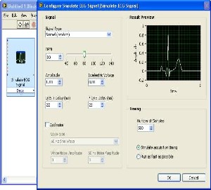
6.1:LM35 AS TEMPERATURE SENSOR:
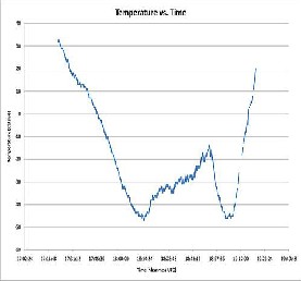
Figure 6: OUTPUT SIMULATION OF TEMPERATURE SENSOR LM35
Figure 7: INPUT SIGNAL TO TEMPERATURE SENSOR LM35

Figure 8: OUTPUT SIMULATION WAVEFORM OF TEMPERATURE SENSOR LM35
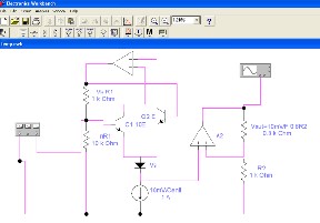
6.2: LDR AS PULSE –RATE SENSOR:
IJSER © 2011 http://www.ijser.org
International Journal of Scientific & Engineering Research, Volume 2, Issue 11, November-2011 6
ISSN 2229-5518

Figure 9: SNAP SHOT SHOWING CIRCUIT DIAGRAM OF LDR SENSOR
Figure 10: SIMULATION OUTPUT WAVEFORM OF LDR SENSOR (CIRCUIT) IN AMPLITUDE VS TIME
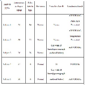
Table 1: Data’s summarizes the simulated result tested for
different pathological disorders
7. ADVANTAGES
1. Benefits to Physicians
i) Improved diagnosis and better treatment management. ii) Quick and timely follow-up of babies.
2. Benefits to Patients and also Parents
i) Reduced visit to hospitals for long term follow-up care.
ii) Earlier discharge of patients (babies) leading to shorter length of stay in hospitals.
3. Hospital Benefits
i) Significant reduction in unnecessary visits.
ii) Hospitalization for specialized care at tertiary hospitals.
8. APPLICATIONS
In Biomedical Fields:
Biomedical engineering is the application of engineering principles and techniques to the medical field. This field seeks to close the gap between engineering and medicine.
Remote Monitoring Purposes:
Remote Monitoring refers to accessing and monitoring a device from a distant location. At times it is not possible and feasible to monitor a device by being physically present along with it.
Remote Consultation:
IJSER © 2011 http://www.ijser.org
International Journal of Scientific & Engineering Research, Volume 2, Issue 11, November-2011 7
ISSN 2229-5518
A consultant is usually an expert or a professional in a specific field and has a wide knowledge of the subject matter. A consultant usually works for a consultancy firm or is self- employed, and engages with multiple and changing clients. Remote Consultancy is a way of service that experts with affluent operating theoretical knowledge and practical experience communicate with us directly.
9. CONCLUSION
From this project we can conclude that this can be one of the best methods for bio medical application where the doctors can analyze the subject condition from the place where they are sitting and hence proper and timely Medicare to the patient can be given so that percentage of childhood death can be reduced to larger extent.
FUTURE SCOPE
With the above mentioned system, keeping this as the basic foundation in Tele-medical fields we can built a more robust system that Integration of inpatient and out-patient services, creating user networks example: Tele-pathology, Case conference and research oriented Continued Medical Education. We can Increase In-patient Efficiency –Walk Into The Hospital Down load updated patient list, Down load list of new consultations ,Voice mail and Video mail ,Messages from physicians / nursing / patients / Patient’s family. With further 4-G technology we can build Wireless Long Distance [WiLD] Clinical Applications deliver expertise to anywhere in the world and medical Transportation. Apart from these task the main challenge still to human begins is implementation of Tele-surgery in Medical Education.
Acknowledgments
We are very much grateful to Mr. L. Arun Kumar, Chairman, Mr. K. Shivashankar, Member , Mr. R. Veeresh, Member , Dr. Srinivasan, Principal ,ACADEMY FOR TECHNICAL AND MANAGEMENT EXCELLENCE,. They have been a source of
inspiration and encouragement.
We would like to thank heart fully our college ACADEMY FOR TECHNICAL AND MANAGEMENT EXCELLENCE, our colleagues and students.
BIBLIOGRAPHY:
[1] www.sensorcompany.com
[2] http://www.citris-uc.org/system/files/16-Future-of- Telemedicine-by-Javeed.pdf
[3] http://www.isro.org/publications/pdf/Telemedicine.pdf
[4] http://www.alldatasheet.com/?gclid=CKGpzoyc_6ICFdFA6 wod3EVHbw
[5] http://www.spirometry.com/ENG/Products/telemedicine.as p?gclid=CIaFxpmc_
[6] http://www.niitprofessional.com/professional/?siteId=Komli
&adUnit=300x250 [7] www.google.com
[8] www.topic hunter.com
[9] www.epanoram.com
[10] http://www.nowsms.com/GSM%20Modems.htm
[11] http://www.nowsms.com/UCP.htm
[12] J. C. Lin, J. Kiernicki, M. Kiernicki and P. B. Wollschlaeger, "Microwave Techniques, IEEE Transactions on, vol. 27, pp.
618-620, 1979. C. J. Harland, T. D. Clark and R. J. Prance,
"Electric potential human body," Measurement Science and Technology, vol. 13, pp. 163-9, 2002. C. J. Harland, T. D. Clark and R. J.Prance, "Remote detection of human e input impedance electric potential sensors," Appl. Phys. Lett., vol.
81, pp. 3284-6, 2002.
IJSER © 2011 http://www.ijser.org