International Journal of Scientific & Engineering Research, Volume 6, Issue 3, March-2015 819
ISSN 2229-5518
A Review on Design Development of Multi-Link
5-Dimensional Coupling for Parallel Offset & Angular Transmission
Tushar B. Shinde Department of Mechanical Engineering S.V.C.E.T,Rajuri,
Pune,Maharashtra-412 411
tusharshinde33@gmail.com
ABSTRACT: The Five Dimensional Couplings are designed to accommodate 5 degrees of shaft misalignment. Five Dimensional Couplings offer two parallel misalignments and three angular misalignments capabilities. The acting forces within the coupling can be precisely calculated, assuring a sound coupling design which is especially important for heavy-duty applications. If these shaft misalignments exceed the limit of the selected coupling capacity, excess side loads are introduced into the equipment which can cause vibrations, life reduction or failure of vital machine components such as bearings, motors, etc.
The 5-D Couplings are a modification of the Inline Coupling, designed to accommodate 25 degrees of angular shaft misalignment. This coupling allows easy adjustment to any possible misaligned shaft position without imposing heavy side loads on shafts, bearings or other machine equipment. 5-D Couplings offer large shaft misalignment capabilities and constant angular velocity. The acting forces within the coupling can be precisely calculated, assuring a sound coupling design which is especially important for heavy-duty applications.
—————————— ——————————
INTRODUCTION:
PROBLEM DEFINITION-In any direct mechanical drive system, there exists a need to couple the variety of driven elements that may be included. The majority of drive elements, including gear reducers, lead screws, and a host of other components, are driven by shafting that is supported by multiple bearings. This allows for shafting to be held extremely straight and rigid while rotating, avoiding any possible balancing and support problems. Because of this rigid support, it is virtually impossible to avoid slight misalignments between a driving and driven shaft when they are connected. Restoring forces that occur as the two coupled shafts compete to maintain their original positions can put unwanted strain on shaft bearings, causing them to wear out prematurely. Additional axial loads are also placed on the bearings as thermal growth occurs in shafting during operation.The basic function of a power transmission coupling is to transmit torque from an input shaft to an output shaft at a given shaft speed and, where necessary ,to accommodate shaft misalignment. Misalignment is the result of many factors including installation errors and tolerance variations. Shaft misalignment can increase the axial and radial forces exerted on the coupling. In misaligned applications, undesirable side loads are usually introduced by the coupling. These side loads result from dynamic coupling behavior, frictional loads and loads caused by flexing or compressing coupling components. The undesirable results include:
1) Torsional or angular velocity vibrations which reduce system accuracy.
2) Excessive forces and heat on system bearings which reduce machine life.
3) Increased system vibration and noise which adversely affects equipment operation.
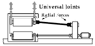
The simple and most common solution to the problem of shaft misalignment is using Double universal joints. The double universal joint coupling consists of two universal joints connected to an common central shaft transmitting power from the input shaft to the output shaft.
Fig1.Radial force transmission by universal
Joint
But the problem with this coupling is that it cause radial forces at the joints, velocity variation, and requires large lateral space.
Problem Solution-The solution to the above problem is an indigenous coupling that gives constant transmission of
IJSER © 2015 http://www.ijser.org
International Journal of Scientific & Engineering Research, Volume 6, Issue 3, March-2015 820
ISSN 2229-5518
torque and angular velocity. The main features of the coupling being;
• Minimize or even eliminate side loads
• Higher shaft misalignment capabilities
• Higher offset capabilities
• Greater drive accuracy.
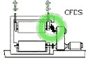
Coupling for displaced shafts offer great flexibility in shaft displacement while maintaining undisturbed power transmission at constant angular velocity. The couplings provide a smooth flow of power for maximum product quality and unlike universal joints, there is no performance loss by increasing shaft offset.
.
Fig.2. Coupling for Displaced Shaft
Shaft couplings-
Component in two halves often flanged. Used to connect two shafts to transmit torque and rotational
motion. To accommodate minor misalignment between the shafts, the torque is usually transmitted by some form of flexible elements
Why a Flexible Coupling?
Connects two shafts, end-to-end in the same line, for two main purposes. The first is to transmit power (torque) from one shaft to the other, causing both to rotate in unison, at the same RPM. The second is to compensate for minor amounts of misalignment and random movement between the two shafts. Belt, chain, gear and clutch drives also transmit power from one shaft to another, but not necessarily at the same RPM and not with the shafts in approximately the same line.
Such compensation is vital because perfect alignment of two shafts is extremely difficult and rarely attained. The coupling will, to varying degrees, minimize the effect of misaligned shafts. Even with very good initial shaft alignment there is often a tendency for the coupled equipment to "drift' from its initial position, thereby causing further misalignment of the shafts. If not properly compensated, minor shaft misalignment can result in unnecessary wear and premature replacement of other system components.
In certain cases, flexible couplings are selected for other protective functions as well. One is to provide a break point between driving and driven shafts that will act as a fuse if a severe torque overload occurs. This assures that the coupling will fail before something more costly breaks elsewhere along the drive train. Another is to dampen torsional (rotational) vibration that occurs naturally in the driving and/or driven equipment. Each type of coupling has some advantage over another type.
There is not one coupling type that can "do it all". There is a trade-off associated with each, not the least of which can be purchase costs. Each design has strengths and weaknesses that must be taken into consideration because they can dramatically impact how well the coupling performs in the application.
Basic Terminology
Angular Misalignment:A measure of the angle between the centerlines of driving and driven shafts, where those centerlines would intersect approximately halfway between the shaft ends. Coupling catalogs will show the maximum angular misalignment tolerable in each coupling. A coupling should not be operated with both angular and parallel misalignment at their maximum values.

Fig.3.Angular misalignment of shaft
A projection or movement along the line of the axis of rotation. Example: Sliding the hub in either direction may change the position of a coupling hub, on its shaft.Thus affecting its axial position on the shaft.

Fig.4. Axial alignment of Shaft
Parallel Misalignment: A measure of the offset distance between the centerlines of driving and driven shafts. Coupling catalogs will show the maximum parallel misalignment tolerable in each coupling. A coupling should not be operated with both parallel and angular misalignment at their maximum values.
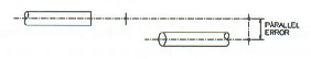
Fig.5. Offset alignment of shaft.(parallel)
LETERATURE REVIEW:
STRAN Technologies, 39 Great Hi l l Road, Nauga t u c k , C T 06770 [1]
When it comes to the design of fiber optic connectors for harsh environments, two schools of thought dominate the market: Butt-Coupled or Expanded Beam Designs. Each approach has its own advantages and disadvantages and the choice of the ‘best’ connector can be blurred by the specifics of the application environment and unique requirements of the systems design. In this white paper, we explain the difference between these two technologies and present the basis of a systems engineering design guide to
IJSER © 2015 http://www.ijser.org
International Journal of Scientific & Engineering Research, Volume 6, Issue 3, March-2015 821
ISSN 2229-5518
assist in the specification of reliable and cost effective fiber optic connectors for harsh environment applications including: Tactical, Shipboard, Aerospace, Geophysical, Railway, Video Broadcast and Power Generation. Key topics of this design guide include: Insertion and Return Loss, Mating Durability, and sensitivity to Thermal and Mechanical extremes.
Lovejoy/Sier-Bath Gear Couplings [2]
Lovejoy offers a variety of designs and models in its gear coupling family. From standard, off-the-shelf stock to new, high speed, special designs, Lovejoy can satisfy your gear coupling needs.
Shaft Alignment White Paper[3]
Despite the best efforts to precisely align rotating machinery shafts, dynamic movement (commonly believed to be due to the thermal growth of the machine casings) has resulted in machines operating at less than optimum alignment conditions. This vexing problem has plagued machine reliability professionals for decades.
Fig.6. Typical Shaft Alignment Tolerances
Irvin Redmond [4]
Misalignment of coupled rotating machinery shafts is a frequently occurring problem which can have a substantial influence on equipment reliability. Experience has shown that diagnosis of misalignment through vibration analysis can be extremely difficult due in large part to the observed substantial variability in the character of machinery vibration even when apparently identical alignment states exist. This paper presents the results of a theoretical study on a simple linear rotodynamicmodel, capable of simulating the effects of parallel and angular misalignment across a flexible-element coupling connecting drive and driven rotors. The model described within has already been developed to enable investigation of interaction of shaft misalignment with mechanical unbalance, non-linear supports and rotating element asymmetry and further work is currently underway to expand the present investigations to assess the influence of these other ‘real world’ rotor dynamic influences.
Greg Towsley [5]
With requirements of organizations to cut costs and manage operation and maintenance budgets better, minimizing equipment downtime has become increasingly important. An aspect of trouble-free operation is the align- ment of rotating equipment. Alignment should be completed on any equipment that has a driver and driven equipment. It should not be standard practice to only align “high energy” or high-speed pumps. ALL pumps should be considered for alignment. To provide an overview of
alignment, the discussion in this article applies primarily to horizontal centrifugal pumps that are operating in a general service and driven by a separate driver through a flexible coupling on a common baseplate. Many of the terms and techniques described can be used for other types of pumps and rotating equipment, but the installation and operation instructions should be followed as required by the manufacturer. This article is meant to be used as a primer only. Extensive training and practice should be completed prior to aligning equipment that is in service.
Fig.7.Impact of Misalignment on Continuous Operating
Life
Mr.Jaiswal. S.B., Prof. Pasarkar M.D. [6]
This paper constitutes the failure analysis of a‘Flange’ that had been welded to a high-water transmissionpipeline. The flange had failed during the operation and thatwas the major point to take care. The analysis was conductedby using ANSYS Workbench 11.0 the integrity of the flange aswell as that of the weld joint. The failure occurred along theweld on the flange side. The flange, which was a havingmaterial as structural steel, was expected to exhibit good weldability. However, the analysis revealed that the structural steelhad a less strengthto allow the pressures. Hence, the newmaterial alloy steel is suggested for the same and around 3iterations are taken on Flange model in ANSYS.
Mr.MaliP. B., Dr.Gawade S. S. [7]
The Five Dimensional Couplings are designed to
accommodate 5 degrees of shaft misalignment. This
coupling allows easy adjustment to any possible
misaligned shaft position without imposing heavy side
loads on shafts, bearings or other machine equipment. Five
Dimensional Couplings offer two parallel misalignments
and three angular misalignments capabilities. The acting
forces within the coupling can be precisely calculated,
assuring a sound coupling design which is especially
important
for heavy-duty applications. If these shaft misalignments
exceed the limit of the selected coupling capacity, excess
side loads are introduced into the equipment which can
cause vibrations, life reduction or failure of vital machine
components such as bearings, motors, etc.
Lung-wen tsai, E.R.maki, R.L.jacques [8]
This paper describe the effectiveness of an Oldham’s coupling type balancer in reducing the first and second harmonic rotating unbalance couple of a 900 even firing engine. It is shown that the prototype balancer can be configured to eliminate the residual, first-harmonic rocking couple usually remaining in a conventionally balanced 900
V6 engine. Further the Oldham’s coupling type balancer
IJSER © 2015 http://www.ijser.org
International Journal of Scientific & Engineering Research, Volume 6, Issue 3, March-2015 822
ISSN 2229-5518
can be used to reduce the elliptical second-harmonic rotating couple to a horizontal rocking couple. The power consumption of the balancer was measured to be approximately 0.35 kw at 2000r/min & 1.5 kw at 4500 r/min.
The Oldham-coupling balancer has been shown to be an effective method for reducing the out-of-balance in a
900 V6 engine. Residual first harmonic out-of-balance can eliminated completely by incorporating counter weighting on the Oldham-coupling main axis. Second harmonic rotating couples can be reduced to minimal horizontal rocking couple that can be isolated by the engine mount.
Summary of Literature Review-By studying all related research papers & Journal it can be concluded that for angular & offset transmission not yet done any analysis on offset coupling having offset 0 to 80 mm. It is necessary to do that by the use of different methodology which gives optimized design parameters.
OBJECTIVE
1. Design & drawing of kinematic linkage to deliver parallel as well angular offset over a range
2. Development & manufacturing of testrig for angular & offset transmission
3. Testing of coupling to derive the performance.
4. Plot Performance Characteristic Curves for
efficiency, Torque, Speed.
5. Kinematic Synthesis of kinematic linkage
mechanism for finding optimized output.
METHODOLOGY Development of Testrig-
A) System Design : This part includes the design and
development for the kinematic linkage as per the geometry to produce the desired output
B) Mechanical Design: This part includes the design
and development of linkages, selection of suitable drive motor , strength analysis of various components under the given system of forces.
Fabrication:
Suitable manufacturing methods will be employed to
fabricate the components and then assemble the test set –
up. The Following part is to be manufactured for test rig.
Part to be Manufactured-
IJSER © 2015 http://www.ijser.org
International Journal of Scientific & Engineering Research, Volume 6, Issue 3, March-2015 823
ISSN 2229-5518
Fig.8.Layout of Test Rig
Procedure for Design & Testing
1. System design as to kinematic design of linkage set to deliver power transmission for parallel offset ( 0 to 80 mm parallel offset on either side of input shaft)
2. System design as to kinematic design of linkage
set to deliver power transmission for angular
offset ( 0 to 5 degree angular offset on either side
of the input shaft )
3. System Design and geometrical derivations of the
control linkage for position of coupling to
achieve vibration free parallel offset to the
desired output in parallel direction of input
shaft.
4. System Design and geometrical derivations of the
control linkage for position of coupling to
achieve vibration free angular offset to the
desired output in angular direction of input
shaft.
5. Selection and design of central link, linkage
geometry for minimum space occupation and
minimum inertia to make drive compact,
lightweight and precise.
6. Selection of motor drive transmission.
7. Mechanical design: This part includes the design
and development of linkages, section dimensions
for strength criterion. The linkage section
dimension will be calculated using theoretical
derivation using appropriate theories of failure
and the dimensions thus arrived to will be
checked and validated using ANSYS.
8. The following components of the drive will be
designed using ANSYS
• Input hub
• Central link
• GE(spherical bearing bush) for central link
• Intermittent parallel offset linkage set
EXPERIMENTAL ANALYSIS Result to be Taken-
1. Testing of drive to derive performance characteristics
a. Torque Vs Speed b. Power Vs Speed
c. Efficiency Vs Speed
d. Maximum parallel offset, and
performance at maximum parallel offset.
e. Maximum angular offset and
performance at maximum angular offset.
2. To check the validity of experimental results with
theoretical results.
3. To carry out comparative study of experimental
and experimental analysis results to decide the
optimization of number of rollers and cam profile.
4. Interpretation of results will be done to suggest the modifications to improve the design of central link profile, parallel linkgeometry , number of
parallel links for desired speed ratio outputs .
Expected Outcome-
Testing: Testing of pump to derive performance characteristics Namely :
• Torque Vs Speed
• Power Vs Speed
• Efficiency Vs Speed
• Maximum parallel offset, and performance at
maximum parallel offset.
• Maximum angular offset and performance at
maximum angular offset.
SCOPE
The following features of the drive will lead to
application of drive in variety of field applications:
• Step-less variation of parallel offset: Any displacement between 0 to 60 mm can be obtained
.Hence the drive provides flexibility in operation and setting as prime mover location can be varies as per space available
• Wide range of angular displacement: The wide range of angular displacement o to 5 degrees enables to get
IJSER © 2015 http://www.ijser.org
International Journal of Scientific & Engineering Research, Volume 6, Issue 3, March-2015 824
ISSN 2229-5518
vibration free power transmission at high speed. This will be especially useful in spring making machinery, textile machinery, printing machinery and automatic transfer lines.
• Compact size: The size of the gear less variable speed reducer is very compact; which makes it low weight and occupies less space in any drive.
• Ease of operation : The changing of parallel and
angular offset is gradual one hence no calculations of
speed ratio required for change gearing .Merely by
rotating hand wheel speed can be changed
• Singular control: Entire range of offset is covered by a
single hand wheel control.
REFERENCES
1. STRAN Technologies, 39 Great Hi ll Road, Nauga tuck , C T 06770 “Expanded Beam versus Butt- Coupled Connectors”, ‘White Paper’ 01-06.
2. Lovejoy/Sier-Bath Gear Couplings “Gear coupling analysis” ,pg. No.1-9, edi-2011
3. Shaft Alignment-A White Paper, STRAN Technologies, 39 Great Hi ll Road, Nauga tuck , C T 06770
4. Irvin Redmond “Shaft Misalignment and Vibration - A Model”, Dynamic Analysis Unit, Consulting Services Department, Saudi Arabian Oil Company, Dhahran 31311, Eastern Province,Saudi Arabia
5. Greg Towsley, “Alignment of angular offset shaft”
-white paper
6. Mr.Jaiswal1S.B.,Prof.Pasarkar M.D. “Failure
Analysis of Flange Coupling In Industry”, ISSN
2250-2459, Volume 2, Issue 5, May 2012.
7. Mr. Mali P. B., Dr.GawadeS. S. “Performance
Investigation of A Five Dimensional Coupling”,
Volume : 3,Issue : 6,June 2014 ISSN - 2250-1991
8. Wen Tsai, Maki E.R., Jacques R.L., Evaluation of
Oldham’s coupling type balancer on 900 v6 Engine
Lung.
IJSER © 2015 http://www.ijser.org