performance of antenna is significantly improved. Improvement in both impedance bandwidth and gain is realized though gain results need further improvement.

International Journal of Scientific & Engineering Research, Volume 5, Issue 12, December-2014 1350
ISSN 2229-5518
A Review on Analysis of Slotted Elliptical
Microstrip Patch Antenna for UWB Applications
Bhumi Bhuva, Vivek Ramamoorthy
—————————— ——————————
.
1 INTRODUCTION
he popularity of wireless communication systems has increased remarkably during the last decade and the market demand still continues to increase. As a vital part of these systems, antenna is one of the most important design issues in modern wireless communication devices. Antennas are designed to operate for specific frequency
bands as they are dependent on frequency.
The antennas must be of low profile, compact size, light- weight, low cost and conformable to the architecture of the mounting devices in wireless communication systems. Among various types of antennas such as log-periodic, Transverse Electromagnetic (TEM) horn, stacked patch, spiral and planar structure, the antenna with planar profile also known as patch antenna, are the most preferred choice. Conventionally, a single antenna cannot operate at all of these frequency bands of mobile communication, numerous different antennas covering these bands separately may be used. However, usage of many antennas is usually limited by the volume and cost constraints of the applications [1].
The recent allocation of the 3.1-10.6 GHz frequency spectrum by the Federal Communications Commission (FCC) for Ultra Wideband (UWB) radio applications has presented a myriad of exciting opportunities and challenges for antenna designers [8]. Conventional patch or microstrip antennas in general have a conducting patch printed on a grounded microwave substrate, and have the attractive features of low profile, light-weight, easy fabrication and conformability to
mounting hosts. Though, microstrip antennas inherently have a narrow bandwidth, which restricts its use in wideband applications. In addition, modern mobile communication systems usually require smaller antenna size in order to meet the miniaturisation requirements of mobile devices. Antenna is an element used for radiating or receiving electromagnetic wave. When available in various different shapes and sizes, they all operate rendering to the principles of electromagnetics. Numerous types of portable electronic devices namely cellular phones, GPS receivers, palm electronic devices, pagers, laptop computers need an effective and efficient antenna for communicating wirelessly with other fixed or mobile communication units. Advances in digital and radio electronics have resulted in the production of a new breed of personal communications equipment posing special problems for antenna designers. A microstrip antenna in its basic configuration has a radiating patch on one side of the dielectric substrate, and a ground plane on the other side. The patch can assume virtually any shape, but regular shapes are generally used to simplify analysis and performance predictions.
2 LITERATURE SURVEY
Several performance evaluations of various elliptical antennas has been done in this section which provides basic details of the elements been reviewed in the paper.
The radiation performance of a modified elliptical patch antenna having three orthogonal sector slots is presented in [2]. It is realized that with the introduction of these sector
IJSER © 2014 http://www.ijser.org
International Journal of Scientific & Engineering Research, Volume 5, Issue 12, December-2014 1351
ISSN 2229-5518
slots, the effective patch size is slightly reduced but the
performance of antenna is significantly improved. Improvement in both impedance bandwidth and gain is realized though gain results need further improvement.
The radiation patterns are still stable and the direction of maximum radiations is directed normal to patch geometry.
Omni-
Omni-
Omni-
Omni- directio
Omni- directio
The meandered ground stubs are introduced to design a
nal
direction
al
directio
n
nal
nal
triple band-notched characteristic for compact planar-
monopole UWB antennas [3]. Studies using computer
simulation and measurement on the return loss, antenna patterns, peak gains and radiation efficiencies of the UWB
2 – 7
dBi
2 dBi 10 dBi
antenna have been carried out. The center frequencies and
bandwidths of the notches can be adjusted using the
FR4
epo
Polytetrafl
uoroethyl
FR4 FR4 FR4
dimensions of the meandered ground stubs. Results have shown that the antenna has approximately omnidirectional
ene
1.33
1.64
1.9 2.5
radiation patterns with good band notched characteristic.
90 % 60 –70
90%
The compact planar elliptical shaped monopole antenna
has been designed with the modified half circular ground
plane [4]. Using two short sleeves on the ground has enhanced the return loss characteristics of the proposed monopole antenna. The simulated results of the proposed antenna have shown wide operating frequency bandwidth from 2.9 GHz up to 16 GHz, while the measured results ranging from 3.1 GHz up to 12 GHz.
A set of elliptic dipole antennas with varying eccentricities have been fabricated for demonstration in [5]. A specific size (specific eccentricity) dipole has successfully yield an impressive 1.5-16 bandwidth beyond the currently available. A couple of elliptic dipole antennas suitable for UWB application have been presented here. This paper also includes the measured swept frequency response, impedance and radiation patterns of all dipoles.
The design and analysis of printed antenna with the reduced ground plane effect, fed by microstrip line for Ultra Wide Band (UWB) communication systems is presented in [7]. The simulated results indicate that the concept of cutting an elliptical patch at radiator has proved to yield a wide operating bandwidth of 2.1-13.8 GHz for -
10dB return loss. Here the main focus is that, the ground-
plane effect on impedance performance is greatly reduced by cutting the patch from the radiator because the electric currents on the ground plane are significantly suppressed at the lower edge operating frequencies.
The table furnished below gives the overview of the parameters of the antenna discussed in the papers been reviewed here.
Table 1. Comparison of parameters
In the paper [2], it is observed that without slot the results getting is narrow bandwidth & lower gain. Also it is concluded that by changing radius and sector angle of the three orthogonal slots, the parameter performances like radiation efficiency, impedance bandwidth and gain has been improved.
Figure 1. Geometry of elliptical microstrip patch antenna with sector slots [2].
In the paper [3], the ground stubs are along the upper edges of the ground plane and feed line is responsible for creating the desired notched bands. Feed line is varied from bottom to top for good impedance matching. Same reason is considered for keeping the gap parameter. Meandered ground stubs are acting like the resonators. When placed at the upper end of ground, it is responsible for preventing the signals from passing through them at resonance. The other stub couples the signal from the feed line to the stub
IJSER © 2014 http://www.ijser.org
International Journal of Scientific & Engineering Research, Volume 5, Issue 12, December-2014 1352
ISSN 2229-5518
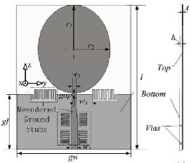
and then flowing to ground through the vias. This prevents the signals from flowing through the feed line into the elliptical radiator and then radiating to free space.
Figure 2. Structure of proposed band notched antenna [3] In the paper [4], the design includes the half modified
ground plane. The design also includes two short I shaped sleeves in the middle which is responsible to enhance the S parameter. The proposed design results in enhancement of the bandwidth as well as improvement in the input return loss. The return loss achieved is better than 10dB which is preferable for better performance of the antenna. It is also observed that as the size of the rectangle ground plane differs it becomes unsuitable to over UWB frequency range perfectly. The parameter H which is the height between the ground and patch also influences the impedance matching of the antenna. The axis ratio is chosen to be 1.64 which performs better in terms of bandwidth. The bandwidth of the antenna largely depends on the sleeve length L i.
Figure 3. Geometry of the modified half circular grounded planar UWB antenna with two sleeves [4]
In the paper [5], a present crescent patch antenna and a bottom fed elliptical antenna is investigated experimentally to provide broadband performance with linear polarization without added complexities inherent in the feed circuit. A set of dipoles with varying axis ratios were etched on the printed-circuit board. The different axis ratios are been examined which had resulted in maximum bandwidth performance in the range of 1.5 to 16 GHz. Hence with the precise choice of axis ratio the operational bandwidth this exceeding the 10:1 ratio. Aside from swept frequency and impedance measurements for elliptic dipoles of various b/a ratios, the radiation patterns for the optimum dipole are measured and found to be in consistency with typical dipole radiation patterns.
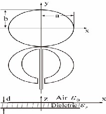
Figure 4. Geometry of an elliptical printed-circuit dipole antenna [5]
This paper [6], a cutting on elliptical patch at the radiator had been designed in this antenna. The simulated results obtained are the return loss (S11) at - 10 dB point & VSWR is less than 2. The bandwidth enhancement techniques are the essential factors in order to obtained return loss starting at 3.1 GHz and end at 10.6 GHz. The antenna has been designed to reduce the ground plane effects by cutting an elliptical patch from the radiator. The patch is able to concentrate the majority of the electric currents on the radiator, especially at lower operating frequencies. The antenna has satisfactory band notched characteristic. The peak value of the VSWR in the stopband from 5 GHz to 6
GHz achieved is 8. The received power obtained here is less in the range of -41 dBm to – 60 dBm when 10 dBm powers is transmitted.
IJSER © 2014 http://www.ijser.org
International Journal of Scientific & Engineering Research, Volume 5, Issue 12, December-2014 1353
ISSN 2229-5518
Figure 5. Geometry of an elliptical dipole antenna [6]
5 CONCLUSION
The microstrip antennas are most preferable antennas having the attractive features of low profile, small size and weight, low cost, printed directly on circuit board and easy to analysis and fabricate.
This paper reviewed the various scenario of slots on the antenna which is responsible for the change in the performance of the antenna. The antennas have been reviewed here are the elliptical patch antenna which are proved to give the better performance for Ultrawideband applications.
6 REFERENCES
[1]. Balanis C. A, “Microstrip Antennas”, Antenna Theory, Analysis and Design, Third Edition, John Wiley & Sons, pp-811-876, 2010.
[2]. Vijay Sharma, V. K. Saxena, K. B. Sharma and Deepak Bhatnagar, “Radiation Performance of an Elliptical Patch Antenna with Three Orthogonal Sector Slots”, Romanian Journal of Information Science and Technology, Volume 14, No. 2, 2011.
[3]. Weng YF, Cheung SW, Yuk TI, “Triple band-notched
UWB antenna using meandered ground stubs”, The
2010 Loughborough Antennas and Propagation
Conference (LAPC 2010), Loughborough, U.K., 8-9
November 2010.
[4]. Ashraf A. Adam, Sharul Kamal Abdul Rahim, Kim
Geok Tan and Ahmed Wasif Reza, “Design of 3.1–12
GHz Printed Elliptical Disc Monopole Antenna with Half Circular Modified Ground Plane for UWB Application”, Wireless Pers Communication (2013), Springer 2012.
[5]. Chunchi Lee, Hsinsheng Huang, Chengda Yang and Chiawei Wang, “An Experimental Study of the Printed-Circuit EllipticDipole Antenna with 1.5-16
GHz Bandwidth”, I. J. Communications, Network and
System Sciences, 4, 285-385, 2008.
[6]. Abhishek Katariya, Heena Gupta and K. K. Prajapat, “An Elliptical Patch UWB Antenna with Reduced Ground Plane Effect”, 2011 International Conference on Computational Intelligence and Communication Systems, IEEE, 2011.
[7]. W. Mazhar, M. A. Tarar, F. A. Tahir, Shan Ullah and F.
A. Bhatti, “Compact Microstrip Patch Antenna for
Ultra-wideband Applications”, PIERS Proceedings,
Stockholm, Sweden, Aug. 12-15, 2013.
[8]. Johnna Powell and Anantha Chandrakasan, “Differential and Single Ended Elliptical Antennas for
3.1-10.6 GHz Ultra Wideband Communication”, IEEE,
2004.
[9]. H. Schantz, “A Brief History of UWB Antennas”, IEEE UWBST, 2003.
[10]. K.Siwiak and D. McKeown, “Ultra-Wideband Radio
Technology”, Wiley UK, 2004.
[11]. H. Schantz, “Planar Elliptical Element Ultra-Wideband
Dipole Antennas,” IEEE APS 2002.
IJSER © 2014 http://www.ijser.org