International Journal of Scientific & Engineering Research, Volume 5, Issue 6, June-2014 13
ISSN 2229-5518
A New Microstrip Bandpass Filter Design
Based on Slotted Patch Resonator
Yaqeen S.Mezaal 1, Ali N.Nasret 1,2
1Electronic and Communication Engineering Department, Cankaya University , Ankara, Turkey
2Electrical Engineering Department , Al-Mustansiriya University,Baghdad ,Iraq
Email : yakeen_sbah@yahoo.com, ali_hjk2000@yahoo.com
Abstract— A narrowband, compact, and flexible fabricated microstrip bandpass filter design is presented in this paper as a aspirant for us e in modern wireless systems. The proposed filter design is based on the use of dual-mode (two pole) microstrip patch resonator with uniform geometrical slot. This filter has the advantages of owning much narrower and sharper performance responses as compared to single mode resonator and other conventional square patch filters. The performance of filter structures, based on dual-mode resonators, has been evaluated using Sonnet electromagnetic simulator . This filter has been designed at resonant frequency 4.16 GHz using a substrate with a dielectric constant of 10.8 and thickness of 1.27mm.Performance simulation results show that filter structure offers very good frequency
responses in addition to narrow bands gained , compactness properties and 2nd harmonic suppression in out of band region.
Keywords — Dual mode filter, microstrip bandpass filter , slotted patch resonator, 2nd harmonic suppression
1 INTRODUCTION
—————————— ——————————
Emerging wireless applications require versatile systems with multifunctional and multi-band characteristics. In recent years, RF and microwave filters have undergone a natural evolution by adding tunability to their passive functions. A microstrip bandpass filters can be easily mounted and the circuit layout design can be more flexible [1,2]. The dual-mode resonators filters are known for years. The compact high performance microwave bandpass filters are highly desirable in the wireless communications systems. Thus, the dual-mode filters have been used widely for these systems because of their advantages such as small size, light weight, low loss and high selectivity. Many wide-band bandpass filters have been proposed using dual-mode ring resonators with tuning stubs but the configurations of these filters still occupy a large circuit area, which is not suitable for wireless communication systems where the miniaturization is
an important factor [2][3]. Therefore, it is desirable to develop
new types of dual-mode microstrip resonators not only for
offering alternative designs, but also for miniaturizing filters. On the other hand, the modern wireless communication systems require the bandpass filters having effective out-of- band spurious rejection and good in-band performance. Therefore, the resonators are widely used in design of antennas [4] and filters [5,6]. Microstrip bandpass filters have been widely used in a variety of microwave circuits and systems. Recently, the dual-mode concept means two degenerate modes of a geometrically symmetrical resonator, and its main feature and advantage is that each dual-mode resonator can be used as a doubly tuned resonant circuit, which leads to a compact filter configuration. For dual mode
operation, a perturbation with an asymmetrical supply line resonator element or an exciting two degenerate resonant modes must be introduced to split and double.
Microstrip dual-mode bandpass filter may be square patch, triangular patch, rectangular patch and their ring patches[3,5,6,7,8,9], and can be fabricated by direct coupling without coupling gaps.
In this paper,dual mode microstrip slotted patch bandpass filter with narrow band response and adequate performance has been presented. The proposed filter has no trend to support 2nd harmonic which is commonly appeared in filter designs.
2 DUAL MODE FILTER DESIGN
Dual-mode resonators have been widely used to realize many RF/microwave filters [9,10]. A major feature and interest of this type of resonator lies indeed that each of dual-mode resonators can used as a doubly tuned resonant circuit, and moreover the number of resonators required for a n-degree filter is decrease by half, resulting in a compact filter arrangement.
A microstrip dual-mode resonator is not necessarily square in
shape, but usually has a two-dimensional (2-D) symmetry.
Figure 1 shows some typical microstrip dual-mode resonators, where D above each resonator indicates its
symmetrical dimension, and 𝜆𝑔𝑜 is the guided-wavelength at
its fundamental resonant frequency in the associated
resonator. Note that a small perturbation has been applied to
IJSER © 2014 http://www.ijser.org
International Journal of Scientific & Engineering Research, Volume 5, Issue 6, June-2014 14
ISSN 2229-5518
each dual-mode resonator at a location that is assumed at a
45° offset from its two orthogonal modes. For instance, a
small notch or a small cut is used to disturb the disk and square patch resonators, while a small patch is added to the ring, square loop, and meander loop resonators, respectively. It should be mentioned that for coupling of the orthogonal modes, the perturbations could also take forms other than those demonstrated in Figure1. For example, a small elliptical deformation of a circular patch or disk may be used for coupling the two degenerate modes and, similarly, a square patch may be distorted slightly into a rectangular shape for the coupling.
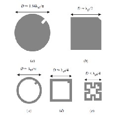
Figure 1 Some microstrip dual-mode resonators. (a) Circular disk. (b) Square patch. (c) Circular ring. (d) Square loop. (e) Meander loop.
In this study, a dual-mode microstrip patch bandpass filter structures have been designed at frequency of 4.16 GHz as in Figure 2. It has been supposed that this filter structure has been etched using a substrate with a dielectric constant of 10.8 and thickness of 1.27 mm.Two 50 ohm feed lines as input and output (I/O) ports are placed in orthogonal manner . Accordingly, the side length of the square slotted patch resonator, L = 9 mm, has been determined as:
mm. Also, the values of X,Y,Q and S are 3 mm ,2 mm ,1 mm and 0.6 mm respectively .
Figure 2 The layout of the modeled dual-mode slotted patch
BPF
The slot form of the proposed patch resonator acts as some perturbation effects to the symmetry of the structure, therefore the field distributions of the degenerate mode will be no longer orthogonal, and they are coupled to each other [11].
The dual-mode bandpass filter response can be obtained via
the excitation of the two degenerate modes by input/output feeders and setting the coupling between the two modes by inserting suitable form of perturbation effect within the resonators [11].
The dimensions of the perturbations of each filter must be
tuned for the required filter performance, since the nature and the strength of the coupling between the two degenerate modes of the dual-mode resonator are mainly determined by the perturbation’s size and shape. However, extensive details about this subject can be found in [3,10].
.
where
L = 0.3λg 0
(1)
3 PERFORMANCE EVALUATION
A dual-mode filter construction based on slotted square patch resonator has been modeled and examined using a
λg 0 =
f

c
ε eff
(2)
full-wave based electromagnetic simulator from Sonnet Software Inc.This simulator carries out electromagnetic investigation using a modified approach of method of
is the guided wavelength, ε eff
≈ (ε r + 1) / 2 , and c is the
moments (MoM). The filter structure is shown in Figure 2 . The consequent simulation result of return loss and
speed of light,
ε eff is effective dielectric constant and ε r is
transmission responses of this filter is shown in Figure 3 .
relative dielectric constant [9,10]. By the way, the
perturbation square patch side length (d) is 0.8 mm while the
gap between I/O feeders and slotted patch resonator is 0.2
It is implied from Figure 3 that the resulting bandpass filter offers agreeable return and transmission responses. Also, the output response has no tendency to support 2nd harmonic that usually accompanies the bandpass filter performance.
IJSER © 2014 http://www.ijser.org
International Journal of Scientific & Engineering Research, Volume 5, Issue 6, June-2014 15
ISSN 2229-5518
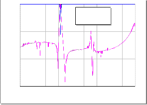
TABLE I shows the results of the modeled filter dimensions as designed for 4.16 GHz application with corresponding filter performance parameters. This filter has narrow band frequency response which is usually a key objective in telecommunication systems in order to make the filter able to reject the interference of strong signals operating in the adjacent bands .
0
S11 S21
is in quasi elliptic response case. The previous filter size design can be altered to other frequencies involved for other wireless communication systems. In this case, the resulting new filter will be larger or lower in size in accordance with the frequency constraints of the specified applications.
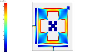
The surface current density Simulation results at 4.16 GHz and 4.5 GHz are represented in Figures 5 and 6 respectively. In these figures, the red color points to the maximum
coupling effect while the blue color signifies the minimum
-10
-20
-30
-40
-50
-60
1 2 3 4 5 6 7 8 9 10
Frequency (GHz)
one.The maximum surface current densities can be seen at the design frequency, which is straightforward from the fact that low losses are present and the desired resonant frequency is within higher excitation condition. On the contrary, the lowest current densities can be noticed at 4.5 GHz in stopband region . In this case, weakest coupling can be seen, which is given by the fact that the designed filter is not being excited and, therefore, provides a strong rejection in an otherwise passband structure. For 4.16 design cases, we can see from Figure 7 that increasing d, the side length of small perturbation square patch at the right top corner, causes S21 first to move rapidly upward toward the ideal 0dB point and
Figure 3 Return loss, S11 , and transmission, S21 , responses for microstrip bandpass filter shown in Figure 2
then split into two visible peaks. Ideally there would be no coupling between the two modes at d = 0 mm.
TABLE I Summary of the calculated and simulation results of the modeled filters
200
100
S11 (Deg) S21 (Deg)
0
-100
-200
1 3 5 7 9 10
Frequency (GHz)
Figure 4 shows the non-linear phase response for S11 and S12 with respect to different frequencies. This phase response includes some frequency jumps which are the significant properties of quasi elliptic BPFs.
The use of uniform geometrical slot in conventional patch lessens their fundamental frequency. This is due to the application of surface geometrical cuts which increase the current path length, produce a decrease or shifting in the resonance frequency without altering the external dimensions.
Results show that the modeled bandpass filters possess good performance curves. As can be seen, the filter response
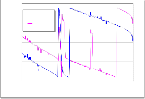
Figure 4. The phase responses of proposed slotted patch BPF
IJSER © 2014 http://www.ijser.org
International Journal of Scientific & Engineering Research, Volume 5, Issue 6, June-2014 16
ISSN 2229-5518
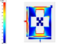
Figure 5 Simulated current density distributions of the proposed BPF at 4.16 GHz
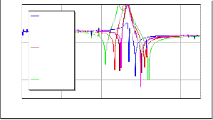
Figure 6 Simulated current density distributions of the proposed BPF at 4.5 GHz
0
d=0 mm
[3] Yaqeen S. Mezaal and Halil Tanyer Eyyuboglu, “A new narrow band dual- mode microstrip slotted patch bandpass filter design based on fractal geometry,”
7th International Conference on Computing and Convergence Technology
(ICCCT), pp.1180-1184, 2012.
[4]H.Iwasaki , A Circularly Polarized Small-Size Microstrip Antenna with a
Cross Slot, IEEE Trans Antennas Propagation., vo1.44, 1996.
[5] J. Xiao, S. Li and Y. Li , Novel Planar Bandpass Filters Using Single Patch
Resonators with Corner Cuts, Journal of Electromagnetic Waves and
Applications, Vol.20, No.11, pp. 1481-1493, 2006.
[6] X. Wang, W. Ji, and Y. Li, Microstrip Bandpass Filter Using One Single
Patch Resonator with Two Transmission Zeros, Electron Lett., vol.39, no.17, pp.
1255-1256, 2003.
[7] J.S. Hong and M.J. Lancaster, Bandpass Characteristics of New Dual-Mode
Microstrip Square Loop Resonators, Electronics Letters, vol.31, no.11, pp.891-
892, 1995.
[8] J. Chen and Q. Xue , Novel Microstrip Bandpass Filter Using One Equilateral
Triangular-Patch Resonator, Microwave Opt Technol. Lett., Vol.44, pp.222-
223,2005.
[9] K. Chang, and L. Hsieh, Microwave Ring Circuits and Related Structures,2nd
Edition, John Wiley and Sons Ltd., 2004.
[10] J.S. Hong, and M.J. Lancaster, Microstrip Filters for RF/Microwave
Application, New York, Wiley, 2001.
[11] E.S. Ahmed, “Dual-Mode Dual-Band Microstrip Bandpass FilterBased
on Fourth Iteration T-Square Fractal and Shorting Pin”,radio engineering journal,vol.1 , no.2, June 2012.
-20
d=0.6 mm
-40

d=0.8 mm
-60 d=1.2 mm
-80
d=1.6 mm
-100
1.5 2.5 3.5 4.5 5.5 6
Frequency (GHz)
Yaqeen Sabah Mezaal was born in Baghdad, Iraq, in
1985. He received the B.Sc. degree in Electronic and Communication
Engineering from University of technology, Baghdad, Iraq in 2007, the M.Sc.
degree from the same university in 2009.He is currently PhD researcher of
Figure 7 Simulated transmission responses, S21, of proposed
BPF as a function of d in units of mm for the case of 4.16 GHz
4 CONCLUSION
In this paper, a new narrow dual-mode bandpass filter has been presented as a new technique for modern wireless communication systems. In this technique, dual-mode bandpass filter structures have been generated by applying uniform slot on conventional dual-mode square patch resonator.
The modeling and performance of proposed filters have been evaluated using a full-wave based electromagnetic sonnet simulator with a dielectric constant of 10.8 and thickness of 1.27mm at 4.16 GHz resonant frequency .The proposed filter has good S11 and S21 responses, also, the out of band doesn’t enhance 2nd harmonic frequency order which is very requested property for filter performance.
5 REFERENCES
[1] J.S. Hong and M.J. Lancaster ,Microstrip Filters for RF/Microwave [1] C. Lugo and J. Papapolymerou , Bandpass Filter Design using a Microstrip Triangular Resonator with Dual-Mode Operation. IEEE Trans Microwave and Wireless Components Lett., vol. 15, pp.475-477, 2005.
[2] J.S. Hong and S. Li , Dual-Mode Microstrip Triangular Patch Resonators and
filters. IEEE MTT-S Dig., pp. l901-1904, 2003.
Electronic and Communication Engineering at Cankaya University, Ankara, Turkey. He had More than 12 papers in international and local conferences and peer reviewed journals. His research interests include wireless communication and microwave circuits design. Mr.Yaqeen has good experience in engineering software relating to the electronic and communication applications such as Matlab, Microwave Office, from Advanced Wave Research Inc., and Sonnet Software Inc .He is Member of IEEE.
 Ali Najdet Nasret was born in baghdad , in 1985. He received the B.Sc. degree in Electrical Engineering from University of Mustansiriya Baghdad, Iraq in 2010. He is currently M.Sc. researcher of Electronic and Communication Engineering at Cankaya University, Ankara, Turkey . His research interests include wireless communication and microstrip filter designs.
IJSER © 2014 http://www.ijser.org