Inte rnatio nal Jo urnal o f Sc ie ntific & Eng inee ring Re se arc h, Vo lume 3, Issue 2, February -2012 1
ISS N 2229-5518
A Low Cost Surface Electromyogram (sEMG) Signal Guided Automated Wheel Chair for the Disabled
Taslim Reza, S.M.Ferdous, Md. Nayeemul Hasan, Md. Rokonuzzaman, Kazi Firoz Ahmed, A.Z.M.Shahriar Muttalib
Abs tract— This paper discusses the exploratory research of a simple, ef f ective and low cost design of a microcontroller based w heelchair using the sEMG signal collected f rom the neck muscles w hich w ill allow a disabled person to co ntrol the w heelchair only by using the movement of his neck. Among the diff erent neck muscles, upper trapezius muscle has been chosen f or collection of the sEMG signals w hich are used to move, control and navigate the w heel chair . The main purpose of the w ork is to design a cost-effective, easily aff ordable and accessible w heel chair f or the disabled general masses w here advanced attachments like on board computer, d igital ca meras , sophisticated sensors etc. are not being used, rather concentration has been paid on designing a more practical and simple but eff ective system using an electrically controlled diff erential drive w ith only tw o w heels .
Inde x Terms— Automated Wheel Chair, Bio- Electric Amplif ier, Dif f erential Drive controller, F/V converter, Myoelectric Signal processing, PID control, sEMG signal.
—————————— ——————————
ver the years, the neur ophysiology and biomechanics of muscle systems have been investigated quite extensively based on the r esearch of sur face EMG signal. Sur face
Electr omyogr aphy (EMG) signals r epr esent the electr ical activ- ity of a muscle dur ing contr action [1]. The sur face EMG sig- nals ar e complex and non stationary time sequence that can be consider ed as dir ect r eflection of the muscle activity [2]. In this wor k EMG signals collected fr om the muscles r esponsible for two types of movements of neck medically termed as – flexion (the movement in which the chin is low er ed down toward the chest ) and lateral rotation (r otation to the left or to the r ight towards the shoulder ); ar e used as the contr olling signal for the wheelchair movement. In the past decade, a number of simple yet effective hands-fr ee human machine inter faces (HMI) ar e br ought into applications using human physiologi- cal signals such as electr omyography (EMG), electr ooculogra- phy (EOG) and electr o-encephalography (EEG).
———— ——— ——— ——— ———
Taslim Reza has obtained his Masters degree in Biomedical Engineering from Tamper University, Finland and Bachelor degree in Electrical and Electronic Engg from Islamic University of Technology, Bangladesh. Currently he is serving as Lecturer in Dept. of EEE of American Interna- tional University of Bangladesh (AIUB), Dhaka, Bangladesh.
S.M.Ferdous has obtained his Masters and Bachelor degree in Electrical
and Electronic Engg from Islamic University of Technology, Bangladesh.
Currently he is serving as Lecturer in Dept. of EEE of American Interna-
tional University of Bangladesh (AIUB), Dhaka, Bangladesh.
Md. Nayeemul Hasan is currently serving as Lecturer in Dept. of EEE
of American International University of Bangladesh (AIUB), Dhaka,
Bangladesh. E-mail: nayeem01@yahoo.com
Md. Rokonuzzaman is currently serving as Lecturer in Dept. of EEE of
University of Asia Pacific (UAP), Dhaka, Bangladesh.
Kazi Firoz Ahmed is currently serving as Lecturer in Dept. of EEE of
American International University of Bangladesh (AIUB), Dhaka,
Bangladesh. E-mail: k.firoz@aiub.edu
A.Z.M Shahriar Muttalib is currently serving as Lecturer in Dept. of
EEE of American International University of Bangladesh (AIUB),
Dhaka, Bangladesh. E-mail: sadi_eece@yahoo.com
As can be seen in liter atur e [1, 2], HMIs developed fr om these signals ar e used for hands-fr ee contr ol of electr ic-power ed Wheelchairs. Li and Tan [3] pr opose a bimodal wheelchair contr ol appr oach by integrating vision and speech contr ols. Matsumoto and Ino et al. [4] apply the r ecognition of head motion and eye gaze onto a locomotive wheelchair system. Ferr eira and Silva et al. [5] pr oposed an HMI str uctur e to con- tr ol a r obotic wheelchair by scalp EMG and EEG signals.
This paper presents a solution for those kinds of disabled
people who are unable to spend a lot of money to buy a fancy wheelchair that requires on board computer and other expen- sive instruments. A simple structure and user friendly control system are used to control the wheelchair movement using only the movements of neck muscles. Generally this type of design would suit most to the people those who are totally disabled, that means completely unable to move their hand or leg. First part of the paper shows the extraction of EOG signal by elaborately analyzing the anatomy of the eye muscles and processing of those signals to make it compatible to use in con- junction with a microcontroller. Second part shows the stru c- ture and control mechanism of the wheelchair.
Myoelectric signals or surface electromyograms (sEMG) are produced during muscle contraction when ions flow in and out of muscle cells. When a nerve sends the signal to initiate muscle contraction a potential is developed across the muscle due to the movements of electrolytes. This ionic current can be converted into electronic current with Ag-AgCl electrodes placed on the surface of the skin of the contracting muscle. A typical EMG signal has an amplitude level of 0-5mV with a frequency range of 0-500Hz where the dominating frequency lies in the range of 50-150 Hz.
IJSER © 2012
Inte rnatio nal Jo urnal o f Sc ie ntific & Eng inee ring Re se arc h, Vo lume 3, Issue 2, February -2012 2
ISS N 2229-5518
Ther e total thr ee electr odes placed on the differ ent muscles as shown in Fig.1(a). For signal acquisition the upper trapezius muscle is chosen wher e tw o electr odes – R (right) and L (left) have been placed. To obtain a r efer ence point (the point w ith r espect to that the potentials ar e being measur ed) a thir d electr ode is placed at point G. Any movement of the muscle
specially contraction will generate an EMG signa l as shown in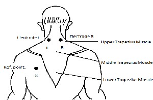
Fig. 1(b), which can be sensed and acquir ed thr ough elec- tr odes.
Fig. 1(a). Placement of electrodes on diff erent points of neck muscle f or signal acquisition.
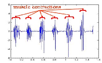
Fig. 1(b).Generation of sEMG signals w hen muscles are contracted.
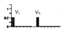
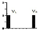
For navigating the wheel chair two types of rotation of neck muscle are considered- Flexion and Lateral rotation. From these movements four types of movement should be identified to control the motor. It has been observed that, different move- ments of trapezius muscle can produce voltages with different levels [6]. These are shown graphically with the help of fol- lowing diagrams of Fig.2. [6].
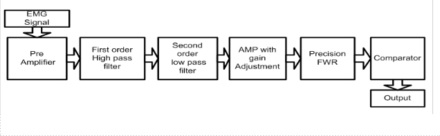
A signal acquisition model is developed to acquire the sEMG signal due to the movement of head. Acquired signals are processed, filtered and amplified to feed to a microcontroller which in turn will produce the necessary driving pulses of the motors to navigate the wheel chair. The functional blocks of the acquisition module and steps are shown in Fig. 3.
(a) Head at rest
(b) Head Flexion to 45º
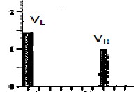
(c) rotation of the head to the lef t
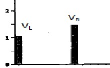
(d) rotation of the head to the right
Fig. 2. Measured sEMG signal f or trapezius muscles during diff erent movements of the head. VL and VR are the lef t and right electrode voltage respectively, plotted in logarithmic scale.
For Ref erence, 2 = log10 (100µV) [6]
With exactly same process two identical acquisition modules are used to collect signals from the neck muscles. Generally the noise components are in the frequency range of 0 -10 Hz (low frequency motion artifacts) and 500+ Hz (movement be- tween electrodes and skin surface). By using a HPF and a LPF
unwanted noises are filtered out. A 0-5V input is required for
operation of a microcontroller and hence a precision rectifier along with an amplifier with adjustable gain is introduced to convert the bipolar sEMG into unipolar signal. At the final
IJSER © 2012
Inte rnatio nal Jo urnal o f Sc ie ntific & Eng inee ring Re se arc h, Vo lume 3, Issue 2, February -2012 3
ISS N 2229-5518
Fig. 3. Steps and components of EMG signal Acquisition.
stage, a comparator with a threshold voltage level of 3V is used to clearly distinguished between the two different head movements as both the electrode (right/left) would produce some voltages during lateral rotation. But the muscle of a par- ticular side will be more contracted if it is the side at which the head has been moved, and then the voltage generated by the electrode of that side would be higher compare to the other one. Hence the comparator will produce an output volta ge high if the corresponding electrode along with its amplifier generates a voltage greater than that. The circuit arrangements of the module and final acquired signal after processing are shown in Fig.4 and Fig.5 respectively.
The system is capable of producing three movements - forward motion, left and right rotation. The wheelchair employs a di f- ferential drive system where the motion controller converts motor rotations into useful torques which are in turn mapped to wheel velocities. The differential drives used have two in- dependent drive wheels on the left and right sides, enabling the chair to move at any desired directions. Casters on the front or back or both ends keep the chair level.
The layout of the chair showing all the components are shown in Fig.6. Two 12V, 5A (60W) PMDC motor is used to drive the wheelchair where the motors are connected with a Bevel gear arrangement which are finally connected with the axis of the wheel.
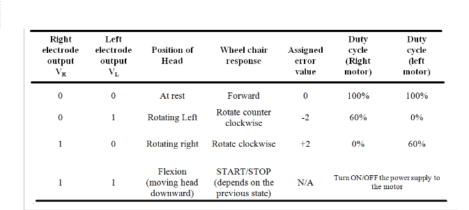
Control for the two motors in the system is carried out by us- ing an H- bridge motor controller. The driving signals are generated by the microcontroller which produces appropriate PWM signals for appropriate movement of the chair. Depen d- ing on the direction of movement of the head, the associated neck muscle will force the corresponding electrode output to go high.
The complete movement of the motor depending on the movement of the head is summarized in Table.1. A simple but effective algorithm is developed and implemented using the microcontroller. Depending on the control algorithm the duty cycle of a particular motor is varied to obtain the desired
response from the system.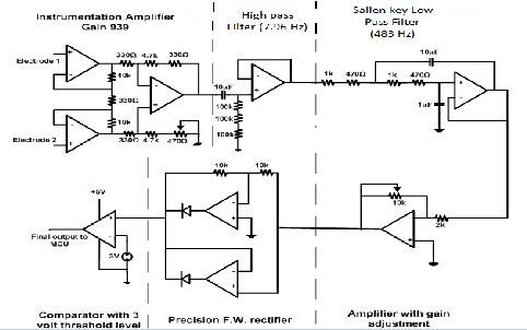
Fig. 4. Co mplete Circuit Diagram of EMG Signa l Acquisition and Processing Unit (Bio-electric Amplif ier)
IJSER © 2012
Inte rnatio nal Jo urnal o f Sc ie ntific & Eng inee ring Re se arc h, Vo lume 3, Issue 2, February -2012 4
ISS N 2229-5518
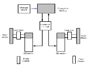
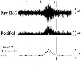
Fig. 5. Detected sEMG Output Signa l.
Based on the algorithm, next the controller is developed using the microcontroller. The control structure of the wh eel chair is modeled in Fig. 7. To obtain a smooth and fast response a PID controller is applied in the system. The error signal, e1 is gen- erated depending on the direction of movement and is as- signed with a value enlisted in Table.1. Next the value is com- pared with a pre-assigned reference value which in turn will generate the necessary duty-cycle for the PWM signals.
Duty-cycles are generated by following the equations [eq. (4) -
eq. (7)]. The PWM signal will operate a motor controller IC which will furnish sufficient amount of current and voltage from the power supply to run the motor.
Fig. 6. Layout Design of the Wheel Chair
The reference voltages are set as follows -
Vref = 5 ……………………………………... (1) VR = Vref + e1………………………………... (2)
VL = Vref - e1.................................................... (3)
For Right Motor (to rotate CW/ right)
Duty Cycle, DCR = 20VR ; for 0 ≤ VR < 5....(4) Duty Cycle, DCR = 0 ; for VR ≥ 5......... (5)
For left Motor (to rotate CCW/ left)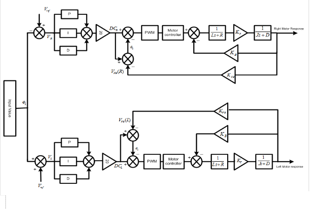
Duty Cycle, DCL = 20VL ; for 0 ≤ VL < 5.....(6) Duty Cycle, DCL = 0 ; for VL ≥ 5.......... (7)
Fig. 7. Block Diagram Representation of the Wheel Chair Control System
IJSER © 2012
Inte rnatio nal Jo urnal o f Sc ie ntific & Eng inee ring Re se arc h, Vo lume 3, Issue 2, February -2012 5
ISS N 2229-5518
TABLE 1
UNIT S CONT ROL ALGORIT HM FOR THE MOVEMENT OF THE MOT OR
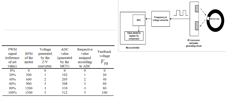
Feedback is employed to ensure accuracy of the system d e- signing a closed loop controller. Depending on the set value the motor will run at a particular speed. The speed of the mo- tor is sensed by an Infra red transmitter- receiver and a pulse generating circuit. These pulses are sent to a frequency to vol- tage converter which is calibrated to produce 5 volts when the input signal has a frequency of 25 Hz (i.e. 25 pulses per second). The output voltage of an F/V converter is fed to mi- crocontroller where it is sampled and stored using Analog to Digital converter. The Feedback signal, VFB is then generated using the following equation implemented by the MCU.
VFB = (25/ 128) x (ADC value).................. (8)
The total process of feedback signal acquisition is enlisted in
Table 2.
To obtain a closed loop controller, a Feebback signal is needed to be generated and fed to the Microcontroller via the ADC port. A reflective tape can be placed on the rotating part of the motor or the shaft to count the RPM of the motor and through generated electrical pulses. These pulses can be fed to a Frequency to voltage converter circuit to generate a voltage proportional to the speed of the mo tor. Later on the generated voltage can be fed to the ADC port and processed accordingly to produce necessary feebback signal, VFB for comparision and generation of error value. The total system can be represented with the help of a block diagram shown in Fig. 8.
TABLE 2
FEEDBACK SIGNAL ACQUISITION AND GENERAT ION OF VFB
Fig. 8. Block Diagram Representation of Feedback Signal Acquisition
The design of the wheel chair along with its simple but effec- tive algorithm suggests that, it can be a very good method to obtain system assisted mobility for the disabled. The accuracy and performance of the system depends greatly on the signal acquisition. So, the signal acquisition and processing module should be designed with great care. The simplicity of the sys- tem makes it a perfect candidate for practical implementation. In spite of its effectiveness still there is a lot of room for i m- provements. Intelligent control system like neuro-fuzzy con- troller, adaptive control may be introduced in the system to obtain a better performance from the system and make the
IJSER © 2012
Inte rnatio nal Jo urnal o f Sc ie ntific & Eng inee ring Re se arc h, Vo lume 3, Issue 2, February -2012 6
ISS N 2229-5518
system more versatile, dynamic and fast.
The authors wish to thank Mr. Ahmed Mortuza Saleque, Lec- turer of EEE Department in American International Univers i- ty- Bangladesh (AIUB), for his valuable suggestions and cor- dial support during the entire time period of this Project Work.
[1] Made le ine M. Lo we ry , Nikolay S . Stoykov, Allen Taflove, Todd A.Kuike n, “ A Multiple -lay e r Finite Ele me nt Mo de l o f the S urface EMG S ig nal, “IEEE Transac tio no n Bio me dic al Eng inee ring , vo l 49, no .5, May 2002, pp446 -456.
[2] Re se arc h o n the S urface EMG S ig nal fo r Human Bo dy Mo tio n Re-
cog nizing Base d o n Arm Wre stling Ro bo t ; 12Zhe n Gao, 1" 2Jianhe
Le i, 1" 2Quanjun So ng , ' Yo ng Yu, ' YunJian Ge; Procee ding s o f the
2006 IEEE Inte rnatio nal Co nfe re nce o n Info rmatio n Acquisitio n A u-
g ust 20 - 23, 2006, We ihai, S hando ng , China.
[3] Moo n, I., Lee , M., Chu, J., Mun, M.: We arable EMG -base d HCI fo r
e lec tric -po we re d whee lc hair use rs with mo to r disabilitie s. In: Pro-
cee dings o f IEEE Inte rnatio nal Co nfe re nce o n Robo tics and Auto ma- tio n, pp. 2649–2654 (2005).
[4] Bare a, R., Boque te , L., Mazo , M., Lo pe z, E.: Syste m fo r assiste d mo bil- ity using eye move me nts base d o n e lec trooc ulog raphy . IEEE Trans- ac tio ns o n Ne ural Syste ms and Re habilitatio n Eng inee ring 10, 209–
218 (2002)
[5] Tsui, C.S.L., Jia, P., Gan, J.Q., Hu, H., Yuan, K.: EMG -base d hands-
fre e whe e lc hair co ntro l with EOG atte ntio n shift de te c tio n. In: Pro-
cee dings o f IEEE Inte rnatio nal Co nfe re nce o n Ro bo tics and Bio mi- me tics, pp. 1266–1271 (Dece mbe r 2007)
[6] V. Regg ie Edge rto n, S tev e n L. Wo lf, Danie l J. Leve ndo wski, Robe rt I.
Je nnric h, Ro land R. Roy , “EMG Ac tiv ity in Neck and Bac k Musc le s
During Se lec te d S tatic Posture s in Adult male s and Fe male s”, Phy sio-
the rapy Theo ry and Prac tice (1997) 13, 179 -195.
[7] Mo hammad Ro ko nuzzaman, S .M.Fe rdo us, Rashe dul Amin Tuhin,
S abbir Ibn Arman, Tasnim Manzar, Md. Nayee mul Hasan. “Desig n
o f an Auto no mo us Mo bile Whee l Chair fo r Disable d Using Elec troo-
c ulog ram (EOG) Sig nals.”, DOI : 10.1007/978 -3-642-23244-2_6, Me-
c hatro nics-Rece nt Tec hno log ic al and Sc ie ntific Adv ance s, Ry szard
Jablo ński, To maš Březina (Edito rs), Publishe d by S pringe r Be rlin
He ide lbe rg , ISBN- 978-3-642-23243-5 (Print) , 978-3-642-23244-2 (On- line ), DOI- 10.1007/978-3-642-23244-2, S pring e r Public atio n Date -
S aturday , Se pte mbe r 24, 2011.
IJSER © 2012