International Journal of Scientific & Engineering Research Volume 4, Issue 1, January-2013 1
ISSN 2229-5518
A Connected E-Shape and U-Shape Dual-Band Patch Antenna for Different Wireless Applications
Md. Mahabub Alam1 , Md. Suaibur Rahman2
Abstract—In this paper, dual operation E-shape and U-shape Patch Antenna feed by transmission line is presented and study the effect of antenna dimensions length (L), width (W ) and substrate parameters relative dielectric constant(Er), substrate thickness on radiation pa- rameters of Band width. The proposed antenna is designed on two-layer, one RT/Duroid 6006 laminate substrate and another ground plane with an area of 33 mm by 42 mm. This paper contains designing a Connected E-Shape and U-Shape Dual Band Patch Antenna for different wireless applications except for its narrow band width. The dual operation frequencies are 2.46 GHz and 4.9 GHz. A (-8 dB) bandwidths of return loss S characteristic for the dual band are 13.02 % and 3.28 % respectively. This connected U-shape & E-shape patch antenna is mainly applicable to wireless local area net-works (WLAN).This paper suggests an alternative approach in enhancing the band width of microstrip antenna for the wireless application operating at a dual frequencies 2.46 GHz and 4.9 GHz. The measured results have been compared with the simulated results using software GEMS version-7.0.
Index Terms— E-shape, U-shape, Dual-Band, Patch Antenna, W LAN, Radiation pattern, Laminate, Bandwidth.
—————————— ——————————
tucture of U-shape & E-shape Design microstrip patch antennas have been developed in the past for broadband applications, including 2GHz wireless communication sys- tems[1][2].Recently, authors investigated the application of the connected U-shape & E-shape Design patch antenna to wire- less local area net-works (WLAN) operating in the 2.40-2.48
GHz & 5–6 GHz[3] and successfully developed several anten- nas suitable for high-speed (IEEE 802.11a,54 Mb/s)WLANs and other similar wireless communication systems[4] and sat- ellite band operating in 3.4-4.8GHz[13-14].UWB communica- tion systems use the 3.1-10.6 GHz frequency band, which in- cludes the IEEE 802.11a frequency band(5.15–5.825GHz). A multi U-slot Patch antenna has been reported recently for 5
GHz WLAN [16].Narrow bandwidth in microstrip patch an- tenna is a disadvantage; However, in recent year, researches have offered several new microstrip patch configurations to increase the bandwidth of the microstrip antenna. These in- clude increasing patch height over ground plane, using a low- er permittivity, multilayer. Structure consisting of several par- asitic radiating elements with different size above the driven element a stacked patch antenna resulting in a thicker antenna structure [15] also there has been many active research on printed antennas in different shapes. Many designs of single and dual band microstrip patch antenna with triangular, square and circular using E-slots and U-slots have been re- ported [5-10] also H-shape Patch antenna has been reported in [11,12].
In this paper, a connected microstrip E-shape and U-shape patch antenna has been designed with over all dimensions
33mm x 42 mm and height of 1.1 mm. A parametric study on the structure is made in-order to obtain the best possible size and position of the connector. Simulation results based on a
2 ANTENNA DESIGN & STRUCTURE
In this paper several parameters have been investigated using
GEMS (General Electromagnetic Solver) version 7.
The design specifications for the proposed antenna are:
The dielectric material selected for the design is
RT/Duroid 6006 laminate.
Dielectric constant 6.15
Height of substrate (h) = 1.1 mm.
The antenna is fed by 50Ω microstrip line, through a quarter- wavelength transformer for impedance matching. The main advantage of using transmission line feeding is very easy to fabricate and simple to match by controlling the inset position and relatively simple to model. The proposed antenna has one
TABLE I
DIMENSIONS OF THE PROPOSED ANTENNA (UNIT: mm)
————————————————
![]()
Author Md. Mahabub alam, is with the Electronics and Telecommunica- tion Department, Institute of Rajshahi University of Engineering and Technology, Rajshahi-6204, Bangladesh (corresponding author to provide phone: 01715508498; e-mail: mahbub.ete@ gmail.com).
Co-Author Md. Sauibur Rahman, is with the Electronics and Telecom-
munication Department, Institute of Rajshahi University of Engineering
and Technology, Rajshahi-6204, Bangladesh (corresponding author to pro-
vide phone: +8801723644003; suaiburruet@gmail.com)
U-shape and one E-shape and one bridge to connect both shape as shown in Fig.1and detail dimensions is given in Ta- ble-I Proposed antenna generates dual bands at 2.46 GHz and
4.9 GHz with simulated impedence bandwidth of 13.02% and
3.28%.
IJSER © 2012 http://www.ijser.org
International Journal of Scientific & Engineering Research Volume 4, Issue 1, January-2013 2
ISSN 2229-5518
3.1 The Effect of Changing Width (Wh )
Changing W idth of W h(mm)
0
.
-10
-20
-30
-40
2
Fig.1: Structure of U-shape & E-shape Design
This section describes the approach of designing a patch an- tenna using connected set of U-slot and E-slot techniques to adapt the structure to the desired interest operating frequency. The proposed antenna consists of a ground plane, a printed patch and a microstrip feeding line. The most important pa- rameters that affect the antenna performance, such as imped- ance bandwidth, gain and efficiency are described in this sec- tion.
Moreover, the rapid development in the field of Land Mobile Telephony as well as in the field of Wireless Local Area Net- works (WLANs) demands devices capable to operate in more than one frequency bands. So a printed antenna is designed- with intend to conform to multiple communications protocols, for example the IEEE 802.11b/g, in the band 2.5 GHz.
S-parameter
0
-5
-10
-15
-20
0
-10
-20
-30
-40
Fig.3: The variation of the (wh ) parameter on the return loss response
TABLE II
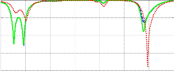
Fig.3 shows the simulation results of the E-shape and U-shape
based on the variations value of wh . When we use width of
the bridge 3.5 mm then bandwidth will increase but returnloss
will decrease. As resultant returnloss magnitude of the 3.5mm width is higher than the 2.5mm width.Therefore choosing the width of 3.5 mm will give the best response.
Changing substrate height (h)
-25
-50
2 2.5 3 3.5 4 4.5 5 5.5
-30
Frequency(GHz)
9
x 10
2 2.5 3 3.5 4 4.5 5 5.5
Fig.4: The variation of the of substrate height (h) on the return loss re-
Frequency(GHz)
9
x 10
sponse
TABLE III
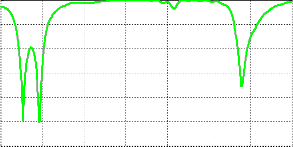
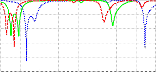
Fig.2: Return loss Simulation result of E-Shape & U-Shape Design
A connected microstrip E-shape and U-shape patch antenna has been designed with over all dimensions 33mm x 42 mm and height of 1.1 mm. Dual operation E-shape and U-shape Patch Antenna feed by transmission line is presented. In the following Fig.2 we analysis the return loss and then analysis the improved bandwidth using this connected set of E-shape
& U-shape.
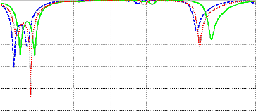
Substrate height(h) | Return loss | Magnitude(dB) |
1mm | 2.3 GHz & 4.693 GHz | -30.52 dB & -14.05 dB |
1.1mm | 2.464 GHz & 4.9GHz | -25.19 dB & -17.78 dB |
1.2mm | 2.41 GHz & 4.734 GHz | -43.64 dB & -20.9 dB |
Fig.4 shows the simulation results of the E-shape and U-shape based on the variations value of substrate height (h). It is clear from the figure that the magnitude of return loss will increase for the values of the substrate height 1, 1.1&1.2.
IJSER © 2012 http://www.ijser.org
International Journal of Scientific & Engineering Research Volume 4, Issue 1, January-2013 3
ISSN 2229-5518
But if Substrate height (h) is 1.1 mm then bandwidth will in- crease not only for 2.46GHz but also for 4.9 GHz.So, choosing the value of the substrate height of 1.1mm will give the best
response.
impedance bandwidth is increased for both 2.46 GHz and 4.9
GHz.So, choosing the dielectric constant of 6.15 will give the exact response.
TABLE V
3.3 The Effect of changing position of the Width (Wh )
Dielectric
Constant(Er)
Return loss Magnitude
0
-5
-10
Changing bridge position
4.4 2.664GHz& 5.728GHz -42.87 dB & -33.7 dB
6.15 2.464 GHz & 4.9GHz -25.19 dB & -17.78 dB
6.8 2.3 GHz & 4.668GHz -32.41 dB &-15.46 dB
-15
-20
-25
-30
-35
2
Fig.5: The variation of the position of the width (wh ) on the return loss
response
TABLE IV
Position of the width | Return Loss | Magnitude(dB) |
Y=16mm | 2.751 GHz & 4.9 GHz | -11.64 dB&-12.96 dB |
Y=17mm | 2.464 GHz & 4.9 GHz | -25.19 dB & -17.78 dB |
Y=18mm | 2.228 GHz & 4.973 GHz | -10.54 dB &-31.16 dB |
Fig.5 shows the simulation results of the E-shape and U-shape
based on the variations of the position of the width (wh ). It is
clear from the figure that the position of the width is y=17mm
then bandwidth will increase but returnloss will decrease.So, choosing the value of the position of the width of y=17mm
will give the best response.
stant (Er )
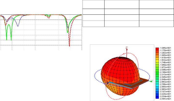
Fig.7: Gain at 2.46 GHz in 3D view
0
-10
-20
-30
-40
Changing dielectric constant (Er)
-50
2 2.5 3 3.5 4 4.5 5 5.5 6
Frequency(GHz)
9
x 10
Fig.6: The variation of the of substrate dielectric constant (Er ) on the re-
turn loss response
Fig.6 shows the simulation results of the E-shape and U-shape based on the variations value of substrate dielectric constant
(Er ). Here choosing the value of dielectric constant 6.15 then
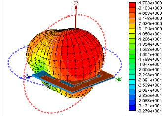
Fig.8: Gain at 4.9 GHz in 3D view
IJSER © 2012 http://www.ijser.org
International Journal of Scientific & Engineering Research Volume 4, Issue 1, January-2013 4
ISSN 2229-5518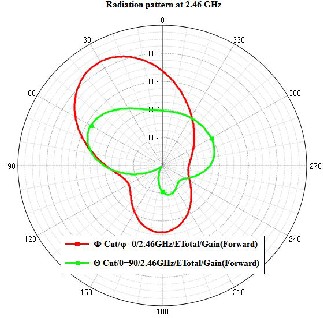
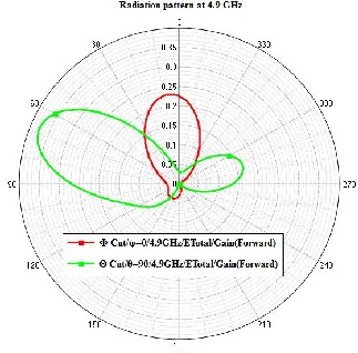
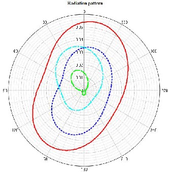
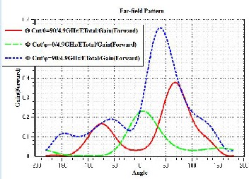
Fig.9: E-plane and H-plane at 2.46 GHz Fig.10: E-plane and H-plane at 4.9 GHz
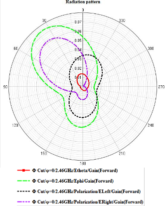
Fig.11: Elevation Pattern of E Right, E left, E theta, E Phi at 2.46 GHz for phi=0 (deg)
Fig.12: Elevation Pattern of E Right, E left, E theta, E Phi at 2.46 GHz for phi=90 (deg)
IJSER © 2012 http://www.ijser.org
International Journal of Scientific & Engineering Research Volume 4, Issue 1, January-2013 5
ISSN 2229-5518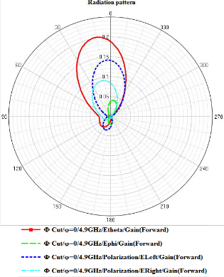
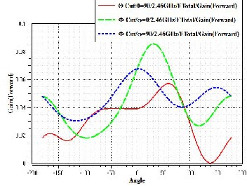
Fig.15: Simulated gain in 2D view of connected e-shape and u-shape at
2.46 GHz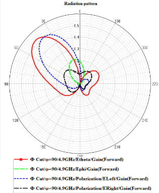
Fig.13: Elevation Pattern of E Right, E left, E theta, E Phi at 4.9GHz for phi=0 (deg)
Fig.16: Simulated gain in 2D view of connected E-shape and U-shape at
4.9 GHz
Fig.14: Elevation Pattern of E Right, E left, E theta, E Phi at 4.9 GHz for phi=90 (deg)
Connected E-shape and U-shape patch antenna is investigated and successfully simulated in this paper, the simulated return loss and the radiation pattern showed well performance for the dual band at 2.46 GHz and 4.9 GHz, the impedance band- widths for the dual band are 13.02 % and 3.28 %. The design shows suitable characteristic for dual-band operations. Using this Connected E-shape and U-shape patch antenna, band- width can be improved at two different frequencies at 2.46
GHz and 4.9 GHz for different wireless LAN application. It can be concluded from the above results that, designing a proper feed network and impedance matching are very im- portant parameters in microstrip patch antenna design. Also choosing a proper position for terminating the feed line affects the overall performance of the antenna. Different types of feed methods affect the performance of an antenna.
IJSER © 2012 http://www.ijser.org
International Journal of Scientific & Engineering Research Volume 4, Issue 1, January-2013 6
ISSN 2229-5518
In this paper, microstrip line feed is chosen. In the future study we would like to look at how other types of feed net- work will affect the performance of microstrip antennas as compared to the microstrip line feed. In this paper bandwidth is not too much at 4.9 GHz.The performance of bandwidth will be increased by using Proximity Coupled Feed.
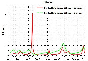
Fig.14: Radiation efficiency of connected E-shape and U-shape MSA
The authors would like to thank the teachers of the Depart- ment of Electronics and Telecommunication Engineering, RUET for providing me with best facilities and suggestions, All gratitude is due to “ALLAH” who guides me to bring forth to light this paper. All thanks due especially to my par- ents for their prayer and inspiration, which has helped me in becoming what I am today.
REFERENCES
[1] F. Yang, X.-X. Zhang, X. Ye, and Y. Rahmat-Samii, “Wide-band E-shaped patch antennas for wireless communications,” IEEE Trans.Antennas Propag., vol. 49, no. 7, pp. 1094–1100, Jul. 2001.
[2] B. L. Ooi and Q. Shen, “A novel E-shaped broadband microstrip patchantenna,” Microw. Opt. Technol. Lett., vol. 27, no. 5, pp.
348–352, Dec.5, 2000.
[3] Y. Ge, K. P. Esselle, and T. S. Bird, “Broadband E-shaped patch antennasfor 5–6 GHz wireless computer networks,” presented at the Proc.IEEE Antennas and Propagation Society.
[4] “E-shaped patch antennas for high-speed wireless net- works,”IEEE Trans. Antennas Propag., vol. 52, no. 12, pp. 3213–
3219, Dec.2004.
[5] M. Sanad, “Double C-patch antennas having different aperture shapes,”in Proc. IEEE Antennas and Propagation Dig., June
1995, pp.2116–2119.
[6] Deshmukh AA.“Compact broadband E-shaped microstrip an- tennas,”Electronics Letters. 2005;41(18):989-90.
[7] Murad NA, “Microstrip U-shaped dual-band antenna. Applied Electromagnetics,”, 2005 APACE 2005 Asia-Pacific Conference on. 2005:4 pp.
[8] Ooi BL, “A novel stacked E-shaped patch antenna,”. Antennas and Propagation Society International Symposium, 2001 IEEE.
2001;4:478,481 vol.4.
[9] Salonen P, “Dual-band E-shaped patch wearable textile anten- na,”. Antennas and Propagation Society International Symposi- um, 2005 IEEE. 2005;1A:466,469 Vol. 1A..
[10] Sang-Hyuk Wi, “Wideband microstrip patch antenna with U- shaped parasitic elements,”.Antennas and Propagation, IEEE Transactions on. 2007;55(4):1196-9.
[11] Singh D, “Small H-shaped antennas for MMIC applications,”.
Antennas and Propagation,IEEE Transactions on.
2000;48(7):1134-41.
[12] Tsz Ym Yum, “A novel H-shaped active integrated antenna,”.
Antennas and Propagation Society International Symposium,
2003 IEEE. 2003;2:708,711 vol.2.
[13] W.L. Stutzman and G.A. Thiele, Antenna Theory and Design,
2nd ed. New York: Wiley, 1998.
[14] C.A. Balanis, Antenna Theory, 2nd ed. New York: John Wiley & Sons, Inc., 1997.
[15] G. Kumar, K.P. Ray, "Broadband microstrip antenna", Artech
House Inc., 2003 .
[16] Jeong-Min JU, Gyey-Teak JEONG, Joong-Han YOON, Cheol- Soon KIM, Hyung-Sup KIM, and Kyung-Sup KWAK, “Design of Multiple U-Shaped Slot Microstrip Patch Antenna in 5 GHz Band WLAN,” IEICE Trans B: Communications E88-B: 821-825
International Journal of RF & Microwave CAE.
Authors profile :

Mohammad Mahabub Alam was born in Dinajpur, Bangladesh in 1990.He received the B.Sc. Degree in Electronics and Telecommunication Engineering from Rajshahi University of Engineering and Technology, Rajshahi-6204, Bangladesh. His research interests con- cerns the improvement of the bandwidth of the Mi- crostrip Patch antenna.Contact No:+8801715508498

Mohammad Suaibur Rahman was born in Rajshahi, Bangladesh in 1991. He received the B.Sc. Degree in Electronics and Telecommunication Engineering from Rajshahi University of Engineering and Technology, Rajshahi-6204, Bangladesh.His research interests con- cerns of the Microstrip Patch antenna design.Contact no:+8801817184339
IJSER © 2012 http://www.ijser.org