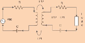
Fig. 1: An equivalent circuit model of inductive coupling cir- cuit.
ed or pick up current.
International Journal of Scientific & Engineering Research, Volume 4, Issue 12, December-2013 1580
ISSN 2229-5518
Wireless Power Transmission in Wireless Sensor
Network- A solution to the power constraint
Tanbir Ibne Anowar and Dr. Mohammad Ghanbarisabagh
Abstract— One of the major facts in W ireless Sensor Network (W SN) is its power constraint. In many critical cases, like sensors in hot oil pipe-lines may require urgent data from a selected node while the node is not waking up due to unhealthy battery life. Inductive coupling phenomena between two coils can easily solve it by wirelessly charging the previously placed coil inside that sensor. W ireless Power Transfer can be the solution on this concern. There are many alterable and unalterable factors that can govern the efficiency of W ireless Power Transfer. High Radio Frequency in lower coil radius with simple magnetic radiation mechanism can successfully transmit the power within a short distance at low cost. After pre-tuning resonant frequency, the optimum power transfer is possible through a constant efficiency in a short distance between nodes. Multi hop nodes can easily share the power from the source as well. A sensor can be placed anywhere when necessary, in that case the primary supply must be questionable and can be solved through the renewable energy.
Index Terms— Coupling coefficient, Impedance mismatch, Mutual inductances, Neumann’s formula, Resonance, W ireless Power
Transferand W ireless Sensor Network
—————————— ——————————
odern days are coming wrapped with a soft bound of simplicity and an awesomeness of fabulous technology.
ing the coil misalignment cases and successfully determine the effect over efficiency with an experimental verification. Into the
IJSER
Wireless Power Transfer (WPT) used in a charging unit
[1] brings the beauty in heathers as a little hope for the possibili-
ties of far field coupling mechanisms. Starting with a conven-
tional theory of Faraday’s Law of Magnetic induction along
with simple calculation of Neumann’s formula can lead the pro-
spective technology to low cost commercial goods through sim- ple circuit construction. In this paper, we focused on the simple, low cost construction of a charging system providing a concept of using renewable energy in a mostly power constrained appli- cation (e.g. Sensors). Using Magnetic coupling in a resonant circuit is widely used for its beneficiary significance of wireless- ly power transfer capabilities. From the last decade a huge work has been done in progress of WPT, Different methods has brought into the operations of WPT understanding the coupling between subsequent transmissions of wireless power. Besides the small equipment charging, WPT electrical vehicles as well as electric trains and robots are also capable of charging wirelessly [2-9].
According to the practical analysis, it is clear that the design is
suffered for some common reasons. In [10], describes the practi-
cal dependences of end to end efficiency of magnetically cou-
pled resonators. Achieving a good coupling coefficient with a large air gap depends on many important features. Impedance matching [11] is one of the great issues. In [12-16], these papers focus on the improved efficiency analysis depending on the coupling coefficient relating with air gap. In [17], they propose a power distribution analysis by matching the impedance be- tween the multi-coils. The paper [18], focuses on WPT consider-
————————————————
WPT, basic problem can be indicating as the separation of coils
where the electrical power is transferring along with the man-
ageable efficiency. According to the recent study, WiTricity was
proposed the theoretical implementation in 2007. The efficien-
cies are above approximately 50% within the distance of 2m
[19]. In [17], they have calculated the imaginary value of the reactive powers which is then balanced by other reactances pre- sent in the circuit. According to the calculation, for a single re- ceiver (Secondary coil) will experience a greater reactive power if the impedance mismatch factor is not wisely handled.
From recent works on WPT, We can introduce the method of wireless power transfer in three typical methods. (i) Coupled mode method (ii) Band-Pass Filter Method [20] and (iii) Equiva- lent circuit model. (Figure: 1) In [21], authors have calculated and proposed a band pass filter representation which is being analyzed considering the range between the pass bands, In [22], A method of introducing an intermediate coil between the transmitting and receiving coils is proposed where this concepts can be installed for a long transmission of WPT, also in [10], there method was a frequency tuning method for the optimum efficiency. (It can be proved theoretically by following to the solution of Helmholtz equation [23] relating angular frequency and magnetic field intensity). In the following papers[17, 24], authors have proposed a power division method by matching the impedance between coils. In this paper we have done the WPT with an experimental as well as simulation analysis using weakly coupled (k=0.011) inductive coil using the Neumann’s formula equation (1).
Major concern is given to the impedance mismatch factor as well as the coil alignment cases for getting maximum distances.
IJSER © 2013 http://www.ijser.org
International Journal of Scientific & Engineering Research, Volume 4, Issue 12, December-2013 1581
ISSN 2229-5518
Wireless power transmission has an enormous prospect on commercial and domestic uses. Power transmission on electric vehicle is studying widely and come to a successful through- put in this field. The basic problems on this type of transmis- sion are the separation distances between the coils, coupling phenomena, resonant frequency, quality factor, coils radii, coil alignments etc. Different types of method used to determine the efficiency and maximum separation distance.
Fig. 1: An equivalent circuit model of inductive coupling cir- cuit.
ed or pick up current.
Considering the applications, Wireless Sensor Network suffers the continuous power constraint. Different types of mode and distribution of clustering technique has brought with the con- cern of power management in a small sensor. Wireless Sensor Network (WSN) is a robust technology based on Wireless Networking without any infrastructure. The back bone of WSN belongs to the Wireless Ad hoc Network, following IEEE
802.15.4 Low rate WPAN Standard [25]. Unlike wired or wire- less infrastructure based network, which can be categorized by different topology, WSN structure is very much depends on application based. Basic advantage of WSN is its feasibility of working in rough environment. The Sensor nodes (which is on average known as ‘mote’) are typically consists of a micropro- cessor, digital radio, sensing unit and power supply [26]. In case of power assumption issue in WSN, many algorithms have been studied depend on application of establishing WSN. For an example, the idea of on demand schemes [27], scheduled rendezvous schemes [28, 29], asynchronous
wakeup schemes [30] or the idea of selective communications
IJSEor any type of wRake/sleep schemes [31-33] are performed suc-
Also a new method of distribution power in receiving coils is
discussed in [24]. Although the methods are very similar and the exact analysis of impedance inverters but the main prob- lem is neglecting cross coupling between the multi receivers, which is not ignorable, while a sufficient numbers of receiver will be used along with multi repeaters. Another major prob- lem is, the model is depends on coupling co-efficient and eve- ry time the tuning required for changing distance between transmitter and receiver coils, so that for a practical implemen- tation, auto tuning capabilities are required. In this paper, (Fig:![]()
![]()
2) renewable energy is being stored into a DC battery to sup- ply for the RF oscillator circuit after proper biasing (RF ampli- fier circuit is required and used).
cessfully for low power stability and cost. According to some of short discussion over Wireless Sensor Network it is clear that, an entire system is facing a short and limited capacity due to the power supply only. Fig: 3, is illustrating a new con- cept of distribution of power through WPT to the sensors where there is no other way of contact with the sensors after establishing. Using the multi receiver it is possible to transmit power through the intermediate nodes [34].
C
Charging battery through the WPT E
D B Coil
PV array
Load (Charging wirelessly)
Coil
Healthy battery life
A
Wireless Power
Transfer Circuit
Coil
Coil
Unhealthy battery life
Battery RF Oscillator RF Amplifier Wireless transmission via inductive coupling
Fig. 2: Basic block diagram of WPT.
An equivalent circuit model is analyzed and calculated the parameters for impedance matching as well as proper reso- nance. The application is primarily designed for the wireless sensor networks, as the sensors are low consumed power and at the same time energy constrained. But the similar analogy can be established into the other charging systems for the rat-
Fig. 3: Conceptual model of WPT in WSN.
For the maximum efficiency, usually the typical steps are
Impedance matching, Loss-less property of resonators,
IJSER © 2013 http://www.ijser.org
International Journal of Scientific & Engineering Research, Volume 4, Issue 12, December-2013 1582
ISSN 2229-5518
resonant frequency, Power generated at the primary coil, coupling co-efficient and Mutual inductance etc. Selection of perfect load impedance for the available transmitted power from the primary coil is also important for the practical analysis. Now, the Neumann’s Formula can be derived from the fundamental Biot-Savart’s Law,
Where, ‘Vind’ is the induced voltage at the secondary side. ‘a’ and ‘b’ is the coil radius of primary and secondary sides respectively, ω is the resonant angular frequency.
It can be stated from the faradays law of magnetic induction. Finally the efficiency becomes,![]()
L = µ0
N1 N 2
![]()
![]()
![]()
∫ ∫ dl1dl2
(1)
ω 2π 2 µ 2 N 2 N 2
η =
2
a 4 b 4 ( )
2 )3
12 4π
C1C 2 R
0 TX RX
![]()
16RTX RRX d + a
(6)
where, L12 is the Mutual inductance, N1 and N2 is the coil
turn number primary and secondary coils respectively, dl1
and dl2 are the differential length of coils primary and
secondary side respectively and ‘R’ is the separation between
two coils). Mutual inductance (L12) between coils can easily be achieved by the above formula again the relation between
Now, this formula only gives a complete concept of the factor depends on the efficiency. Clearly, η depends on the factors derived on coil’s parameters and resonance as well as impedances. For any fixed coils, we can write that,![]()
coupling coefficient and the mutual inductance can be found as;![]()
η = Kω 2
RTX
RRX
(d 2
+ a 2 )3
2 2 2
2 4 4
(7)
M 12
= κ12
LTX LRX
µ π
![]()
K = 0
N TX N RX a b
(2)
Where, k12 is the coupling coefficient, M12 is the mutual inductance; L1 and L2 are the inductance in Primary and Secondary side respectively. Coil designed is being done by,
Where, Multiplying factor, 16
Again considering the impedance matching factor, we can take, RTX = RRX = Z, so that, efficiency depends only on
resonant frequency, separation distance and the impedance
IJSER
2 8r
(3)
mismatch. In this paper I tried to focus on the simple![]()
L0 = N µ0 r ln − 1.75
a
mechanism to find out the simplest and easiest way of calculation the efficiency considering the environment of a
Where, ‘L0’ is the desired resonant coil inductance, ‘N’ is the turn number, ‘r’ is the coil radius and ‘a’ is the pitch of coil. Choice of taking equal amount of inductance both primary
sensor.![]()
η =
Kω 2 K
=
and secondary sides will make an easy way to determine the impedance matching in both sides. That is, we will now focus on the resistive and capacitive impedances. Unless tuning the
Z (d 2 + a 2 )3
R 2 + X
L X C
+ jR( X L
− X C
![]()
)(d 2 + a 2 )3
(8)
capacitance, it is required to tune the resonant frequency so that the coil on both sides will resonate at same frequency and
So that, for any fixed distance,
the efficiency will be high.
Fig. 4: An equivalent circuit model of a Wireless Power
Transfer circuit.
η =
R 2 + X
L X C
![]()
K1
+ jR( X L
− X C )
K = K
(9)
Neumann’s formula derived from the conventional Biot-![]()
1 2
Where, Multiplying factor, d
+ a 2 )3
Savart’s law is a key to measure the mutual inductance.
Efficiency for using two coils can be derived as,
Now, at resonant, XL = XC so that efficiency will become,![]()
![]()
η = PRX (100%) =
P 4R
2
ind
R I 2
(100%)
![]()
η = K1
R + X L X C
(10)
TX TX
RX TX
(4)
Where, XL
= ωL0
and XC
= 1/ωC0 . And the resonant
Here, η is the efficiency of power transmission, ‘PRX ’ and ‘PTX ’ is the power at receiving and transmitting side. Here, induced voltage on the secondary side can be designed as,
ω 0 =
frequency,![]()
1
L 0 C 0
![]()
2 2 2
2 2 2 2
2 2 4 4
From the relation, it is understood that for any change![]()
![]()
Vind =
jωπµ0 NTX N RX I TX a b
2R 3![]()
= ω π µ0 NTX N RX I TX a b
4R 6
(5)
of mismatching resonant frequency with a lower amount will take effect of serious degradation at the efficiency though for high ‘Q’. If the deviation of the actual frequency versus
IJSER © 2013 http://www.ijser.org
International Journal of Scientific & Engineering Research, Volume 4, Issue 12, December-2013 1583
ISSN 2229-5518
resonant frequency becomes wider than its cutoff frequency than there will be no power transmission through the entire system.
Impedance matching is evident in WPT, the
following equations:
K 2
κ = 01
01 R ω L
circumstances of impedance mismatching will degrade the
maximum efficiency can be discussed further with a simple
0 0 1
2
(14)![]()
![]()
η = S 2 ×100%
![]()
κ = K 23
23 R ω L
network, where,
L 0 2
(15)
S = 2 jω0 LM Z L
K12
![]()
21 ω 2 L2
+ (Z
+ Z ) 2
![]()
κ12 =
0 M L 2
(11)
ω0 L1 L2
(16)
Where, S21 is the transmission efficiency from primary side to
the secondary sides, ZL is the load impedance, Z2 is the matched impedance in the secondary sides, LM is the mutual
Where, From above equation κ01 and κ23 are the coupling coefficient between L01 to primary coil and L23 to secondary
κ12
inductance and ω0 is the resonant angular frequency.
coil respectively.
is the coupling coefficient between the
So that for the maximum case it can be shown that,
primary and secondary coils. R0 and RL are the input and
output impedance (Which is considered same ‘R’). C1 and C2
2 2 2 2 0
ω0 LM + Z L − Z 2 =
Thus the need of impedance matching could realize from the equation and also, LM can be chosen easily from this equation. From the mutual inductance, coupling coefficient could be studied easily, In this paper, the mutual inductance is found using Neumann’s formula and found 0.16μH and the coupling
are the coupling capacitor for the coils to be resonance at the resonant frequency, ω0 .
Now, Coupling coefficient κ12 is found, κ12 = 0.011, for the
impedance inverter design we consider, κ12 = κ01 = κ23 = 0.011 and found the characteristics impedance, K01 and K23 are
equal and same, 25.61Ω (cause, R0 and RL are considered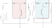
IJSER
coefficient is found 0.011 (Here, we took an arbitrary data to
focus on applying the mentioned method for a distance of
Inverter, K01
Impedance
same).
k12
r2
Inverter, K23
In this paper, the proposed concept of mitigating the power
constraint problem in Wireless Sensor Network come up with
C01
C01 C23 C23
R C1
R
two coils surrounding each of the node. Two coils can conduct
+ L01
Vs
-
2cm).
L23
1
2
r1 C2
at the same time and transfer power continuously. Most pow-
er constrained node can send data to the cluster head by send-
ing additional flag message and thus the power transmission
will begin. Actual power will be cultivated from the renewable sources like solar power. After getting voltage from PV (Pho- to-voltaic) solar array, precisely +12 V is maintained through a
Thus, coupling co-efficient κ12 can be found from the
conventional formula on equation (2) where mutual
inductance is known by the Neumann’s formula.
Fig. 5: Impedance matching equivalent circuit diagram.
From figure-5, an impedance matching inverting is designed which is virtually considered for the impedance matching calculation of load and to show the coupling between primary and secondary coils. Measured current (I1 and I2 ) can be expressed as,
voltage regulator. We used a current controlled amplifier to biasing the incoming voltage. When biasing is done, an RF oscillator circuit should be made with 13.56 MHz of resonant frequency. We used a ‘Hartley oscillator’ circuit to produce RF frequency of 13.56 MHz (Amplification of the output of RF oscillator circuit must be done with an RF amplifier circuit) which is not necessary to produce an extra burden for the sen- sor nodes (Typical RF used on the Sensors is 13.56 MHz). Im- pedance matching network is a pre-calculated for setting ca- pacitance and resistance for the constructed coils (Primary and secondary). According to the objectives, sensors must be de- signed along with the two coils on both sides![]()
I = 2(Z L + Z 2 )
1 ω 2 L2
+ (Z
+ Z ) 2
0 M L 2
(12)![]()
I = 2 jωLM
2 ω 2 L2
+ (Z
+ Z ) 2
0 M L 2
(13)
Considering the configuration as a ‘Butterworth response’, low pass filter equation can be achieved which gives rise to the
IJSER © 2013 http://www.ijser.org
International Journal of Scientific & Engineering Research, Volume 4, Issue 12, December-2013 1584
ISSN 2229-5518
Renewable Energy from Solar panel,
+12V
DC biasing
with voltage regulator
and BJT
RF
Oscillator
circuit,
13.56 MHz
Load
RF
Amplifier
circuit, amplify up to 10 VP-P
Impedance
Impedance Matching Network,
(Z0)
Receiving
Transmitting coil,
L1=14 uH
(N=10, a=0.035m)
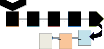
Figure 9, is a practical approach taken after the calculation had been done. Results showing that the magnetic flux density generated by the short circuit operation of primary coil is 0.52 mT. This is standardized by the ISO and IEC 61000 standards for domestic and commercial uses. The efficiency versus dis- tance curve gives an easy analytical result, which shows the
Output efficiency,
32.65%
Fig. 6: Step by step methodology
Matching Network, (ZL)
coil,
L2 = 14 uH
parameter distance will vary the efficiency. In this paper, the
physical construction of the prototype of wireless power trans-
fer based on WSN is studied for the separation distance of the
coils is 2cm. According to the following figure 7 and 8, we can
We use the center tapped coil as a primary coil considering N=10 with a low coil radius (3.5 cm). Considering the low ‘Q’ (5.5) the simulation results found that primary coil is deliver- ing constant current of 4 mA peak to peak and the oscillation is stable. The stability of the oscillation in the following figure (8) indicates the impedance matching on the primary and sec- ondary sides.
see the condition for the efficiency to be decreased along with the increasing separation distance. Resonant frequency 13.56
MHz adjusted carefully after the construction of RF frequency, from the RF oscillator, a sensitive adjustment is necessary by changing the capacitance to achieve into the resonant frequen- cy. It can be shown that how poorly the efficiency deviates due to detuning.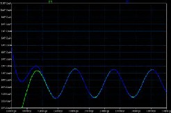
3
2
IJSE1 R
0
-1
Fig. 7: Primary coil current I (L1) and I (L2) together after 1.5
μs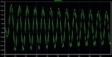
Fig. 8: Voltage found at resonant capacitance (damping condi- tion).
-2
-3
-3 -2 -1 0 1 2 3
Separation of two nodes in WSN, coupled by Inductive coupling
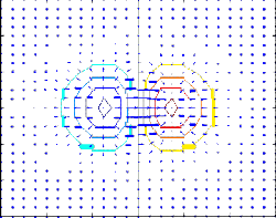
Fig. 10: Magnetic flux line sharing scenario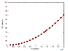
Fig. 11: Efficiency versus optimum frequency curve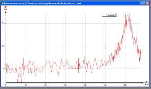
Fig. 9: Practical measurements of Magnetic Flux density
IJSER © 2013 http://www.ijser.org
International Journal of Scientific & Engineering Research, Volume 4, Issue 12, December-2013 1585
ISSN 2229-5518
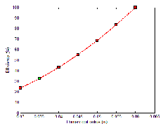
Fig. 12: Efficiency versus coils radius curve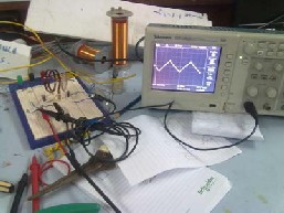
Fig. 15: An output of 20mV peak to peak is found at the re- ceiver side for 2cm of separation distances.
In this paper, wireless power transfer into the WSN can be considered under some certain points of requirements. The feasibility of the transmission in worst case is considered for the entire experimental setup. But, some common facts must be maintained for optimum case. High quality factor ‘Q’ must take under the rough circumstances to get the narrow fre- quency width and high output for the critical frequency. In case of a small difference of resonant frequency (Δω), Efficien-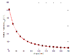
cy drops rustically though the ‘Q’ factor is being chosen high.
Impedance matching is calculated considering the ‘impedance inverter’ in both sides of the coupled inductors using ‘Band
Fig. 13: Mutual inductance versus separation distance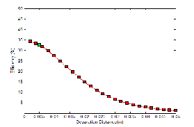
Fig. 14: Efficiency versus coil separation distance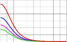
60
50
40
30
20
10
0
pass method’. Selecting load for the paramount power transfer is one of the key features of WPT. Choice of selecting re- sistance confined the power at load. Coil misalignment in lat- eral and angular misalignment could happen for arbitrary set up of WSN nodes for the multi hop. The coupling coefficient k12 is in between 0~1 but for the low power assumption nodes require a strong coupling between them. Higher frequency will lead a good system performance but sensitive calibration.
A new model of circuit construction is illustrated and proved the transmission of wireless power through a small distance with only two RF amplifiers and conventional oscillator cir- cuit. Our proposed method consists of simple algorithm and calculations with a cheap but efficient circuitry for commercial aspects. Simulation results demonstrate the similarity found by previously done practical works. A prototype was built to prove the new simplest method. But, tuning of resonant fre- quency through the variable capacitor was difficult and so- phisticated. In future, a varistor could be introduced to replace the variable capacitor. Four coils transmission technique could be introduced for the further study for WSN.
Our pleasant gratitude to the Ministry of Science and Infor-
0 0.01 0.02 0.03 0.04 0.05 0.06 0.07 0.08 0.09 0.1
Separation Distance (m)
Fig. 15: Efficiency versus coil separation distances in different internal coil resistances, from top to bottom R=40Ω, 50Ω, 60Ω and 70Ω
mation Technology for their financial support during the time
of research at University of Malaya.
IJSER © 2013 http://www.ijser.org
International Journal of Scientific & Engineering Research, Volume 4, Issue 12, December-2013 1586
ISSN 2229-5518
[1] J. Y. a. M. M. Jovanovic, "A contactless electrical energy transmission system for portable-telephone battery chargers," IEEE Trans. Ind.Electron, vol. 50, p. 7, June, 2003.
[2] J. L. V. J. Sallan, A. Llombart and J. F. Sanz, "Optimal design of ICPT systems applied to electric vehicle battery charge," IEEE Trans. Ind.Electron., vol. 56, p.
5, June, 2009.
[3] L. M. C. Geng, M. Denai, and Y. Hori, "Direct yaw-moment control of an in- wheel-motored electric vehicle based on body slip angle fuzzy observer," IEEE Trans. Ind. Electron, vol. 56, p. 9, May, 9 2009.
[4] S. O. D. Yin, and Y. Hori, "A novel traction control for EV based on maximum transmissible torque estimation," IEEE Trans. Ind. Electron., vol. 56, p. 14, Junem 2009 2009.
[5] A. A. a. T. Ohno, "A power reception and conversion system for remotely- powered vehicles," Proc. ICAP, vol. 1, p. 4, April 1989.
[6] O. H. S. C.-S. Wang, and G. A. Covic, "Design considerations for a contactless electric vehicle battery charger," IEEE Trans. Ind. Electron, vol. 52, p. 7, Octo- ber 2005.
[7] T. N. Y. Kamiya, T. Sato, J. Kusaka, Y. Daisho, S. Takahashi, and K. Narusawa, "Development and performance evaluation of advanced electric micro bus equipped with non-contact inductive rapid-charging system," Proc. 23rd Int. EVS, Elect./Hybrid-Elect. Session, p. 14, December 2007.
[8] S. N. a. M. Hiroshi, "Wireless charging system by microwave power transmis-
sion for electric motor vehicles," IEICE Trans. Electron, vol. J87-C, p. 11, 2004.
"Wireless power transfer via strongly coupled magnetic resonance," Science, vol. 317, pp. 1819-1825, July 6, 2007 2007.
[20] B. T. C. Koh Kim Ean, Takehiro Imura and Yoichi Hori, "Novel Band-Pass Filter Model for Multi-Receiver Wireless Power Transfer via Magnetic Reso- nance Coupling and Power Division," presented at the IEEE 13th Annual Wireless and Microwave Technology Conference (WAMICON), 2012.
[21] I. A. a. T. Komori, "A simple and versatile design method of resonator- coupled wireless power transfer system," presented at the 2010 International Conference of Communications Circuits and Systems (ICCCAS), , 2010.
[22] H. C. S. J. W. Kim, K. H. Kim and Y. J. Park, "Efficiency analysis of magnetic resonance wireless power transfer with intermediate resonant coil," Antennas and Wireless Propagation Letters, IEEE, vol. 10, pp. 389-392, 2011 2011.
[23] A. D. Polyanin, Handbook of Linear Partial Differential Equations for Engi-
neers and Scientists. CRC Press LLC, 2000 N.W. Corporate Blvd., Boca Raton, Florida 33431: Chapman & Hall/CRC, 2002.
[24] T. C. B. K. E. Koh, T. Imura and Y. Hori, "Multi-receiver and Repeater Wire- less Power Transfer via Magnetic Resonance Coupling –Impedance Matching and Power Division Utilizing Impedance Inverter," presented at the 15th In- ternational Conference on Electrical Machines and Systems (ICEMS), 2012.
[25] I. R. N.Salman, A.H.Kemp, "Overview of the IEEE 802.15.4 standards family for Low Rate Wireless Personal Area Networks," in 7th international Sympo- sium on Wireless Communication Systems (ISWCS), 2010, pp. 701-705.
[26] M. C. Giuseppe Anastasi, Mario Di Francesco, Andrea Passarella "Energy conservation in wireless sensor networks: A survey " 2008.
IJSER
[9] J. K. N. Shinohara, T. Mitani, T. Hashimoto, N. Kishi, S. Fujita, T. Mitamura, H. Tonomura, and S. Nishikawa, "Assessment study of electric vehicle charg- ing system with microwave power transmission II," Tee. Rep. IEICE, vol. SPS2006, p. 3, 2007.
[10] D. A. M. Alanson P.Sample, and Joshua R. Smith, "Analysis, Experimental Results, and Range adaption of Magnetically Coupled Resonators for Wire- less Power Transfer," IEEE Trans. Ind. Electron, vol. 58, pp. 544-554, February,
2011 2011.
[11] M. K. T.C Beh, T.Imura and Y. Hori, "Basic Study of Improving Efficiency of Wireless Power Transfer via Magnetic Resonance Coupling Based on Im- pedence Matching," IEEE Int. Symp. Ind. Electron. (ISIE 10), pp. 2011-2016,
2010.
[12] F. K. S. Rajagopal, "Multiple receiver support for magnetic resonance based wireless charging," presented at the 2011 IEEE Int. Conf. on Communications Workshops (ICC), 2011.
[13] T. Imura, "Optimization using transmitting circuit of multiple receiving an- tennas for wireless power transfer via magnetic resonance coupling," in 2011
IEEE 33rd Int. Telecommunications Energy Conf. (INTELEC), 2011, pp. 1-4.
[14] J. F. H. B. L Cannon, D. D. Stancil, and S. C. Goldstein, "Magnetic resonant coupling as a potential means for wireless power transfer to multiple small re- ceivers," IEEE Trans. Power Electron, vol. 24, pp. 1819-1825, July, 2009 2009.
[15] R. M. a. M. S. A. Kurs, "Simultaneous mid-range power transfer to multiple devices," Applied Phsics Letter, vol. 96, p. 3, January, 2010 2010.
[16] J. W. K. e. al, "Analysis of wireless energy transfer to multiple devices using
CMT," in 2010 Asia-Pacific Microwave Conf. Proc. (APMC), 2010, pp. 2149-
2152.
[17] B. T. C. Koh Kim Ean, Takehiro Imura and Yoichi Hori "Impedance Match- ing and Power Division Algorithm Considering Cross Coupling for Wireless Power Transfer via Magnetic Resonance," in Telecommunication Energy Conference (INTELEC), 2012, pp. 1-5.
[18] K. F. a. B. W. Flynn, "Wireless power transfer in loosely coupled links: Coil misalignment model," IEEE Transactions on Magnetics, vol. 47, pp. 416-430,
26 January, 2011 2011.
[19] A. Kurs, A. Karalis, R. Moffatt, J. D. Joannopoulos, P. Fisher, and M. Soljacic,
[27] A. G. M. Roc´ıo Arroyo-Valles, Jes´us Cid-Sueiro, "Optimal Selective Forward-
ing for Energy Saving in Wireless Sensor Networks," IEEE Transactions on
Wireless Communications, vol. 10, pp. 164-175, 2011.
[28] Y. R. Faizulkhakov, "Time Synchronization Methods for WirelessSensor Networks: A Survey," Programming and Computer Software, Plenum Press, vol. 33, 2007.
[29] B. Y. F. Sivrikaya, "Time synchronization in sensor networks: a survey," IEEE Network, vol. 18, pp. 45-50, 2004.
[30] C. H. Y. Tseng, T. Hsieh, "Power saving protocols for IEEE 802.11 adhoc net- works," in IEEE Infocom 2002, New York, USA, 2002.
[31] W. Y. Y. Li, J. Heidemann, "Energy and latency control, in low duty cycle MAC protocols," in Proceedings on IEEE Wireless Communication and Net- working Conference, New Orleans, USA, 2005.
[32] N. S. G. Lu, B. Krishnamachari, A. Goel, "Delay efficient sleep scheduling in wireless sensor networks," in Proceedings on IEEE Infocom 2005, 2005.
[33] [33] B. K. G. Lu, C.S. Raghavendra, "An adaptive energyefficient and low- latency Mac for data gathering in wireless sensor networks," in Proceedings on18th International Parallel and Distributed Processing Symposium, pp. 26-
30.
[34] C. K. L. a. S. Y. R. H. Wenxing Zhong, "General Analysis on the Use of Tesla’s Resonators in Domino Forms for Wireless Power Transfer," IEEE Transac- tions on Industrial Electronics, vol. 60, pp. 261-270, 2013
IJSER © 2013 http://www.ijser.org