International Journal of Scientific & Engineering Research, Volume 5, Issue 2, February-2014 20
ISSN 2229-5518
Wireless Power Transmission from Solar Power
Satellite
Shyma.S, Sindhuja.E
Abstract— A great concern has been voiced in recent years over the extensive use of energy, the limited supply of resources, and the pollution of the environment from the use of present energy conversion systems. Electrical power accounts for much of the energy consumed. Much of this power is wasted during transmission from power plant generators to the consumer. The resistance of the wire used in the electrical grid distribution system causes a loss of 26-30% of the energy generated. This loss implies that our present system of electrical distribution is only 70-74% efficient. Nikola Tesla is best known for his remarkable statements regarding the wireless transmission of electrical power. His first efforts towards this end started in
1891 and were intended to simply "disturb the electrical equilibrium in the nearby portions of the earth... to bring into operation in any way some instrument." In other words the object of his experiments was simply to produce effects locally and detect them at a distance.
Index Terms—Geostationary Earth Orbit, Grid distribution, Power Transmission Efficiency, Rectenna, Space Solar Power Satellite, Wireless
Transmission
—————————— ——————————
T is known that electromagnetic energy is associated with the propagation of electromagnetic waves. Theoretically, we can use
all electromagnetic waves for a wireless power transmission (WPT). The difference between the WPT and communication systems is only efficiency. Maxwell’s Equations indicate that the electromag- netic field and its power diffuse to all directions. Though we trans- mit energy in a communication system, the transmitted energy is diffused to all directions. Though the received power is enough for a transmission of information, the efficiency from the transmitter to receiver is quiet low. Therefore, we do not call it the WPT system.
Typical WPT is a point-to-point power transmission. For the WPT, we had better concentrate power to receiver. It was proved that the power transmission efficiency can approach close to 100%. We can more concentrate the transmitted microwave power to the receiver aperture areas with taper method of the transmitting an- tenna power distribution. Famous power tapers of the transmitting antenna are Gaussian taper, Taylor distribution, and Chepachet distribution. Such taper of the transmitting antenna is commonly used for suppression of side lobes. It corresponds to increase in the power transmission efficiency. Concerning the power transmission efficiency of the WPT, there are some good optical approaches in Russia.
Future suitable and largest application of the WPT via microwave is a Space Solar Power Satellite (SPS). The SPS is a gigantic satellite designed as an electric power plant orbiting the Geostationary Earth Orbit (GEO). It consists of mainly three segments; solar ener- gy collector to convert the solar energy into DC (direct current) electricity, DC-to-microwave converter, and large antenna array to beam down the microwave power to the ground. The first solar collector can be either photovoltaic cells or solar thermal turbine. The second DC-to-microwave converter of the SPS can be either microwave tube system and/or semiconductor system. It may be their combination. The third segment is a gigantic antenna array. Table 1.1 shows some typical parameters of the transmitting
antenna of the SPS. An amplitude taper on the transmitting antenna is adopted in order to increase the beam collection efficiency and to decrease side lobe level in almost all SPS design. A typical ampli- tude taper is called 10 dB Gaussian in which the power density in the center of the transmitting antenna is ten times larger than that on the edge of the transmitting antenna.
The SPS is expected to be operational around 2030. Before realiza- tion of the SPS, we can consider other applications of WPT. In re- cent years, mobile devices advanced significantly and require de- creasing power consumption. It means that we can use the diffused weak microwave power as power source of the mobile devices with low power consumption such as RF-ID. The RF-ID is radio IC-tug with wireless power transmission and wireless information. This is a new WPT application like broadcasting.
In 1864, James C. Maxwell predicted the existence of radio waves by means of mathematical model. In 1884, John H. Poynting realized that the Poynting vector would play an important role in quantifying the electromagnetic energy. In 1888, bolstered by Max- well's theory, Heinrich Hertz succeeded in showing experimental evidence of radio waves by his spark-gap radio transmitter. The prediction and evidence of the radio wave in the end of 19th centu- ry was start of the wireless power transmission.
During the same period of Marchese G. Marconi and Re- ginald Fessenden who are pioneers of communication via radio waves, Nicola Tesla suggested an idea of the wireless power trans- mission and carried out the first WPT experiment in 1899[1][2]. of one to a few horse-powers. One of its chief uses will be the illumi- nation of isolated homes”. He said “This energy will be collected all over the globe preferably in small amounts, ranging from a frac- tion He actually built a gigantic coil which was connected to a high mast of 200-ft with a 3 ft-diameter ball at its top.
IJSER © 2014 http://www.ijser.org
International Journal of Scientific & Engineering Research, Volume 5, Issue 2, February-2014 21
ISSN 2229-5518
Fig.1 MPT Demonstration with helicopter by W.C. .Brown
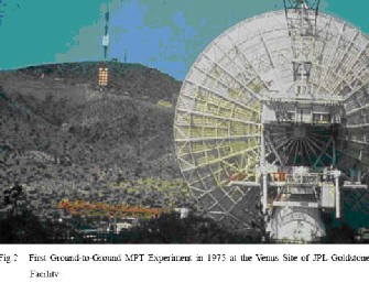
In parallel, he and his team succeeded in the largest MPT demon- stration in 1975 at the Venus Site of JPL Goldstone Facility (fig 2). Distance between a transmitting parabolic antennas, whose diame- ter was 26m, and a rectenna array, whose size was 3.4 m x 7.2 m, was 1 mile.
He fed 300 Kw power to the Tesla coil resonated at 150 kHz. The RF potential at the top sphere reached 100 MV.Unfortunately, he failed because the transmitted power was diffused to all directions with
150 kHz radio waves whose wave length was 21 km.
To concentrate the transmitted power and to increase transmission efficiency, we have to use higher frequency than that used by Tesla.
In 1930s, much progress in generating high-power microwaves, namely 1-10 GHz radio waves, was achieved by invention of the magnetron and the klystron. After World War II, high power and high efficiency microwave tubes were advanced by development of radar technology. We can concentrate a power to receiver with mi- crowaves. We call the wireless power transmission with micro- waves as microwave power transmission (MPT). Based on the de- velopment of the microwave tubes during the World War II, W. C. Brown started the First MPT research and development in 1960. First of all, he developed a retina, rectifying antenna which he named, for receiving and rectifying microwaves. The efficiency of the first rectenna developed in 1963 was 50 % at output 4WDC and
40% at output 7WDC, respectively [3].
With the rectenna, he succeeded in MPT experiments to wired heli- copter in 1964 and to free-flied helicopter in1968 (Fig. 1). In 1970s; he tried to increase DC-RF-transmission-RF-DC total efficiency with
2.45 GHz microwave. In 1970, overall DC-DC total efficiency was only 26.5 % at 39WDC in Marshall Space Flight Center.
After 1990s, many MPT laboratory and field experiments were car- ried out in the world. We often use 2.45 GHz or 5.8 GHz of the ISM band (ISM=Industry, Science, and Medical) for the MPT system. A Canadian group demonstrated fuel-free airplane flight experiment with MPT in 1987 which was called SHARP (Stationary High Alti- tude Relay Platform) with 2.45 GHz.
Fig.3 Stationary High Altitude Relay Platform
In USA, there were many MPT research and development projects after W. C. Brown: for instance, retro directive microwave transmit- ters, rectenna, new devices and microwave circuit technologies.
IJSER © 2014 http://www.ijser.org
International Journal of Scientific & Engineering Research, Volume 5, Issue 2, February-2014 22
ISSN 2229-5518
In Japan, there were many field MPT experiments such as fuel-free airplane flight experiment with MPT phased array with 2.411 GHz in 1992, ground-to-ground MPT experiment with Power Company and universities in 1994-95.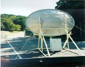
Fig. 4 Ground-to-Ground MPT Experiment in Japan in 1994-95
All antennas can be applied for both the MPT system and commu- nication systems, for example, Yagi-Uda antenna, horn antenna, parabolic antenna, micro strip antenna, phased array antenna or any other type of antenna. To fixed target of the MPT system, we usually select a large parabolic antenna, for example, in MPT demonstration in 1975 at the Venus Site of JPL Goldstone Facility and in ground-to-ground MPT experiment in 1994-95 in Japan. In t he fuel-free airship light experiment with MPT in 1995 in Japan, they changed a direction of the parabolic antenna to chase the mov- ing airship .However, we have to use a phased array antenna for the MPT from/to moving transmitter/receiver which include the SPS because we have to control a microwave beam direction accu- rately and speedily. The phased array is a directive antenna which generates a beam form whose shape and direction by the relative phases and amplitudes of the waves at the individual antenna ele- ments.It is possible to steer the direction of the microwave beam. The antenna elements might be dipoles [1], slot antennas, or any other type of antenna, even parabolic antennas [2, 3]. In some MPT experiments in Japan, the phased array antenna was adopted to steer a direction of the microwave beam (Fig.5). All SPS is designed with the phased array antenna.
The technology employed for generation of microwave radiation is an important subject for the MPT system. We need higher efficient generator/amplifier for the MPT system than that for the wireless communication system. For highly efficient beam collection on rectenna array, we need highly stabilized and accurate phase and
amplitude of microwaves for phased array system for the MPT. There are two types of microwave generators/amplifiers. One is a microwave tube and the other is semiconductor amplifier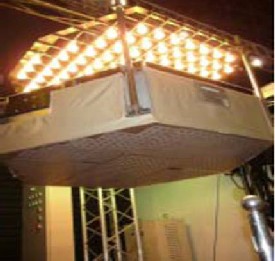
Fig.5 Phased Array used in Japanese Field MPT experiment
Magnetron is a crossed field tube in which electrons emitted from the cathode take cyclical path to the anode. The magnetron is self- oscillatory device in which the anode contains a resonant RF struc- ture. The magnetron has long history from invention by A. W. Hull in 1921.
The practical and efficient magnetron tube attracted worldwide interest only after K. Okabe proposed divided anode-type magnetron in 1928. Magnetron technologies received a boost dur- ing the World War II, especially with the Japanese Army. The mag- netrons were also useful for microwave ovens. As a result, the magnetron of 500 – 1,000 W is widely in use for microwave ovens in
2.45 GHz, and is a relatively inexpensive oscillator (below $5).
There is a net global capacity of 45.5GW/year for all magnetrons used in microwave ovens whose production is 50– 55 millions. It was W. C. Brown who invented a voltage controlled oscillator with a cooker-type magnetron in PLL.
After 1980s, semiconductor devices became dominant in microwave world instead of the microwave tubes. This was driven by advances in mobile phone networks. The semiconductor device is expected to expand microwave applications, for example, phased array and active integrated antenna (AIA), because of its manageability and mass productivity. After 1990s, some MPT experiments were
carried out in Japan with phased array of semiconductor amplifi-
ers.Typical semiconductor devices for microwave circuits are FET (Field Effect Transistor), HBT (Hetero junction Bipolar Transistor), and HEMT (High Electron Mobility Transistor). Present materials for the semiconductor devices are Si for lower frequency below a
IJSER © 2014 http://www.ijser.org
International Journal of Scientific & Engineering Research, Volume 5, Issue 2, February-2014 23
ISSN 2229-5518
few GHz and GaAs for higher frequency. It is easy to control phase and amplitude through the microwave circuits with semiconductor devices, for example, amplifiers, phase shifters, modulators, and so on.Currently, new materials are under development to enable semi- conductor devices yield increased output power and efficiency.
Largest MPT application is a SPS in which over GW microwave will be transmitted from space to ground at distance of 36,000km. In the SPS, we will use microwave transmitters in space. For space use, the microwave transmitter will be required lightness to reduce launch cost and higher efficiency to reduce heat problem. A weight of the microwave tube is lighter than that of the semiconductor am- plifier when we compare the weight by power-weight ratio (kg/kW). The microwave tube can generate/amplify higher power microwave than that by the semiconductor amplifier. Kyoto Uni- versity’s groups have developed a light weight phase controlled magnetron called COMET, Compact Microwave Energy Transmit- ter with a power-weight ratio below 25g/W (fig.3.2.). The COMET includes DC/Converters, a control circuit of the phase controlled magnetron with 5.8 GHz, a heat radiation circuit, a wave guide, and an antenna [4]. The power-weight ratio of the COMET is lightest weight in all microwave generators and amplifiers.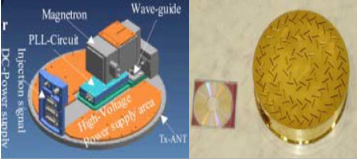
Fig. 6 Compact Microwave Energy Transmitter with the PCM (COMET)
TWTA for satellite use has lighter power weight ratio: 220Wat
2.45GHz at 2.65 kg (the TWTA weighs 1.5kg, the power supply weighs 1.15kg). 130W at 5.8 GHz at 2.15 kg (the TWTA weighs
0.8kg, the power supply weighs 1.35kg). Hence, they can deliv-
er12g/W and 16.5g/W, respectively. They do not include a heat radi- ation circuit, a wave guide, and an antenna.
A microwave power transmission is suitable for a power transmis- sion from/to moving transmitters/targets. Therefore, accurate target detection and high efficient beam forming are important. Retro di- rective system is always used for SPS. A corner reflector is most basic retro directive system. The corner reflectors consist of per- pendicular metal sheets, which meet at an apex. Incoming signals are reflected back in the direction of arrival through multiple reflec- tions off the wall of the reflector. Van Atta array is also a basic tech-
nique of the retro directive system. This array is made up of pairs of antennas spaced equidistant from the center of the array, and con- nected with equal length transmission lines. The signal received by an antenna is re-radiated by its pair, thus the order of re-radiating elements are inverted with respect to the center of the array, achiev- ing the proper phasing for retro directivity. Usual retro directive system have phase conjugate circuits in each receiving/transmitting antenna, which play same role as pairs of antennas spaced equidis- tant from the center of the array in Van Atta array. The signal is called a pilot signal. We do not need any phase shifters for beam forming. The retro-directive system is usually used for satellite communication, wireless LAN, military, and so on.
One of the characteristics of the MPT is to use more intense micro- wave than that in wireless communication systems. Therefore, we have to consider MPT safety for humans.
(a) two-sided corner reflector, (b) Van Atta Array, (c) retrodirective array with phase conjugate circuits.
In general, effect of atmosphere on microwaves is quite small. There are absorption and scatter by air, rain, and irregularity of air refrac- tion ratio. In 2.45 GHz and 5.8 GHz, the absorption by water vapor and oxygen dominate the effect in the air. Especially, it is enough to consider only absorption by the oxygen in the microwave fre- quency. It is approximately 0.007dB/km. In the SPS case, the amount of total absorption through the air from space is approxi- mately 0.035 dB.
When microwaves from SPS propagate through ionospheric plas- mas, some interaction between microwaves and the ionospheric plasmas occurs. It is well known that refraction, Faraday rotation, scintillation, and absorption occur between weak microwave used for satellite communication and the plasmas. However, influence on the MPT system is negligible. It is nonlinear interaction between intense microwave and the space plasmas that we have to investi- gate before the commercial SPS. We theoretically predict that the
IJSER © 2014 http://www.ijser.org
International Journal of Scientific & Engineering Research, Volume 5, Issue 2, February-2014 24
ISSN 2229-5518
following may occur: heating of the plasmas, plasma hall effect, thermal self-focusing effect of the microwave beam, and three-wave interactions and excitation of electrostatic waves in MHz bands. These interactions will not occur in existent satellite communication systems because microwave power is very weak.
Point-to-point MPT system needs a large receiving area with a rectenna array because one rectenna element receives and creates only a few W. Especially for the SPS, we need a huge rectenna site and a power network connected to the existing power networks on the ground. On contrary, there are some MPT applications with one small rectenna element such as RF-ID.
The word “rectenna” is composed of “rectifying circuit” and “antenna”. The rectenna can receive and rectify a microwave power to DC. The rectenna is passive element with a rectifying diode, op- erated without any power source. The circuit, especially diode, mainly determines the RF-DC conversion efficiency. Silicon Schott- ky barrier diodes were usually used for earlier rectenna. New de- vices like SiC and GaN are expected to increase the efficiency. The rectenna with FET or HEMT appear ed recently. The single shunt full-wave rectifier is always used for the rectenna. It consists of a diode inserted in the circuit in parallel, a λ/4 distributed line, and a capacitor inserted in parallel. In an ideal situation, 100% of the re- ceived microwave power should be converted into DC power.
Fig. 7 Efficiency of Rectenna Element
The beam collection efficiency depends on the transmitter and re- ceiver aperture areas, the wavelength, and the separation distance between the two antennas.
Electrical energy can be economically transmitted without wires to any terrestrial distance. The economic transmission of power without wires is of crucial importance to man. It will enable him to dispense with innumerable causes of sinful waste. This technology opened up the possibility of constructing power stations on the moon. These power stations will be capable of transmitting power
to earth using microwave energy. Such microwave energy would then be converted into electricity using a vast array of rectenna receivers on the earth.
Nevertheless with all the challenges that face wide-scale
deployment of this new technology wireless power transmission for solar power satellite is still considered as a next-generation power transmission system.
The rectenna will be used as an array for high power MPT because one rectenna element rectifies a few W only. For usual phased array antenna, mutual coupling and phase distribution are problems to solve. For the rectenna array, problem is different from that of the array antenna because the rectenna array is connected not in mi- crowave phase but in DC phase.
When we connect two rectenna in series or in parallel, they will not
operate at their optimum power output and their combined power
output will be less than that if operated independently. This is theo- retical prediction.
We classify the MPT efficiency roughly into three stages; DC-RF conversion efficiency which includes losses caused by beam form- ing, beam collection efficiency which means ratio of all radiated power to collected power on a receiving antenna, and RF-DC con- version efficiency.
The RF-DC conversion efficiency of the rectenna or the CWC is over
80 % of experimental results as shown. Decline of the efficiency is caused by array connection loss, change of optimum operation point of the rectenna array caused by change of connected load, trouble of the rectenna, and any losses on the systems, for example, DC/AC conversion, cables, etc. [6] However, it is easier to realize higher efficiency than that on the other two stages.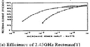
[1] N.Tesla, “The Transmission of Electric Energy without Wires”, Electrical
World, March 5, 1904.
[2] W.C.Brown, “Beamed Microwave Power Transmission and its Application to
Space”, IEEE Trans. Microwave Theory Tech., vol. 40, no. 6, 1992, pp.1239-1250.
[3] N. Kaya, S. Ida, Y. Fujino, and M. Fujita, “Transmitting Antenna system for
Airship demonstration of Space Energy and Transportation” IEEE Vol.1, No.4,
1996, pp.237-245.
[4] E. Fujiwara, Y. Takahashi, N. Tanaka, K. Saga, “Compact Microwave Energy
IJSER © 2014 http://www.ijser.org
International Journal of Scientific & Engineering Research, Volume 5, Issue 2, February-2014 25
ISSN 2229-5518
Transmitter (COMET)”, Proc. of Japan-US Joint Workshop on SSPS (JUSPS),
2003, pp.183-185.
[5] T. Hatsuda, K. Ueno, M. Inoue, “Solar Power Satellite Interference Assess- ment”, IEEE, Vol. 3, No. 4, Dec. 2002, pp.65-70.
[6] J.O.McSpadden, L. Fun, and K. Chang, “A High Conversion Efficiency 5.8
GHz Rectenna”, IEEE MTT-S Digest, 1997, pp.547-550.
[7] M.F Iskander, “Electromagnetic Fields and Waves”, Prentice Hall, 1992.
[8] Ed. Chang, K., “Handbook of Microwave and Optical Components Volume
1”, A Wiley-Interscience Publication, 1989, p.511.
[9] G.Goubau and F. Schwering, “On the Guided Propagation of Electromagnet- ic Wave Beams”, IRE Trans. Antennas and Propagation, AP-9, 1961, pp. 248-256. [10 ] R.B. Vaganov,“Maximum Power Transmission between Two Apertures with the Help of a Wave Beam”, Journal of Communications Technology and Electronics, vol.42, no.4, 1997,pp.430-435.
[11] V.N.Garmash, ,B.Z. Katsenelenbaum , S.S.Shaposhnikov, S.S, V. N. Tioulpa- kov, and R. B.Vaganov, “Some Possible Methods of the Diffraction Expansion Decrease”, Proc.of SPS’97,1997. pp.87-923.
[12] H.Matsumoto,, “Research on Solar Power Station and Microwave Power Transmission in Japan : Review and Perspectives”, IEEE Microwave Magazine, December 2002, pp.36-45.
[13] N.Shinohara and H. Matsumoto, “Dependence of dc Output of a Rectenna Array on the Method of Interconnection of Its Array Element”, Electrical Engi- neering in Japan, Vol.125, No.1,1998, pp.9-17.
[14] T.A.Takano , and N. Kamo, “Simplification Techniques of the Constitution of Microwave Transmission Antennas of SPS (in Japanese)”, Tech. Rep. of IEICE, SPS2003-09(SPS2004-02), 2004, pp.51-58.
[15] Xu, H. C. Sanabria, A. Chini, S. Keller, U. K. Mishra, and R. A. York, “A C- Band High-Dynamic Range GaN HEMT Low-Noise Amplifier”, IEEE Micro- wave and Wireless Componets Lett., Vol.14, No.6, 2004, pp.262-264.
IJSER © 2014 http://www.ijser.org