International Journal of Scientific & Engineering Research, Volume 5, Issue 7, July-2014 1178
ISSN 2229-5518
Waste process steam heat recovery system
Rana Darshak D
Abstract - Waste heat is heat generated in a process by way of fuel combustion, chemical reaction or process steam, which is then “dumped” into the environment and not reused for useful and economic purposes. The essential fact is not the amount of heat, but rather its “value”. The mechanism to recover the unused heat depends on the temperature of the waste heat and the economics involved. Large quantities of process steam are exhausted into the environment by pharmaceutical and chemical industries. If some of the waste heat could be recovered then a considerable amount of primary fuel could be saved. The energy lost in waste steam cannot be fully recovered. However, much of the heat could be recovered and adopting the following measures as outlined in this project report can minimize losses. In any heat recovery situation it is essential to know the amount of heat recoverable and also how it can be used. The most commonly used waste heat recovery methods are preheating combustion air, steam generation and water heating, and load preheating. Low pressure steam may also be used to preheat the feed water. This principle is used in Indirect Contact Heat Exchanger and finds wide use in a steam generating station. W hen a vapor contains the waste heat, it usually condenses, giving up its latent heat to the liquid being heated, i.e. feed water. Present work is based on the recovery of the waste heat of process steam, utilizing that energy, i.e. Increasing the temperature of the feed water by using shell & tube heat exchanger. The topic presented aim is enhancing the efficiency of the process This is reflected by reduction in the utility consumption & costs, and process cost.
Index Terms – Design of a condenser, heat recovery system, waste process steam
1. INTRODUCTION
1.1 Brief on the company visited
The industry that we visited as a part of Project was Zydus Cadila Healthcare. Zydus Cadila is an innovative global pharmaceutical company that discovers, develops, manufactures and markets a broad range of healthcare products..
The industrial training took place at Zydus Cadila Healthcare Ltd., Ankleshwar. Zydus Cadila's plant complex at Ankleshwar in Bharuch District of Gujarat has been producing drug material since 1972. There are around 10 plants in the complex, which is ISO 9002 and ISO
14001 certified.
Total plant capacity at Ankleshwar is around 180 million
tones. Zydus Cadila's API/Bulk Drug Plant in Ankleshwar
is the oldest manufacturing facility of the Company.
Basically, all the solvents required to produce the drugs are
being manufactured at Ankleshwar. These solvents are
then sent to Ahmedabad for the manufacturing of the
required drug.
1.2 Description of the plant in which the problem was observed
The problem was in the “Solvent recovery plant
(S.R.P.)”.The detailed description of the plant is as follows.
SOLVENT RECOVERY PLANT (S.R.P.)
As the name suggests, the main aim of solvent recovery
plant is to recover the useful solvents from the various
chemical mix. WORKING:-
The mixture of various solvent which is obtained as a discharge from all the plants is collected in a tank. From this tank it is pumped inside the reactor. Surrounding the
reactor is a reactor jacket in which the steam at high temperature is introduced. This steam in the reactor jacket
is used to heat the mixture of solvent inside the reactor. Thus vapour of the solvent mixture is obtained.

From the reactor the vapour of solvent mixture is passed to the column. Here the constituents of the mixture of the solvent are separated as per their boiling point. The solvent with lower boiling point forms the vapour earlier than the other and passes to the primary condenser. Once that solvent gets condensed, it passes to the secondary condenser. Later the other solvent with higher boiling point vaporizes and passes to the primary and secondary condenser once the vapour of the former solvent is condensed fully. From the secondary condenser the condensate passes into the reflux drum where part of the condensate is drawn out as product and part of it is passed back to the column. Rota meter is provided to measure the rate at which the product is formed as well as the rate at which the condensate is sent back to the column. In this way the mixture of various solvent is separated.
Fig.1.1: Process of S.R.P
1.3 Explanation of the problem in detail
The steam used in S.R.P comes from UTILITY BLOCK-1
Boiler having capacity of 2 tons. Steam is supplied at SRP at
3.5 Kg/cm² (3.567 bar) having flow rate on average of 4500
IJSER © 2014 http://www.ijser.org
International Journal of Scientific & Engineering Research, Volume 5, Issue 7, July-2014 1179
ISSN 2229-5518
kg/hr in dry saturated conditions having enthalpy of 2732 kJ/kg. Now this steam is used in reactor jacket where heat exchange take place and steam losses its heat to solvent which gets the heated and vaporized. On the basis of input steam quality we can say that on average 65% heat of steam is utilized in the reactor jacket which is given to solvent so the exhaust steam coming out of reactor jacket still consists of 35% of heat having enthalpy of 2315kJ/kg. Now this 35% heat of exhaust steam in the form of condensate is send to reboiler drum. Here a vent is provided above the drum. The exhaust steam from the reactor jacket settles down and it is send to feed water tank by using pump which can be used again for further generation of steam. But in the reboiler drum the dry steam that cannot be condensed at atmospheric temperature on its own rises at upper level and comes out of the drum through vent and this steam (approx.) 25% of inlet steam
flow rate having enthalpy of 2040 kJ/kg is send in sewage
line which is completely wasted, and from this sewage line
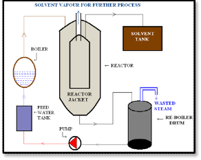
the waste feed goes to effluent treatment plant (E.T.P).
Fig: 1.2: Schematic diagram of the problem
2. BRIEF HISTORY OF WORK
The main purpose of our work was to minimize
Table 2.1: Parameters of the steam obtained from the boiler
the wastage of the steam by recovering the waste heat of the process steam. The steam initially wasted can thus be used into same or any other form
2.1 Technical parameters
Temperature 138.8ºC

Table 2.2: Parameters of the exhaust steam coming out of the reactor jacket
2.2 Work Plan
The wasted steam has enthalpy 2040 kJ/kg and pressure
0.45 bar. Now this steam doesn’t contain enough energy to
transfer the heat so it cannot be used directly. So it is
convenient to condense this steam with the help of a
CONDENSER, hence the produced hot water can be used
in the boiler for the generation of steam.
The exhaust coming out of the reactor jacket in which 25% of heat of the steam is wasted as mentioned ago and the remaining part of the exhaust which condenses by itself at atmospheric temperature and pressure both are sent to the feed water tank for its use in the boiler.
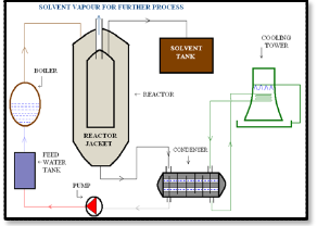
Thus we can improve the process by condensing the exhaust of the reactor jacket entirely.
Fig 2.1: Schematic diagram of work plan
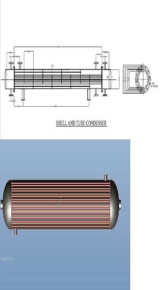
2.3 Identification of a suitable condenser
The most suitable condenser as a part of our problem and its solution would be the SURFACE CONDENSER (down flow type) due to the following advantages.
• Cooling water and steam are not mixed, hence we can get pure condensate which can be directly pumped into the boiler
• A
ny kind of feed water can be used. Since the
makeup water requirements are low (only 5 to
10%), the cost of water softening plant is reduced.
• It can develop high vacuum, therefore, these are suitable for large capacity power plant.
IJSER © 2014 http://www.ijser.org
International Journal of Scientific & Engineering Research, Volume 5, Issue 7, July-2014 1180
ISSN 2229-5518
• It requires less power to run the air extraction pump.
• It requires less power for water pumping and this system is more efficient
In a recuperator, heat exchange takes place between the flue gases and the air through metallic or ceramic walls. Ducts or tubes carry the air for combustion to be preheated; the other side contains the waste heat stream
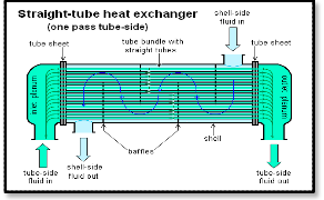
Fig 2.2: Shell and tube type condenser
3. LITERATURE SURVEY
3.1 An overview of the waste heat recovery
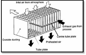
3.1: Waste Heat Recovery using Recuperator
• Convective recuperator
Fig
Waste heat is heat generated in a process by way of fuel combustion or chemical reaction, which is then “dumped” into the environment and not reused for useful and economic purposes. The essential fact is not the amount of heat, but rather its “value”. The mechanism to recover the unused heat depends on the temperature of the waste heat gases and the economics involved. If some of the waste heat could be recovered then a considerable amount of primary fuel could be saved. The energy lost in waste gases cannot be fully recovered. However, much of the heat could be recovered and adopting the following measures one can minimize losses
3.2 Heat Losses – Quality & Quantity
Depending upon the type of process, waste heat can be rejected at virtually any temperature from that of chilled cooling water to high temperature waste gases from an industrial furnace or kiln. Usually higher the temperature, higher the quality and more cost effective is the heat recovery. In any study of waste heat recovery, it is absolutely necessary that there should be some use for the recovered heat. With high temperature heat recovery, a cascade system of waste heat recovery may be practiced to ensure that the maximum amount of heat is recovered at the highest potential. An example of this technique of waste heat recovery would be where the high temperature stage was used for air pre-heating and the low temperature stage used for process feed water heating or steam raising. In any heat recovery situation it is essential to know the amount of heat recoverable and also how it can be used
3.3 Types of waste heat recovery equipment Various commercial equipment that can be used to recover waste heat and for other applications are mentioned below.
• Recuperators
IJSER © 2014
A second common configuration for recuperators
is called the tube type or convective recuperator.
As seen in the figure below, the hot gases are
carried through a number of parallel small
diameter tubes, while the incoming air to be heated enters a shell surrounding the tubes and passes over the hot tubes one or more times in the direction normal to their axes.
Fig 3.2: Convective Recuperator
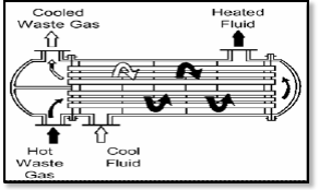
• Shell and Tube Heat Exchanger
When the medium containing waste heat is a liquid or a vapor which heats another liquid, then the shell and tube heat exchanger must be used since both paths must be sealed to contain the pressures of their respective fluids. The shell contains the tube bundle, and usually internal baffles, to direct the fluid in the shell over the tubes in multiple passes. When a vapor contains the waste heat, it usually condenses, giving up its latent heat to the liquid being heated. In this application, the vapor is almost invariably contained within the shell. If the reverse is attempted, the condensation of vapors within small diameter parallel tubes causes flow instabilities.
http://www.ijser.org
International Journal of Scientific & Engineering Research, Volume 5, Issue 7, July-2014 1181
ISSN 2229-5518
• Regenerators
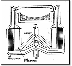
Regenerators are suitable for large capacities and have been widely used in glass and steel melting furnaces. Important relations exist between the sizes of the regenerator, time between reversals, thickness of brick, conductivity of brick and heat storage ratio of the brick. Long periods would mean higher thermal storage and hence higher cost. Also long periods of reversal result in lower average temperature of preheat and consequently reduction in the fuel economy.
Fig 3.3: Regenerator
• Direct Contact Heat Exchanger
Low pressure steam may also be used to preheat the feed water or some other fluid where miscibility is acceptable. This principle is used in Direct Contact Heat Exchanger and finds wide use in a steam generating station. They essentially consist of a number of trays mounted one over the other or packed beds. Steam is supplied below the packing while the cold water is sprayed at the top. The steam is completely condensed in the incoming water thereby heating it.
3.4 Benefits of waste heat recovery
Benefits of ‘waste heat recovery’ can be broadly classified in two categories:
1) Direct Benefits:
Recovery of waste heat has a direct effect on the
efficiency of the process. This is reflected by
reduction in the utility consumption & costs, and process cost.
2) Indirect Benefits:
a) Reduction in pollution:
A number of toxic combustible wastes such as carbon monoxide gas, sour gas, carbon black off gases, oil sludge, Acrylonitrile and other plastic chemicals etc, releasing to atmosphere if/when
burnt in the incinerators serves dual purpose i.e. recovers heat and reduces the environmental pollution levels.
b) Reduction in equipment sizes:
Waste heat recovery reduces the fuel
consumption, which leads to reduction in
the flue gas produced. This results in
reduction in equipment sizes of all flue
gas handling equipments such as fans, stacks, ducts, burners, etc.
c) Reduction in auxiliary energy consumption:
Reduction in equipment sizes gives additional benefits in the form of
reduction in auxiliary energy consumption like electricity for fans, pumps etc.
3.5 Economic Evaluation of waste heat recovery system
It is necessary to evaluate the selected waste heat recovery system on the basis of financial analysis such as investment, depreciation, payback period, rate of return etc. In addition the advice of experienced consultants and suppliers must be obtained for rational decision.
Many industrial processes require large quantities of thermal energy, much of which is eventually exhausted to the environment, either to the atmosphere or water. Recovering this waste heat represents the largest opportunity for reducing industrial energy consumption in the U.S. Carolyn J. Roos,[A] Ph.D. WSU Extension Energy Program, presented the paper which reviewed an overview of industrial waste heat recovery technologies for moderate temperatures. The old rule of thumb that industrial heat recovery is cost effective only for temperatures of at least
1000ºF is not true today with increasing energy prices, technological development by equipment manufacturers and decreasing equipment costs.
Thermal design of shell-and-tube heat exchangers is done by sophisticated computer software. However, a good understanding of the underlying principles of exchanger
design is needed to use this software effectively. Rajiv Mukherjee[B], Engineers India Ltd.has worked on effectively design of shell-and-Tube heat exchangers. The article presented by him explains the basics of exchanger thermal design, covering such topics as: STHE components, classification of STHEs according to construction and according to service, data needed for thermal design, tube side design, shell side design, including tube layout, baffling, and shell side pressure drop; and mean temperature difference.
John E. Edwards[C] focused on. The optimum thermal design of a shell and tube heat exchanger involves the consideration of many interacting design parameters like process fluid assignments to shell side or tube side, selection of stream temperature specifications, setting shell side and tube side pressure drop design limits, setting shell side and tube side velocity limits and selection of heat
IJSER © 2014 http://www.ijser.org
International Journal of Scientific & Engineering Research, Volume 5, Issue 7, July-2014 1182
ISSN 2229-5518
transfer models and fouling coefficients for shell side and tube side.
3.6 Introduction to condenser
The purpose of the condenser in a vapor compression cycle is to accept the hot, high-pressure gas from the compressor and cool it to remove first the superheat and then the latent heat, so that the refrigerant will condense back to a liquid. In addition, the liquid is usually slightly sub cooled. In nearly all cases, the cooling medium will be air or water.
3.7 Function of condenser
1.Conservation of pure feed water:
Very large quantities of steam pass though a
turbine. It would, of course, be not only very
wasteful but almost impracticable to allow this
vast amount of steam to be exhausted to atmosphere. By using a condenser the exhaust steam is converted back to hot water which is removed from the condenser for continuous use in the power station heat cycle. This water is known as condensate. It being free from impurities and non-condensable gases does not produce corrosive action and also it being hot (@ 40-50 C), saves a considerable amount of fuel. Thus the overall efficiency of the plant is increased.
2.De aeration of make-up water:
Due to leakage, blowing down, steam soot
blowing, etc., some of the feed water in the boiler/turbine system is lost, and must be made- up. Make-up water is usually supplied from Reserve Feed Water (RFW) tanks, where the air in contact with the water surface introduces oxygen into the RFW. Dissolved oxygen in feed water must be kept to the lowest practicable minimum, since oxygen causes corrosion of tubes.
The most convenient method of removing oxygen form the make-up water is to admit this water to the condenser, where due to the very low pressure and corresponding low boiling point, the water flashes off to steam, and dissolved oxygen separates off to be removed with other air and gases by the air-ejectors.
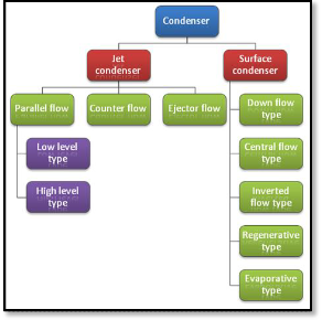
3.8 Classification of condenser
Fig 3.4: Types of condenser
• JET CONDENSERS
In jet condensers the exhaust steam and the cooling water come in direct contact and as a result the steam is condensed.
1) Parallel-Flow type of jet condenser:
The exhaust steam and cooling water find their
entry at the top of the condenser and then flow downwards and condensate and water are finally collected at the bottom.
a) Low level jet condenser:-
As shown, L, M and N are the perforated
trays which break up water into jets. The
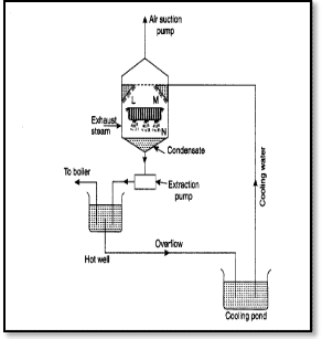
steam comes in contact with water and gets condensed. The condensate is sent to the hot well by extraction pump and the air is removed by an air suction pump.
Fig 3.5: Low level jet condenser
IJSER © 2014 http://www.ijser.org
International Journal of Scientific & Engineering Research, Volume 5, Issue 7, July-2014 1183
ISSN 2229-5518
b) High level jet condenser:
It is also called barometric condenser. In this
type the shell is placed at a height about 10.363 meters above hot well and thus the necessity of providing an extraction pump can be avoided.
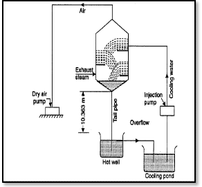
Fig 3.6: High level jet condenser
2) Counter-Flow type of jet condenser:
The steam and cooling water enter the condenser from opposite directions. Generally, the exhaust steam travels in upward direction and meets the cooling water which flows downwards.
3) Ejector Flow type of jet condenser:
Here the exhaust steam and cooling water mix in
hollow truncated cones. Exhaust steam along with
associated air is finally lead to diverging cone. And
the condensate consisting of condensed steam,
cooling water and air is discharged into the hot well.
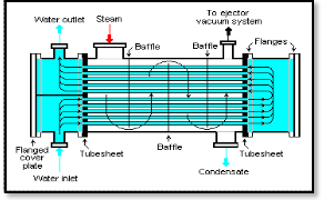
• SURFACE CONDENSERS
The exhaust steam and water do not come into direct contact. The steam passes over the outer surface of tubes through which cooling water flows.
1) Down Flow Type: The cooling water flows in the
tubes from the lower half section and after
traveling through the upper half section comes out
through the outlet. The exhaust steam entering
shell from the top flows down over the tubes and gets condensed.
Fig 3.7: Down flow type surface condenser
2) Central Flow Type: In this type of condenser, the suction pipe of the air extraction pump is located in the centre of the tubes which results in radial flow of the steam. The better contact between the outer surface of the tubes and steam is ensured.
3) Inverted flow type: In this type of condenser the steam after entering at the bottom rises up and then again flows down to the bottom of the condenser as condensate, by following a path near the outer surface of the condenser.
4) Regenerative type: In this type of the condenser the
condensate is passed through the entering exhaust steam, thus raising the temperature of the condensate, for use as feed water for the boiler.
5) Evaporative type: This type of condenser is used when limited quantity of water plants are
available. The exhaust steam enters at the top through gilled pipes. The water pump sprays water on the pipes and descending water condenses the steam. The water which is not evaporated falls into cooling pond from which it can be drawn and used over again.
3.9 Components of shell and tube type heat exchanger (STHE)
It is essential for the designer to have a good working knowledge of the mechanical features of STHEs and how they influence thermal design.
The principal components of an STHE are:
• Shell
• Shell cover
• Tubes
• Channel
• Channel cover
• Tube sheet
• Baffles and nozzles
Other components include tie-rods and spacers, pass partition plates, impingement plate, longitudinal baffle, sealing strips, supports, and foundation. The Standards of the Tubular Exchanger Manufacturers Association (TEMA) (1) describe these various components in detail.
A STHE is divided into three parts:
• Front head
• Shell
• Rear head.
IJSER © 2014 http://www.ijser.org
International Journal of Scientific & Engineering Research, Volume 5, Issue 7, July-2014 1184
ISSN 2229-5518
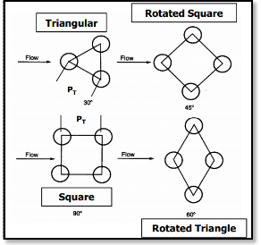
Figure 3.8 illustrates the TEMA nomenclature for the various construction possibilities. Exchangers are described by the letter codes for the three sections — for example; a BFL exchanger has a bonnet cover, a two-pass shell with a longitudinal baffle, and a fixed-tube sheet rear head.
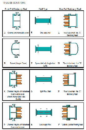
Fig3.8: TEMA designations for shell and tube condensers
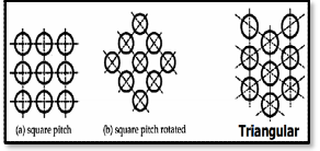
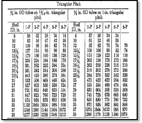
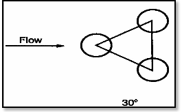
3.10 Tube layout patterns
There are four tube layout patterns, as shown in Fig 3.9 triangular (30°), rotated triangular (60°), square (90°), and rotated square (45°). A triangular (or rotated
Triangular) pattern will accommodate more tubes than a
square (or rotated square) pattern. Furthermore, a
triangular pattern produces high turbulence and therefore a
high heat-transfer coefficient. However, at the typical tube pitch of 1.25 times the tube O.D., it does not permit mechanical cleaning of tubes, since access lanes are not available.
Consequently, a triangular layout is limited to clean shell
side services. For services that require mechanical cleaning on the shell side, square patterns must be used. Chemical cleaning does not require access lanes, so a triangular layout may be used for dirty shell side services provided chemical cleaning is suitable and effective.
Fig 3.9: Tube layout patterns (a)
A rotated triangular pattern seldom offers any advantages
over a triangular pattern, and its use is consequently not very popular. For dirty shell side services, a square layout is typically employed. However, since this is an in-line pattern, it produces lower turbulence. Thus, when the shell side Reynolds number is low (< 2,000), it is usually advantageous to employ a rotated square pattern because this produces much higher turbulence, which results in a higher efficiency of conversion of pressure drop to heat transfer.
As noted earlier, fixed-tube sheet construction is usually employed for clean services on the shell side, U-tube
construction for clean services on the tube side, and floating-head construction for dirty services on both the shell side and tube side. (For clean services on both shell side and tube side, either fixed-tube sheet or U-tube construction may be used, although U-tube is preferable since it permits differential expansion between the shell and the tubes.) Hence, a triangular tube pattern may be used for fixed-tube sheet exchangers and a square (or rotated square) pattern for floating-head exchangers. For U- tube exchangers, a triangular pattern may be used provided the shell side stream is clean and a square (or rotated square) pattern if it is dirty.
Fig 3.10: Tube layout patterns (b)
3.11 Tube pitch
Tube pitch is defined as the shortest distance between two adjacent tubes.
IJSER © 2014 http://www.ijser.org
International Journal of Scientific & Engineering Research, Volume 5, Issue 7, July-2014 1185
ISSN 2229-5518
For a triangular pattern, TEMA specifies a minimum tube pitch of 1.25 times the tube O.D. Thus, a 25- mm tube pitch is usually employed for 20-mm O.D. tubes. For square patterns, TEMA additionally recommends a minimum cleaning lane of 4 in. (or 6 mm) between adjacent tubes. Thus, the minimum tube pitch for square patterns is either
1.25 times the tube O.D. or the tube O.D. plus 6 mm,
whichever is larger.
For example, 20-mm tubes should be laid on a 26-mm (20 mm + 6 mm) square pitch, but 25-mm tubes should be laid on a 31.25-mm (25 mm ´ 1.25) square pitch. Designers prefer to employ the minimum recommended tube pitch, because it leads to the smallest shell diameter for a given number of tubes. However, in exceptional circumstances, the tube pitch may be increased to a higher value, for example, to reduce shell side pressure drop. This is particularly true in the case of a cross-flow shell.
3.12 Baffling
• Type of baffles.
Baffles are used to support tubes, enable a desirable velocity to be maintained for the shell side fluid, and prevent failure of tubes due to flow- induced vibration.
There are two types of baffles:
• Plate
• Rod.
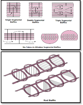
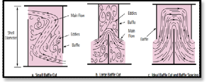
Plate baffles may be single-segmental, double- segmental, or triple-segmental, as shown in fig 3.11
• Baffle spacing.
Baffle spacing is the centerline-to-centerline
distance between adjacent baffles. It is the most vital parameter in STHE design. The TEMA standards specify the minimum baffle spacing as one-fifth of the shell inside diameter or 2 in.,
IJSER © 2014 http://www.ijser.org
whichever is greater. Closer spacing will result in poor bundle penetration by the shell side fluid and difficulty in mechanically cleaning the outsides of the tubes. Furthermore, a low baffle spacing results in a poor stream distribution as will be explained later. The maximum baffle spacing is the shell inside diameter. Higher baffle spacing will lead to predominantly longitudinal flow, which is less efficient than cross-flow, and large unsupported tube spans, which will make the exchanger prone to tube failure due to flow-induced vibration.
For turbulent flow on the shell side (Re > 1,000), the heat-transfer coefficient varies to the 0.6–0.7 power of velocity; however, pressure drop varies to the 1.7–2.0 power. For laminar flow (Re < 100), the exponents are 0.33 for the heat-transfer coefficient and 1.0 for pressure drop. Thus, as baffle spacing is reduced, pressure drop increases at a much faster rate than does the heat-transfer coefficient. This means that there will be an optimum ratio of baffle spacing to shell inside diameter that will result in the highest efficiency of conversion of pressure drop to heat transfer. This optimum ratio is normally between 0.3 and 0.6
• Baffle cut.
As shown in Figure 8, baffle cut is the height of the segment that is cut in each baffle to permit the shell side fluid to flow across the baffle. This is expressed as a percentage of the shell inside diameter. Although this, too, is an important parameter for STHE design, its effect is less profound than that of baffle spacing. Baffle cut can vary between 15% and 45% of the shell inside diameter. Both very small and very large baffle cuts are detrimental to efficient heat transfer on the shell side due to large deviation from an ideal situation, as illustrated in Fig 3.12.
Fig 3.12 Effect of small and large baffle cuts
It is strongly recommended that only baffle cuts
between 20% and 35% be employed. Reducing
baffle cut below 20% to increase the shell side heat-
transfer coefficient or increasing the baffle cut
beyond 35% to decrease the shell side pressure
drop usually lead to poor designs. Other aspects of tube bundle geometry should be changed instead to achieve those goals. For example, double segmental baffles or a divided-flow shell, or even a cross-flow shell, may be used to reduce the shell
International Journal of Scientific & Engineering Research, Volume 5, Issue 7, July-2014 1186
ISSN 2229-5518
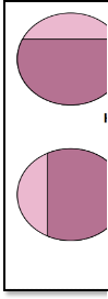
side pressure drop. For single-phase fluids on the shell side, a horizontal baffle cut (Fig 3.12) is recommended, because this minimizes accumulation of deposits at the bottom of the shell and also prevents stratification
Mass flow rate, mh | 4500 kg/hr |
Entering Temperature, T1 | 78 oC |
Specific Heat Capacity, Cph | 2.014 kJ/kg-k |
Viscosity Of Exhaust steam, µh | 0.00042 kg/m-s |
Thermal Conductivity, kh | 0.5623 w/m-k |
Density, ρh | 0.5542 kg/m3 |
Fig 3.13: Baffle cut orientation
4. IMPLEMENTATION OF WORK
The implementation of the work plan results in the detailed design of the Shell and Tube type condenser.
4.1 Design Statement
Exhaust steam at 0.44 bar and at a rate of 4500 kg/hr is to be condensed to get condensate at 75ºC by using cooling water from 30oC to 40oC.Thus we design a shell and tube heat exchanger to perform the above duty.
This section includes the following design:
• Thermal Design.
• Hydraulic Design.
GENERAL STEPS FOR DESIGNING SHELL AND TUBE CONDENSER
• STEP 1.
Obtain the necessary thermo physical properties of hot and cold fluid streams at their mean temperature
• STEP 2.
Perform the energy balance and calculate heat exchanger duty.
• STEP 3.
Calculate the logarithmic mean temperature difference (LMTD).
• STEP 4.
Assume a reasonable value of the overall coefficient on outside tube area, designated as Udo and calculate the heat transfer area..
• STEP 5
Select the tube diameter, its wall thickness (In Terms Of BWG) and the tube length. Calculate the number of tubes required to provide the area calculated above. Check the reliability for single pass arrangement. Also estimate the tube side heat transfer coefficient.
• STEP 6.
Select the tube arrangement. Also select the shell diameter that can accommodate the required number of tubes.
• STEP 7.
Select the type, size (e.g. percentage cut) number and spacing of baffles.
• STEP 8.
Estimate the shell side heat transfer coefficient.
• STEP 9.
If the shell side heat transfer coefficient comes to be very small through calculations then assume another suitable heat transfer coefficient for the shell side.
• STEP 10.
Select the fouling factors Rfi and Rfo applicable to the system.
• STEP11.
Calculate the overall coefficient Ucal.
• STEP 12.
Calculate the area based on Ucal.
• STEP 13.
If area is in excess of 10% of that calculated then the design is acceptable. This excess area is sometimes required and sometimes not. If area calculations do not agree assume a new value of Ucal.
4.2 “Thermal Design” of the Shell and Tube
Condenser
• STEP 1.
Table 4.1: Physical properties for “exhaust steam” Properties Values
Table 4.2: Physical properties for “water”
IJSER © 2014 http://www.ijser.org
International Journal of Scientific & Engineering Research, Volume 5, Issue 7, July-2014 1187
ISSN 2229-5518
Udo = 1500 w/m2-k (assumed)
∴ A = 38.24 m2
• STEP 2.
The calculation of ‘‘Heat Duty” (Q) is shown below:
• By using the formula,
Q = mh hfg x (Hot side),‘‘Q(Exhaust steam)“ can be calculated.
mh = 4500 kg/hr hfg = 2310 kJ/kg x = 0.89
∴ Q = 9251550 kJ/hr
∴ Q = 2570 kJ/s
• Now, by using the formula,
Q = mc Cp ∆T (Cold side), “mc” can be calculated.
Here, Cp = 4.187 kJ/kg-k
and ∆T = 10 oC
∴ mc = 220958.9 kg/hr.
• The calculation of “volumetric flow rate of water”
(q) is shown below: By using the formula,
q = mc /ρc, “q” can be calculated. Here, mc = 220958.9 kg/hr
and ρc = 995 kg/m3
∴ q = 222.06 m3/hr.
∴ q = 0.06168 m3/sec.
• STEP 5.
1) First we select a suitable “Tube Size”.
• An Iterative selection is 3/4" and 16 BWG
• The suitable length, L = 3 m
• Table 4.3: Dimensions of tube
Outside Diameter of Tube, do | 0.01905 m |
Inside Diameter of Tube, di | 0.01744 m |
Wall Thickness, xw | 0.0161 m |
1) The calculation of “single pass arrangement” is shown below:
• Outer surface area of tube:
= π × do × L
= π x 0.01905 x 3
= 0.179 m2
• No. of tubes required:
= Area/ outer surface area of one tube
= 38.24 / 0.179
= 213.09
Table 4.4: Tube-sheet layouts
• STEP 3.
The calculation of “logarithmic mean temperature difference” (LMTD) is shown below:


t1 = 30oC t2 = 40oC T2 = 78oC T1 = 78oC By using the formula,
LMTD = [(T1 - t2) - (T2 - t1) ] [ln (T1- t2) / (T2-t1)]
LMTD = [(78 - 40) - (78 - 30) ] [ln (78-40) / (78-30)]
∴ LMTD = 44.8oC
Here, T1 = Inlet temperature of hot fluid
T2 = Outlet temperature of hot fluid
t1 = Inlet temperature of cold fluid
t2 = Outlet temperature of hot fluid
• STEP 4.
The calculation of “heat transfer area” (A) is shown below:
• By using the formula,
Q = Udo × A× LMTD, “A” can be
calculated.
Q = 2570 kJ/s
LMTD = 44.8oC
IJSER © 2014 http://www.ijser.org
International Journal of Scientific & Engineering Research, Volume 5, Issue 7, July-2014 1188
ISSN 2229-5518
2) The calculation of “tube side heat transfer co- efficient” (hi) is shown below:
• Reynolds no. for water,
NRe = ( density x velocity x I.D.) / µ
∴ NRe = ( 995 x 1.212 x 0.01744 ) /
0.00072
∴ NRe = 29210.55
• Prandtl no. for water,
Npr = ( Cp x µ ) / k
∴ Npr = (4.186x10³ x 0.00072) / 0.5623
∴ Npr = 5.36
• Nusselt no. for water,
Nu = 0.023 (Re)0.8 (Pr)0.4
∴ Nu = 0.023 (29210.55)0.8 (5.36)0.4
∴ Nu = 168.2
• Now by using the formula,
Nu = hi di / kc, “ hi“ can be
calculated.
Nu = 168.2
di = 0.01744 m
kc = 0.619 w/m-k
∴ hi = 5969.94 w/m2-k
Table
4.5:
Heat
exch ange
r and cond enser
tube data
• STEP 6.
The “shell side” data obtained is as follows:
• Selecting Tube Arrangement:
Triangular (0.75 inch do tubes on 1 inch triangular pitch)
From the tables we see that the shell which can accommodate 216 tubes has
Table 4.6: Dimensions of shell
• STEP 7.
• We select suitable baffle and baffle spacing.
1) Selecting Baffle.
25% cut segmental baffles is selected.
• Flow area
= π/4 x (di) 2 x Number of tubes
= π/4 x (0.01744) 2 x 213.09
= 0.0510
2) Selecting Baffle Spacing.
According to the TEMA standards the allowed
baffle spacing is
0.2 I.D. – I.D.
Thus, we consider
Baffle spacing,
• Linear velocity within the tubes
= Volumetric flow rate/ Flow Area
= 0.06168 / 0.0510
= 1.212 m/sec
B = 0.66 x I.D.
∴ B = 0.66 x 0.49
∴ B = 0.32 m
• NOTE:-
According to thumb rule and conventions we come to know that the velocity in the tubes should be between 0.9-3.0 m/sec. Here, from the calculations the linear velocity obtained is 1.212 m/sec which falls within the permissible range. Thus “SINGLE PASS IS ACCEPTED.”
IJSER © 2014 http://www.ijser.org
International Journal of Scientific & Engineering Research, Volume 5, Issue 7, July-2014 1189
ISSN 2229-5518
Fig 4.1: Tube layout
• STEP 8.
Assuming shell side “heat transfer coefficient”, ho
= 5000 (w/m2-k )
• T
he calculatio
n of “shell side heat
• STEP 10.
Table 4.7: Fouling factors
transfer co-efficient” (ho) is shown below:
1) The calculation of “tube clearance” is shown
below:
Tube Clearance,
PD = Pitch – do
∴ PD = 0.0254 - 0.01905
∴ PD = 0.00635 m
2) The calculation of “flow area” is shown below:
Flow Area = PD x B x I.D.
PT
∴ Flow Area = (0.00635 x 0.32 x 0.49.)/0.0254
∴ Flow Area = 0.0392 m2
3) The calculation of “mass velocity” for exhaust
steam:
Mass Velocity of Exhaust steam,
Gs = (Mass Flow Rate of Exhaust
steam )/ Flow Area
∴ Gs = 4500 / 0.039
∴ Gs = 114796 kg/hr-m2
∴ Gs = 31.8877 kg/s-m2
4) The calculation of “hydraulic diameter” is shown
below:
For Triangular Pitch, equivalent diameter can be calculated by using the formula,
Hydraulic Diameter,
DH = 4 (0.43 x PT2 - 0.39275 x do 2) /
1.571 x do
∴ DH = 4 (0.43 x 0.02542 - 0.39275 x
0.01905 2) / 1.571 x 0.01905
∴ DH = 0.018 m
5) The calculation of shell side Reynolds Number is
shown below:
Shell Side Reynolds Number
= DH x Gs / µh
= 0.018 x 31.8877 / 0.00042
= 1366.61

• Material selected “Mild steel”
• Thermal conductivity of Mild Steel, kw = 58 w/m- k
• STEP 11.
The calculation of “overall heat transfer coefficient” (Ucal) is shown below:
By using the formula
Ucal = 1/[( do / di)*(1/ hi )+ (do / di)* Rfi+(do /
kw )*ln (do / di) + Rfo + (1/ ho) ]
we get, Ucal = 1386.57 w/m2-k
=
STEP 12.
The calculation for the “verification of the area” is
shown below:
1) Area Required,
AR = Q/Ucal x LMTD
∴ AR = 2570000 / 1386.57 x 44.8
∴ AR = 41.37 m2
2) Area Available,
AA = π x do x Length x Number of
tubes
∴ AA = π x 0.01905 x 3 x 216
∴ AA = 38.78 m2
• STEP 13.
Percentage excess area
= 100 x (AR-AA) / AA
= 100 x (41.62 – 38.78 ) / 38.78
= 7.32 %
• NOTE:-
An excess area up to 10% is allowed. From the calculations we observe that the excess area is
7.71% which is less then 10%.Therefore our design is accepted.
4.3 Hydraulic Design of the shell and tube condenser
1) The calculation for pressure drop across “tube
side” is shown below:
• By using the formula,
∆Pr = 4n (V2 /2g), “∆Pr” can be
calculated.
6) The calculation of shell side Prandtl Number is shown below:
Shell Side Prandtl Number
= Cph x µh / kh
2 x 9.81
Here,
∴ ∆Pr= {4 x 1 x (1.2122) }/
∴ ∆Pr = 0.29 bar
• STEP 9.
= 2014 x 0.00042 / 0.5623
= 1.504
IJSER © 2014 http://www.ijser.org
n = Number of passes.
V = Linear velocity within the tubes.
• NOTE:-
International Journal of Scientific & Engineering Research, Volume 5, Issue 7, July-2014 1190
ISSN 2229-5518
The pressure drop is within the permissible limit.
2) The calculation for pressure drop across “shell side” is shown below
• By using the formula,
∆Ps = f x G2s x Ds x (Nb +1. .
2 x g x ps x DH x φs
∴ ∆Ps = 0.31 bar
• NOTE:-
The pressure drop is within the permissible limit.
Shell I.D. | 0.49 m |
Tubes | 216 tubes, O.D. :- 0.01905 m Thickness :- 0.00161 m Length :- 3 m |
Number of tube passes | 1 |
Tube pitch | 0.0254m triangular (30˚) |
Baffling | Single-segment, 0.32m, 25% (diameter) |
Heat-transfer area | 38.4m² |
Material of construction | Shell :- Mild Steel Tubes :- Stainless steel Baffles :- Mild Steel |
Table 4.8: Constructional parameters
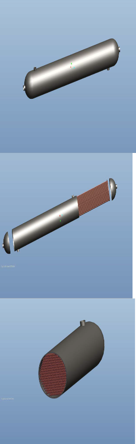
3DMODEL OF SHELL AND TUBE CONDENSER IN PRO-E SOFT WARE
IJSER © 2014 http://www.ijser.org
International Journal of Scientific & Engineering Research, Volume 5, Issue 7, July-2014 1191
ISSN 2229-5518
5. RESULT ANALYSIS
As a part of solution we suggest the firm to install a shell and tube type condenser.
This section thus contains:-
1. Cost of the shell and tube condenser
2. The reduction in fuel consumption in terms of money
5.1 Cost of the shell and tube condenser
The cost of shell and tube condenser including the
material and manufacturing cost =  91,000 [Cost analysis-Ref. “Narmada Industries”]
5.2 The reduction in terms of money
• Amount of heat energy required to convert the tap water (35ºC) into steam at
3.5 bar pressure is,
Q tap water = m Cp ∆T
= 4500 x 4.187 x (138.8 – 35)
= 543.26 kJ/s
• Amount of heat energy required to convert the condensed hot water (70ºC) into steam at 3.5 bar pressure is,
Q condensed water = m cp ∆t
= 4500 x 4.187 x (138.8 – 70)
= 360 kJ/s
• The reduction in energy consumption is shown below:-
∆Q = Q tap water – Q
condensed water
= 543.26 - 360
= 183.6 kJ/s
• Calorific value (C.V.) of natural gas (used in the company)
= 43000 kJ/ m3
• So the saving of fuel in terms of m3 / hr
= ∆Q / C.V.
= 660960 / 43000
= 15.37 m3 / hr
• Cost of 1 m3 natural gas =  24 / m3
• Supply of natural gas to boiler per hour =
80 m3/ hr
• Percentage of reduction in natural gas consumption per hour
= (saving of natural gas /
natural gas consumption) x 100
= (15.4 / 80) x 100
= 19.25 %
• Steam production cost =  7.5 / kg So due to the reduction in fuel consumption there will be reduction in cost for generation of the steam.
• So new steam generation cost
= 7.5 - [7.5 x (19.25/100)]
= 7.5 - 1.44
IJSER © 2014 http://www.ijser.org
International Journal of Scientific & Engineering Research, Volume 5, Issue 7, July-2014 1192
ISSN 2229-5518
= 6.06  /kg
/kg
• So we can see that steam generation cost is reduced from  7.5 to 6.06 / kg
• Thus from the above section we can say
that the cost of condenser is  91000 and by installing it we can reduce the cost of generation of steam from
  7.5 to
  6.06 per kg.
6. CONCLUSION
As proposed earlier, if a condenser is designed to condense the steam instead of allowing it to be wasted then following benefits can be drawn out of it.
• GENERAL BENEFITS
1) Wastage of steam can be prevented.
2) Since the surrounding temperature increases due to the steam, it becomes difficult to work around that area. Hence if that steam is used this problem can also be eliminated.
3) Because of disposing such high temperature steam in the open environment the % of oxygen (O2) in the atmosphere decreases. Instead of it if the steam is reused, the environmental damaged is minimized.
4) The instruments like pipe, valve, pump, etc., surrounding the wastage area can be prevented from deteriorating.
5) The storage problem that occurs in the Effluent treatment plant (E.T.P.) due to the wastage of the steam is eliminated.
6) If the steam is reused then its reaction with the waste material in sewage line and increase in the chemical of demand (cod) is prevented.
• FINANCIAL BENEFITS
1) The cost of producing the steam from the boiler decreases, as the consumption of the fuel for generation of the steam is reduced. Also the cost of installing a condenser is less than the total amount saved due to less consumption of fuel.
2) The cost of more new soft water for the production of steam decreases as the condensed steam so obtained acts as pure (soft) water.
IJSER © 2014 http://www.ijser.org