• High turbine RPM.
• Higher O&M costs.
• Lower operational availability.
International Journal of Scientific & Engineering Research, Volume 3, Issue 10, October-2012
ISSN 2229-5518
1
Waste Heat Recovery System by Using an
Organic Rankine Cycle (ORC)
Md. A. A. Mamun, Subrato Biswas
Abstract— Though the concept of Power Plants based on the Organic Rankine Cycle (ORC) is the new technology in Bangladesh, it can play a significant role to produce power from various heat sources when other alternatives were either technically not practical or not ec o- nomical. These power plants in sizes from 300 kW to 130 MW have demonstrated the maturity of this technology.[6] The cycle is well adapted to low moderate temperature heat sources such as waste heat from industrial plants. This paper represents the feasibility of ORC based power plant in Bangladesh which has been suffering from energy crisis and unable to meet the present demand. The ORC technol- ogy is applicable to heat recovery of steel mills, rerolling mills, cement plants, and offers significant advantages over conventional steam bottoming cycles. One such system, the 2.630 MW Power Plant is now under analysis forecasts at Rahim Steel Mill in Bangladesh. [2] The environmentally friendly power plant is the first to be installed in these types of industries.[2]
Key Words— Bangladesh, Gas Engines, Organic Rankine cycle,Organic fluid,Steam turbine,Steel Mill, Waste Heat Recovery.
—————————— ——————————
HERE are numerous steel plants in Bangladesh where the utilization of engine exhaust is either not possible or not required and this unused heat is lost .The ORC heat re- covery system at the Rahim Steel Plant in Bangladesh is the first of such systems will be supplied to the Steel industry. This environmentally friendly plant will recover the unused engine exhaust heat and will generate 2.630 MW of electricity on a continuous basis, displacing large amount of CO2 yearly, without interfering with the steel production process.[1] There are 8x 3.8 MW capacity gas engines at Rahim steel where a single unit’s exhaust gas flow rate 20770 kg/hr, exhaust tem- perature 479C. For a single unit 1578023 kcl/hr heat will recov- er from this plant. Considering whole eight units, it will turn into 12624180 kcl/hr.[1] If we will not recover the heat, the an- nual loss to be attributed to unused exhaust heat is million taka; a very significant expense for lost energy. The preferred approach to overcome this economically unsatisfactory situa- tion is to use the waste heat for the generation of electrical power. In the past some steel plant operators have installed waste heat steam boilers in their plants and have utilized the process heat to operate a steam turbine generator set. The con- ventional steam technology has some drawbacks. In particu- lar, with respect to stable steam turbine operation due to the high moisture content in the turbine exhaust and pinch point interference problems in the boiler. To overcome this draw- back, instead of using water an organic fluid will be used such as ammonia, hydrocarbons i.e. iso-pentane, iso-octane, toluene
or silicon oil, etc, instead of water.
————————————————
Subrato Biswas is currently working in Department of R&D(project),Dana Engineers International Ltd,Dhaka,Bangladesh. Former student in De- partment of Electrical & Electronic Engineering, Stamford Universty Bangladesh, Dhaka, Bangladesh. PH-+8801717862524.
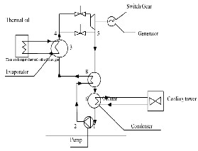
The heat contained in the exhaust gas is transferred indirectly via a thermal oil circuit or directly to the ORC plant. The ORC plant produces electricity and low temperature heat through a closed thermodynamic cycle which follows the principle of the Organic Rankine Cycle (ORC). In the ORC process, de- signed as a closed cycle, the organic working medium is pre- heated in a regenerator and in a pre heater, and then vapor- ized through heat exchanger with the hot source. The generat- ed vapor is expanded in a turbine that drives an asynchronous generator. Leaving the turbine, the organic working medium (still in the vapor phase) passes through the regenerator that is used to pre heat the organic liquid before vaporizing, there- fore, increasing the electric efficiency through internal heat recovery. The organic vapor then condenses and delivers heat to the cooling water circuit. After the condenser, the working medium is brought back to the pressure level required (for turbine operation) by the working fluid pump and then pre- heated by internal heat exchange in the regenerator. The low temperature heat is normally discharged to a thermal user or to the atmosphere. In this specific project, as per customer re- quest, we have considered to discharge the low temperature heat through an air condenser system.
The following blocks diagram shows the main components of the ORC based heat recovery system
E-mail: shuvorulez@gmaill.com
IJSER © 2012
International Journal of Scientific & Engineering Research, Volume 3, Issue 10, October-2012
ISSN 2229-5518
2
• High turbine RPM.
• Higher O&M costs.
• Lower operational availability.
Fig.1 ORC Power plant for Engine Heat Recovery.
The operation of the ORC plant is fully automatic in normal operating conditions as well as in shut down procedures without any need of supervision personnel. In case of faulty conditions, the ORC plant will be switched off automatically and separated from the thermal oil circuit and from the elec- trical grid. The ORC module is normally designed to automat- ically adjust itself to the actual operating conditions: variations on exhaust gas temperatures and flows (in reasonable span times) will not affect the functionality of the system (but just the power output).
The main difference between organic fluids and water is the lower evaporation energy of the former, so less heat is needed to evaporate the organic fluid. The evaporation of organic flu- ids usually takes place at lower temperature and pressure. The thermodynamic and chemical characteristics of these fluids no longer require superheating.
• Lower temperatures/pressures.
• Part load operation down to about 10%.[3]
• High efficiency at part load.
• Simple starts and stops procedures.
• No on-site operator needed.
• No erosion of turbine blades, so need for turbine overhauls.
• Low turbine RPM.
• Low O&M requirements.
• High availability (98%).[3]
• Higher temperatures and pressures.
• Generally NOT RECOMMENDED operate below 25%
load.[3]
• Lower part load efficiency.
• Slow start up.
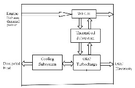
The project under analysis forecasts the erection of a 2.63 MWe (gross) waste to energy power plant.[1] As stated previously, the ORC technology could be a very efficient and flexible solu- tion for this project. An ORC power plant is an integrated sys- tem that produces electricity from thermal energy. Fig. 2(a re- peat of Fig. 1) provides a representative block diagram of an ORC power plant for engine heat recovery. Thermal energy contained in the hot engine exhaust (known as the source thermal power) is captured by a waste heat oil heater (WHOH) and transferred to the ORC turbo generator using a closed loop thermal oil subsystem.
Fig. 2 ORC Power plant for Engine Heat Recovery.
The ORC turbo generator converts approximately 20% of the captured thermal power into electric power. [3] A closed loop cooling subsystem removes the balance of this thermal power from the cycle and typically dissipates it to the envi- ronment. The electrical power can be delivered to the substa- tion to meet the customer’s demand. As indicated by the quan- tities passing across the boundaries, the ORC power plant has three primary process interfaces:
1. Thermal power must be provided.
2. Electricity must be used.
3. Heat must be dissipated
In this project, a heat exchanger, also known as a waste
heat oil heater (WHOH), is located in the thermal source
stream and thermal oil is pumped through it to the turbo gen-
erator.
Thermal oil heat transfer fluids and systems are highly
developed, reliable products; here we are using Exxon Mobil
as thermal oil heat transfer fluid. This intermediate heat
transfer approach provides great power plant layout flexibil-
ity, allowing significant separation between the thermal power
source and the ORC turbo generator [more than 100 m (330
[3]
• Requires on-site operator.
ft)].
This feature is particularly beneficial for this project be-
• High maintenance costs due to corrosion of turbine blades /
casing.
cause multiple thermal sources (e.g., multiple engines) are in
the application. Also, because the hot thermal source is not
transported into the ORC turbo generator, nor is the ORC
IJSER © 2012
International Journal of Scientific & Engineering Research, Volume 3, Issue 10, October-2012
ISSN 2229-5518
3
working fluid transported into the WHOH, the working fluid is not exposed to very high temperatures and the consequent thermal stability issues. The total volume of working fluid is also minimized.
The thermal oil subsystem contains a control valve to limit
the maximum input thermal energy to the level required by
the ORC turbo generator to produce the rated electrical power.
Signals from the ORC turbo generator to the control valve ac-
tuator command a position change to satisfy this criterion. The
control valve position is returned to the ORC turbo generator
controller for confirmation. If the maximum temperature of
the thermal source exceeds the use temperature of available
oils, a means to cool the oil (e.g. radiator) or to bypass the
WHOH is required for periods when the thermal source is
flowing but the turbo generator is off line (i.e. not removing
heat from the oil).Considering the characteristics of the fore-
casted power plant, the suitable ORC solution is the employ-
ment of one Turboden 30 –HR is being selected; in the table 1
the performance of the unit, data for designing of Waste Heat
Recovery Exchanger Thermal Oil Heater are given.
Table 1.[1-3]
(*) Net of ORC internal consumption (mainly feed pump). No external consump- tion are included (i.e. thermal oil system, heat dissipation system, etc).
By considering thermal losses 1% for the eight units, the gross
ORC active electric power can be achieved (+/10%) 2.630
MWe.[1]
For the cogeneration of industrial waste, the use of ORC offers some potentiality. As the cost of energy increases day by day, the use of organic Rankine cycles for effective energy utiliza-
tion can be expected to become more important in developing
IJSER © 2012
International Journal of Scientific & Engineering Research, Volume 3, Issue 10, October-2012
ISSN 2229-5518
4
countries like Bangladesh. ORC has demonstrated advantages
over conventional steam turbine and large amount of power can be achieved in gas engine power plants through enhanced waste-heat recovery while providing distinct cost and envi- ronmental advantages.
The authors are gratefull to the management of Dana Engi- neeris International ltd, Banani, Dhaka, Bangladesh for the continuous support in this project and special thanks to Mo- hammad Zahidul Karim Razib, Deputy manager (Project). The authors would also like to extend their gratitude to Professor Dr. Mohammad Mashud, Head of Mechanical Engineering Department, Khulna University of Engineering and Technolo- gy, Bangladesh for careful reading and providing thoughtful comments.
[1] Dana Engineers International Limited,Banani,Dhaka,Bangladesh
[2] Rahim energy waste heat recovery project, Dhaka, Bangladesh
[3] Turboden,a Pratt & Whitney Power Power System Company
[4] Uri Kaplan, ORMAT Technologies, Inc, (November 2007), ’’Advance
Organic Rankine Cycles in Binary Geothermal Power Plants’’
[5] B.Vanslambrouck, I.Vankeirsbilck, S.Gusev,M. De Paepe.’’ Turn waste heat into electricity by using an Organic Rankine Cycle’’, pp. 1-14,
2nd European Conference on Polygeneration – 30th March-
1stApril,2011–Tarragona,Spain,Available- http://www.orcycle.be/publicaties_bestanden/Paper1_2nd%20ECP%20OR C_final.pdf
[6] Hong Guang Zhang, En Hua Wang, Ming Gao Ouyang, Bo Yuan Fan,’’Study of Parameters Optimization of Organic Rankine Cycle (ORC) for Engine Waste Heat Recovery’’, Advanced Materials Re- search (Volumes 201 - 203),pp 585-589,available at http://www.scientific.net/AMR.201-203.585
[7] Lucien Y. Bronicki, Chairman, ORMAT International Inc.‘’Organic Rankine Cycle Power Plant For Waste Heat Recovery’’, available at http://www.ormat.com/research/papers/organic-rankine-cycle-
power-plant-waste-heat-recovery
[8] ORCYCLE,’’Organic Rankine Cycle’’,available at http://www.orcycle.be/index.php/en/orctheorie
[9] Chris Nelson, ’’Exhust Heat Recovery’’,Research and Tecnolo- gy,Presentation for Cummins,May 21st ,2009,pp. 1-30
[10] GE Energy,’’ A novel waste heat recovery process that couples a gas engine to traditional organic Rankine cycle technology is boosting ef- ficiency at power generation sites. Sean Ottewell reports’’,Organic Rankine cycle technology boosts onsite power projects,available at http://www.engineerlive.com/PowerEngineer/Heat_Recovery/Organi
c_Rankine_cycle_technology_boosts_onsite_power_projects/22173/
IJSER © 2012