International Journal of Scientific & Engineering Research, Volume 4, Issue 12, December-2013
ISSN 2229-5518
1410
Aouchenni Ounissa, Aouzellag Djamal and Lahaçani Aouzellag
Narimen
Mastery of Renewable Energy Laboratory, Department of Electrical Engineering, Faculty of Technology. University A. Mira of Bejaia, Algeria. aouchenni.ounissa@gmail.com aouzellag@hotmail.com
High penetration of wind energy into the networks may introduce stability and power quality problems due to the
fluctuating nature of the wind and the increasing complexity of the power system. This paper describes a novel approach to
voltage control for radial electrical distribution networks with connected wind farm using fuzzy supervisory control (FSC). A
control strategy of the inverter coupling a wind farm with the
electrical network will be carried out, this inverter will be used as a static compensator (STATCOM). Through the
example of 14 nodes distribution network, this study proves
that the method is feasible. The results also show that this
control is suitable for regulate the desired power flows in a
power network and to provide the best voltage profile in the
system as well as to minimize the system transmission losses when inserting the wind farm in the electrical network.
Keywords: Voltage profile, distribution network, wind generation, STATCOM, compensation, power control, fuzzy control.
IJSER © 2013 http://www.ijser.org
International Journal of Scientific & Engineering Research, Volume 4, Issue 12, December-2013
ISSN 2229-5518
1411
The main problem regarding wind power systems is the major discrepancy between the irregular character of the primary source (wind speed is a random, strongly non-stationary process, with turbulence and extreme variations) and the exigent demands regarding the electrical energy quality: reactive power, harmonics, flicker, etc. Thus, wind energy conversion within the parameters imposed by the energy market and by technical standards is not possible without the essential contribution of automatic control [1-3]. Due to the intermittence and fluctuating nature of the wind, the power quality and stability of the network can be affected when high wind power integration is present. Therefore, high penetration
level of wind energy in to the power systems, which were build based on large synchronous generators, may lead to a convenient redesign of the power system [4-6]. The static synchronous compensator is a main member of the FACTS family of voltage source converter (VSC) based devices. It has been studied for many years, and is probably the most
widely used in power systems, especially used to improve voltage regulation as well as to increase loadability margin [7, 8]. In recent years,
fuzzy logic controllers (FLC) have been widely used for industrial processes owing to their heuristic nature associated with simplicity and effectiveness for both linear and nonlinear systems [9-11]. Therefore the popularity of PID and the advantages of FLC can be incorporated into a
controller to achieve high control performance. This incorporation of the
two controllers denoted as fuzzy supervisory controller (FSC) or fuzzy self tuning PID controller. It is a good idea to combine between the two controllers to overcome the limitation of a conventional PID control in nonlinear systems [12, 13]. Electrical distribution networks were not designed to deal with significant power injections from decentralized production (DP), therefore the anticipated proliferation of DP results in a number of network planning and operational challenges, including voltage control, protection issues, altered transient stability, bidirectional power flow and increased fault levels; voltage variation has been identified as one of the dominant effects [14]. As a result, a lot of papers such as [1], [2], [15], [16] and [17], discussed the problem of connection of DP in electrical networks, regulate the desired power flows and provide the best voltage profile. [1] Demonstrated the effect of wind energy generation in power systems due to the inherent characteristics of wind turbine (aerogenerator), which causes variations in system voltage.
IJSER © 2013 http://www.ijser.org
International Journal of Scientific & Engineering Research, Volume 4, Issue 12, December-2013
ISSN 2229-5518
1412
Therefore, a wind turbine requires high reactive power compensation. Flexible AC Transmission System (FACTS) device such as Static Compensator "STATCOM" is power electronic switches used to control the reactive power injection, there by regulating the bus voltages. The impacts of the integration of a wind generator in an electrical supply network on the voltage stability and on the powers forwarded in this network are presented in [2] where the solution of this problem is proposed by inserting a FACTS device which is the SVC at the place of integration of the wind generator for the voltage adjustment. Continuous expansion of electrical distribution network along with the increased installation of DP in medium voltage level, leads to increasing the short- circuit current at some points of the network. In order to use the potential capacity of power generation, the available radial electrical distribution
system should be modified to a loop or a meshed configuration, this idea is developed in [15, 16] Looping the radial network has many benefits such as voltage regulation, loss minimization and congestion avoidance. In [17] network constrained setting of voltage control variables based on probabilistic load flow techniques is presented. The method determines constraint violations for a whole planning period together with the probability of each violation and leads to the satisfaction of these constraints with a minimum number of control corrective actions in a desired order. The method is applied to define fixed positions of tap- changers and reactive compensation capacitors for voltage control of a realistic study case network with increased wind power penetration. In this paper, a novel approach to voltage control for radial electrical distribution networks with connected wind farm is introduced. A reliable control strategy for inverter coupling a wind farm to the network is developed in order to ensure the stability of the system, regarding power quality and voltage level; this inverter is exploited for the active power transit from the wind farm to the network and for voltage regulation and maintaining it within the limits at the connection of this farm and to regulate the power flows in a power network.
The term “power quality” in relation to a wind turbine describes the electrical performance of the wind turbine electricity generating system. The main influences of a wind turbine on the power and voltage quality are voltage changes, fluctuations leading to flicker and harmonics for
IJSER © 2013 http://www.ijser.org
International Journal of Scientific & Engineering Research, Volume 4, Issue 12, December-2013
ISSN 2229-5518
1413
wind turbines with power electronics. The flickers caused by wind fluctuations may be of concern in low-voltage transmission lines connecting to the grid. The voltage drop related to power swing is small in high-voltage lines because of the small current fluctuation for a given wind fluctuation [1].
2.1 VOLTAGE REGULATION
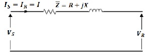
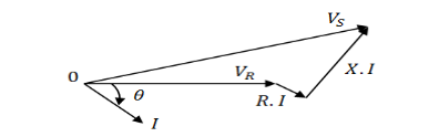
To develop a good, qualitative understanding of the need for reactive- power control, let us consider a simple case of a transmission line. Figure1 shows such a network with its parameters, as well as a phasor diagram on figure 2 showing the relationship between voltages and currents [1, 18, 19].
FIG. 1 – one-line diagram of an AC power system
FIG. 2 – phasor diagram for inductive load
It is clear that between the sending and the receiving end voltages, a magnitude variation, as well as a phase difference, is created. Voltage regulation of the transmission line may be defined as [18]:
IJSER © 2013 http://www.ijser.org
International Journal of Scientific & Engineering Research, Volume 4, Issue 12, December-2013
ISSN 2229-5518
1414
������� ������� �������𝑖�� =![]()
𝐼 (� cos 𝜃 ± � sin 𝜃)
��
× 100 1
Where:
�� : Sending end, voltage/phase;
�� : Receiving end, voltage/phase;
𝐼 : Line current, A;
�: Resistance, Ω /phase;
�: Reactance, Ω/phase;
𝜃 : Power factor angle, degrees.
The voltage drop in line can be writing in an approximate way as:
�� + ��![]()
∆� =
��
(2)
� and � respectively are the active and reactive powers flow on the line.
For the high-voltage lines, � ≥ 10. � the expression (2) can thus be
simplified:![]()
��
∆� =
��
(3)
Thus ∆� depends on reactive power flow on the line.
2.2 STRUCTURE AND OPERATION OF STATCOM
The Static Synchronous Compensator (STATCOM) is a shunt device of the Flexible AC Transmission Systems (FACTS) family using power electronics to control power flow and improve transient stability on power grids. The output current of this controller is adjusted to control either the nodal voltage magnitude or reactive power injected at the bus. STATCOM consists of one VSC with a capacitor on a DC side of the converter and one shunt-connected transformer. The reactive power exchange of STATCOM with the AC system is controlled by regulating the output voltage amplitude of VSC. If the amplitude is increased above that of the AC system, the current flows through the shunt transformer from the STATCOM to the AC system, and the device generates reactive power (capacitive). If the amplitude is decreased to a level below that of
IJSER © 2013 http://www.ijser.org
International Journal of Scientific & Engineering Research, Volume 4, Issue 12, December-2013
ISSN 2229-5518
1415
the AC system, then the current flows from the AC system to STATCOM
[6, 7, 19]. The equivalent circuit of the system is shown in figure 3.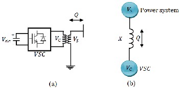
FIG. 3–Operating Principle of the STATCOM: (a) STATCOM connection diagram; (b) equivalent circuit
Figure 3 shows the transfer of the active and reactive powers between the
sources �� and �� . �� represents the system voltage to be controlled and
�� is the voltage generated by the VSC. The power relations are described
by:
� = �� �� sin /� (4)
� = �� (�� − �� cos )/� (5)
Where:
�� : The voltage generated by the centralized source;
�� : The voltage generated by the VSC;
�: Line reactance;
: Phase angle of �� with respect to �� ;
The amount of reactive power is given by:
� = (�� �� − �� )/� (6)
In our case of study, <0 and active power P≠0.
The capacitor is used to maintain dc voltage to the VSC, which itself
keeps the capacitor charged to the required levels.
IJSER © 2013 http://www.ijser.org
International Journal of Scientific & Engineering Research, Volume 4, Issue 12, December-2013
ISSN 2229-5518
1416
Fuzzy logic control (FLC), as one of the earliest applications of fuzzy sets and systems, has become one of the most successful applications. In fact, FLC has proven to be a successful control approach to many complex nonlinear systems or even non analytic systems. It has been suggested as an alternative approach to conventional control techniques in many cases. The fuzzy control algorithm consists of a set of heuristic control rules, and fuzzy sets and fuzzy logic are used, respectively, to represent linguistic terms and to evaluate the rules. The basic structure of a fuzzy control system consists of four conceptual components: knowledge base, fuzzification interface, inference engine, and
defuzzification interface [11, 20, 21]. Figure 4 shows the block diagram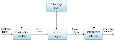
oIf a fuzJzy control sySstem. ER
FIG. 4–Basic structure of fuzzy control systems
The knowledge base contains all the controller knowledge and it comprises a fuzzy control rule base and a data base. The data base is the declarative part of the knowledge base which describes definition of objects (facts, terms, concepts) and definition of membership functions used in the fuzzy control rules. The inference engine is a reasoning mechanism which performs inference procedure upon the fuzzy control rules and given conditions to derive reasonable control actions. It is the central part of a fuzzy control system. The fuzzification interface (or fuzzifier) defines a mapping from a real-valued space to a fuzzy space, and the defuzzification interface (or defuzzifier) defines a mapping from a fuzzy space defined over an output universe of discourse to a real-valued space. The fuzzifier converts a crisp value to a fuzzy number while the defuzzifier converts the inferred fuzzy conclusion to a crisp value [11].
IJSER © 2013 http://www.ijser.org
International Journal of Scientific & Engineering Research, Volume 4, Issue 12, December-2013
ISSN 2229-5518
1417
Fuzzy control methodology is considered as an effective method to deal with disturbances and uncertainties in terms of ignorance and ambiguity. Fuzzy PID controller combining fuzzy technology with traditional PID control has become the most effective domain in artificial intelligence control [10, 11]. Figure 5 shows the PID control system with fuzzy control as supervisory controller.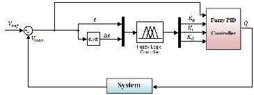
IJSFIG. 5– Fuzzy supeErvisory control R
The FSC has the form of PID control but the three parameters of PID
control are tuned using fuzzy controller based on the error and change of error as inputs to FLC. The inputs to PID controller are the error signal and the outputs of FLC. The output of PID controller fed [14-16] was obtained as shown in Figure 6 [12].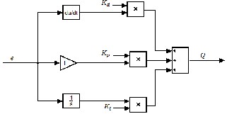
FIG. 6– Structure of fuzzy-PID controller
IJSER © 2013 http://www.ijser.org
International Journal of Scientific & Engineering Research, Volume 4, Issue 12, December-2013
ISSN 2229-5518
1418
As mentioned of fuzzy controller has two inputs �(�) and 𝛥�(�)
according to the following relations:
� � = ���� − ���� (�) (7)
𝛥� � = � � − � � − 1 (8)
The output fuzzy logic controller are �� , �� ��� �𝑖 .
Where:
�� Proportional factor;
�� Differential factor;
�𝑖 Integral factor.
5I. INVJERTER CSONTROL STREATEGY R
The essential part for well-performance of controller in inverter is the
voltage detection circuit. Voltage must be detected fast and corrected. The voltage disturbance detection method is based on the error between the
reference voltage magnitude ���� imposed equal to 10kV and voltage magnitude measured ���� on the network. The controller system is
presented in figure 7.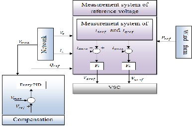
FIG. 7– Control block-diagram
IJSER © 2013 http://www.ijser.org
International Journal of Scientific & Engineering Research, Volume 4, Issue 12, December-2013
ISSN 2229-5518
1419
The three-phase supply voltage is transformed from ��� to ��� frame
using Park transformation. Phase Locked Loop (PLL) is used to track
supply voltage phase. The output of the PLL ( Ѳ = 𝜔 ��) is used to
compute the direct-axis and quadrature-axis components of the AC three-
phase voltage and currents (labeled as ��� , ��� or 𝐼�� , 𝐼�� on the
diagram represented on the figure 7) [22].
Where:![]()
�� = ��� 2 + ��� 2 (9)
When voltage drop or overvoltage is detected, the inverter switches into
active mode to react as fast as possible to inject or to absorb a quantity of
reactive power ���� in order to provide the best voltage profile in the
system as well as to minimize the system transmission losses. Therefore
the injection reactive power is generated according to the difference between the reference voltage and the measured voltage and it is applied to the VSC to produce the preferred voltage profile, using the voltage control based on fuzzy supervisory controller. The reference active power
���� is imposed equal to the power generated by wind farm. The active
and reactive powers forwarded are given by equations 10 and 11
respectively.
� = ��� 𝐼�� + ��� 𝐼�� (10)
� = ��� 𝐼�� − ��� 𝐼�� (11)
Park components of the reference currents are given by equations 12 and
13 [12].
𝐼���� =
𝐼���� =![]()
���� ��� + ���� ���
��� 2 + ��� 2![]()
���� ��� − ���� ���
��� 2 + ��� 2
(12) (13)
Where:
𝐼���� , 𝐼���� : Park components of the reference currents;
����� , ����� : Park components of the reference voltages;
���� , ���� : Active and reactive powers reference;
IJSER © 2013 http://www.ijser.org
International Journal of Scientific & Engineering Research, Volume 4, Issue 12, December-2013
ISSN 2229-5518
1420
��� , ��� : Park components of �� ;
���� : Voltage measured.
The electrical distribution network, which is used as a case study for simulation results is shown in figure 8.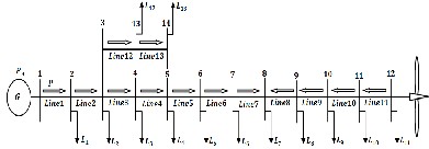
FIG. 8– Diagram of the studied network
As it can be illustrated in figure 8 the electrical study network is 10 kV
with 14 nodes, 13 sections and 13 fixed loads. The system data is given in Table 1 and 2. A wind farm is considered to be connected to the distribution network to bus 12; this wind farm will generate to the
network a power ��𝑖�� at an integration rate between 25% and 35%. The
power of this wind farm shown in Figure9 is chosen fluctuating form in
order to illustrate its influence on the network variables, i.e. voltage and powers.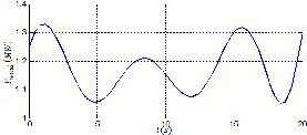
FIG. 9– Active power generated by wind farm
IJSER © 2013 http://www.ijser.org
International Journal of Scientific & Engineering Research, Volume 4, Issue 12, December-2013
ISSN 2229-5518
1421
Table 1: load data
TIable 2J: line data SER
In order to study the impact of the integration of the wind farm in electrical network. We will treat three cases of studies:
Network without wind farm; Integration of the wind farm;
Network with wind farm and compensation.
IJSER © 2013 http://www.ijser.org
International Journal of Scientific & Engineering Research, Volume 4, Issue 12, December-2013
ISSN 2229-5518
1422
7.1 NETWORK WITHOUT WIND FARM
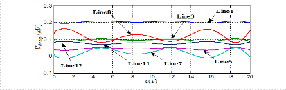
In first case, we will study only the electrical distribution network, without the wind farm and without compensation to evaluate power losses and voltage drops in the lines. Figure 10 presents the voltage magnitudes
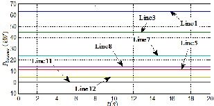
�� at the buses. Figures 11 and 12 show the evolution of the active
��𝑖��� and reactive ��𝑖��� powers forwarded in lines respectively. Figure
13 shows the evolution of the active ������� powers forwarded in lines and
figure 14 shows the voltage drops ����� in lines. According to the results
of simulation, one can observe high power losses. These losses are caused
mainly by resistance of conductors, where ‘Joule’ losses occur. And we can also observe high voltage drops in the lines. We know that the voltage drops are a consequence of the increased loading, increased transmission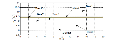
losses and the reactive power transported over a long distance. The highest voltage drop is recorded in bus 12, and is equal to the sum of voltage drops of all lines from the source up to this bus. Wind farm connected to network is one of the solutions used to solve the voltage drop problem and power losses through producing power at this location of the deficit.
FIG. 10– Voltage magnitudes at buses before integration of wind farm
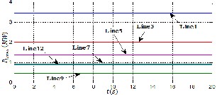
FIG. 11– Active powers flow on the lines
IJSER © 2013 http://www.ijser.org
International Journal of Scientific & Engineering Research, Volume 4, Issue 12, December-2013
ISSN 2229-5518
1423
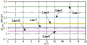
FIG. 12– Reactive powers flow on the lines
IJSER
FIG. 13– Active powers losses flow on the lines
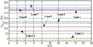
FIG. 14– Voltage drops in the lines
IJSER © 2013 http://www.ijser.org
International Journal of Scientific & Engineering Research, Volume 4, Issue 12, December-2013
ISSN 2229-5518
1424
7.2 INTEGRATION OF THE WIND FARM
To overcome the problem of voltage drops and power losses in the distribution network a wind farm is connected in bus 12. Figure 15 presents the voltage magnitudes at the buses, we observe that there is an improvement of the voltage level; however, this voltage is fluctuating form. Figure 16 shows the evolution of the active powers forwarded in lines, it can be seen that wind farm provides a capability to change the direction of power flow over lines 11, 10, 9 and 8 into the inverse direction. A significant improvement of the active power losses is noted in figure 17 showing active power Losses flow on the lines [16]. We can also see through figure 18 that the voltage drops are decreased. Figure 19
shows the evolution of active �� and reactive �� powers generated by the
source 𝐺. We note a significant reduction of the active power delivered by
the source 𝐺 ; therefore, the source is relieved thanks to this insertion.
Figure 20 presents the active powers provided by source and wind farm.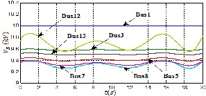
FIG. 15– Voltage magnitudes at buses before compensation
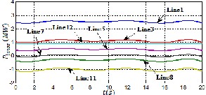
FIG. 16– Active powers flow on the lines
IJSER © 2013 http://www.ijser.org
International Journal of Scientific & Engineering Research, Volume 4, Issue 12, December-2013
ISSN 2229-5518
1425
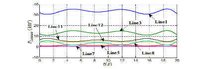
FIG. 17– Active powers Losses flow on the lines
IJSFIG. 18– Voltage dErops in the lines R
FIG. 19– Active and reactive power of the source
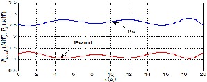
FIG. 20– Active power of the source and wind farm
IJSER © 2013 http://www.ijser.org
International Journal of Scientific & Engineering Research, Volume 4, Issue 12, December-2013
ISSN 2229-5518
1426
In order to solve the problem of voltage and power fluctuation caused by the power delivered by wind farm, compensation will be made via the inverter whose role is to provide reactive power necessary for regulating voltage and powers flow.
7.3 NETWORK WITH COMPENSATION
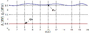
The results obtained show the contribution of the compensation for the voltage regulation on a network and powers flow. Figure 21 presents the evolution of the voltage magnitudes at the buses after compensation and we can see that the voltages became very stable. The active and reactive powers measured follow perfectly their references as show figures 22 and
23 respectively. Figure 24 representing the active power delivered by
wind farm at the bus 12 and reactive compensation power �� , clearly
shows the interest of the compensation, where the reactive power varies
according to the change of active power, for maintain better voltage profile in the electrical distribution network. Figure 25 shows the evolution of the active powers forwarded in lines.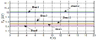
FIG. 21– Voltage magnitudes at buses after compensation
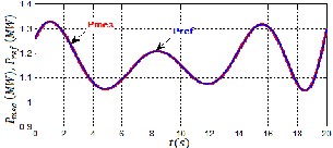
FIG. 22– Measured active power and its reference value
IJSER © 2013 http://www.ijser.org
International Journal of Scientific & Engineering Research, Volume 4, Issue 12, December-2013
ISSN 2229-5518
1427
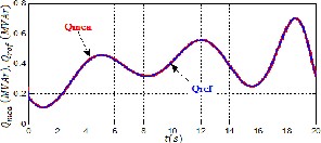
FIG. 23– Measured reactive power and its reference value
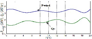
FIG. 24– Active power at the connecting node of wind farm and the reactive compensation power
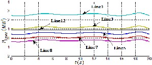
FIG. 25– Active powers flow on the lines
The penetration of wind energy into the network introduces stability and power quality problems due to the fluctuating nature of the wind. In this paper, voltage control in an electrical network as well as the problems induced by this kind of energy on the voltage profile are exposed. In this
IJSER © 2013 http://www.ijser.org
International Journal of Scientific & Engineering Research, Volume 4, Issue 12, December-2013
ISSN 2229-5518
1428
context, the objective was to carry out applications related to the improvement of the voltage profile via the inverter which was exploited, not only, for the transit of the active power of the wind farm towards the network, but also, it was used to provide or to absorb reactive power in order to stabilize the voltage at the connecting node of the farm and to thus maintain the voltage profile to the desired value. The results indicate that the proposed control works effectively.
[1] N. Aouzellag Lahaçani, D. Aouzellag and B. Mendil. Static compensator for maintaining voltage stability of wind farm integration to a distribution network. Renewable Energy 2010, 35:2476–2482. Science Direct, Elsevier.
[2] N.A. Lahaçani, D. Aouzellag and B. Mendil. Contribution to the improvement of voltage profile in electrical network with wind generator using SVC device. Renewable Energy 2010, 35: 243–248.
Science Direct, Elsevier.
[3] O. Aouchenni, N. Aouzellag Lahaçani and D. Aouzellag. Contrôle de tension de la production éolienne connectée au réseau de distribution. International Conference on Renewable Energy ICRE Bejaia: 2012.
[4] T. Ackerman, Wind Power in Power Systems. Royal Institute of
Technology Stockholm, Sweden: John Wiley & Sons, 2005.
[5] I. Munteanu, AI. Bratcu, N-A. Cutululis and E. Ceanga. Optimal control of wind energy systems. towards a global approach. London: Springer-
Verlag, 2008.
[6] RM. Mathur and RK. Varma. Thyristor-based FACTS controllers and electrical: transmission systems. John Wiley & Sons, 2002.
[7] Z. Yankui, Z.Yan, W. Bei and Z. Jian. Power injection model of
STATCOM with control and operating limit for power flow and voltage stability analysis. Electric Power Systems Research 2006, 76:1003–
1010. Science Direct, Elsevier.
[8] M.H. Haque. Damping improvement by FACTS devices: A comparison between STATCOM and SSSC. Electric Power Systems Research 2006,
76:865–872. Science Direct, Elsevier.
[9] X. Jian-Xin, H. Chang-Chieh and L. Chen. Parallel structure and tuning of a fuzzy PID controller, Automatica 2000, 36: 673–684.Science Direct, Elsevier.
[10] O. Karasakal, M. Guzelkaya,I. Eksin, and E. Yesil and T. Kumbasar.
Online tuning of fuzzy PID controllers via rule weighing based on normalized acceleration. Engineering Applications of Artificial Intelligence 2013, 26:184–197. Science Direct, Elsevier.
IJSER © 2013 http://www.ijser.org
International Journal of Scientific & Engineering Research, Volume 4, Issue 12, December-2013
ISSN 2229-5518
1429
[11] G. Feng. A Survey on Analysis and Design of Model-Based Fuzzy
Control Systems. IEEE Transactions on fuzzy systems, vol 14, NO. 5,
2006.
[12] A.Z. Alassar, I.M. Abuhadrous and H.A. Elaydi. Modeling and Control of 5 DOF Robot Arm Using Supervisory Control. 978-1-4244-5586-
7/10/$26.00, IEEE 2010.
[13] L. Wang, M. Tian and Yanping Gao. Fuzzy Self-adapting PID Control of PMSM Servo System. 1 -4244-0743-5/07/$20.00, IEEE 2007.
[14] T.P. Blanchett, G.C. Kember and R. Dubay. PID gain scheduling using
fuzzy logic. ISA Transactions 2000, 39: 317–325. Science Direct, Elsevier.
[15] H. Shi-Zhong, T. Shaohua, X. Feng-Lan, W. Pei-Zhuang. Fuzzy self- tuning of PID controllers. Fuzzy sets and systems 1993, 56: 37–46. Science Direct, Elsevier.
[16] H. B, Kazemian. comparative study of a learning fuzzy PID controller
and a self-tuning controller. ISA Transactions 2001, 40: 245–253. Science Direct, Elsevier.
[17] N.D. Hatziargyriou, T.S. Karakatsanis and M.I. Lorentzou. Voltage control settings to increase wind power based on probabilistic load flow.
Electrical Power and Energy Systems 2005, 27: 656–661. Science
Direct, Elsevier.
[18] D. Das. Electrical power systems. New Delhi: New Age International
Publishers, 2006.
[19] X-P Zhang, E. Handschin, M. Yao. Multi-control functional static synchronous compensator (STATCOM) in power system steady-state operations. Electric Power Systems Research 2004, 72: 269–78. Science Direct, Elsevier.
[20] C. C. LEE. Fuzzy Logic in Control Systems: Fuzzy Logic Controller- Part I. IEEE Transactions on systems. man, and cybernetcs. VOL. 20. NO. 2. 1990.
[21] C. C. LEE. Fuzzy Logic in Control Systems: Fuzzy Logic Controller-
Part II. IEEE Transactions on systems. man, and cybernetcs. VOL. 20. NO. 2. 1990.
[22] H. Ezoji, A. Sheikholeslami, M. Rezanezhad and H. Livani. A new control method for Dynamic Voltage Restorer with asymmetrical inverter legs based on fuzzy logic controller. Simulation Modelling
Practice and Theory 2010, 18: 806–819. Science Direct, Elsevier.
IJSER © 2013 http://www.ijser.org