International Journal of Scientific & Engineering Research, Volume 6, Issue 2, February-2015
ISSN 2229-5518
1367
Voltage Stability Enahncement using Static VAR Compensator (FC-TCR)
Romana Pradhan, M.Tech student,Electrical and Electronics Department,Sikkim Manipal Institute of Technology, Sikkim, India. Mohammed Nasir Ansari, Associate Professor,Electrical and Electronics Department, Sikkim Manipal Institute of Technology, Sikkim, India.
Abstract— One of the major concerns of power system stability is the voltage instability. The main reason behind the voltage instabili- ty is the deficit of the reactive power in the system. The effect of Static VAR Compensator (SVC) in static voltage stability enhancement will be studied in this paper. Improving the systems voltage by increasing the reactive power handling capacity of the system by using SVC during a large disturbance is the area of study. The IEEE-14 bus system is used as the test system for the study. The simulations are carried out by using MATLAB/PSAT software. The simulation results show the effectiveness of SVC to improve the voltages when connected to the system.
Index Terms— FACTS, SVC,Voltage Stability, PSAT.
—————————— ——————————
1 INTRODUCTION
Demand is rising and the modern society would cease to func- tion without access to electricity. As the volume of power transmitted and distributed increases, so do the requirements for high quality and reliable supply [1]. Thus the Transmission networks of present power systems are becoming progressive- ly more stressed because of increasing demand and limitations on building new lines. Making existing lines as well as new ones more efficient and economical becomes a compelling al- ternative [1].
Present day power systems are being operated closer to their
stability limits due to economic and environmental con- straints. Maintaining a stable and secure operation of a power system is therefore a very important and challenging issue.
Voltage instability has been given much attention by power system researchers and planners in recent years, and is being regarded as one of the major sources of power system insecur- ity [2].
The main factor causing voltage instability in a power system is
lack of reactive power in the system. The solution to this problem is Flexible AC Transmission System (FACTS), which involves up-gradation of the transmission lines by installing FACTS de- vices. Since blackouts in the majority of cases are caused by a deficit of reactive power, FACTS comes into the picture as a remedy in a natural way [3].
Voltage stability problems arising from a large disturbance categorized under large disturbance voltage stability are a major concern in power systems stability [3]. This is the study made in this paper. Large-disturbance voltage stability refers to the system’s ability to maintain steady voltages following large disturbances such as system faults, loss of generation, or, circuit contingencies [3].
The voltages at various points after such a disturbance may
reach the pre-disturbance values or not, leading to voltage sag
at certain points. Using FACTS controllers one can control the
variables such as voltage magnitude and phase angle at cho-
sen bus and line impedance where a voltage collapse is ob-
served [4].
3 Problem Statement
Voltage stability is the ability of a power system to maintain
acceptable voltages at all buses in the system under normal
conditions and after being subjected to a disturbance [5]. It is the main factor that limits the amount power transfer in a sys-
tem. Voltage instability typically occurs in the system which is heavily loaded, faulted or has reactive power shortage [5]. The large disturbance considered here is a three phase fault, typi- cally a transmission line loss or a transmission line outage. The fault is observed at the transmission line between bus2 and bus 5 in a 14 bus system with a fault time of 1.2 seconds and the fault clearing time of 1.209 seconds. Due to this fault there is a voltage sag in the number of buses namely bus 4, 5, 7, 9,
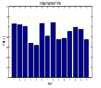
10,14. It is observed from the figure1 which shows the sag in the voltage magnitude profile of the buses when subjected to a large disturbance, which in this case is a transmission line out- age.
Fig1: voltage magnitude profile during three phase fault.
IJSER © 2015
http://www.ijser.org
International Journal of Scientific & Engineering Research Volume 6, Issue 2, February-2015
ISSN 2229-5518
1368
The idea behind this work is to improve the voltage magni- tude profile of the system and increase the maximum loading capacity by using reactive power compensation at the buses.
3 STATIC VAR COMPENSATOR
Static VAR compensator (SVC) is a shunt connected static elec- trical device. It acts as a generator or absorber of reactive pow- er. SVC has its output adjusted to exchange capacative or in- ductive current according to the requirement of the system. The main function of SVC is to regulate the voltage by provid- ing fast acting reactive power. They generate or absorb reac- tive power at its point of connection in the power system.
The basic structure of SVC is shown in figure 2. It can be seen
that the model of a SVC is represented by an inductor con-
nected in series to a bi-directional thyristor and a fixed capaci-
tor connected in parallel. Through a suitable coordination of
the capacitors and the thyristor controlled reactor (TCR), the
bus reactive power injected (or absorbed) by the SVC can be continuously varied in order to control the voltage or to main-
tain the desirable power flow in the transmission system [4]. The amount of current in the reactor can be varied by varying the delay angle of the thyristors. When the capacitive and in- ductive currents become equal, both the VARs cancel out and give zero VAR output, which indicates that there is no power exchange between the SVC and the AC system [6].
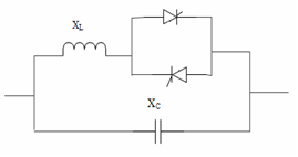
Fig 2: Structure of SVC
Figure 3 shows the V-I characteristics of SVC, which has a ca-
pacitive limit and an inductive limit. At the capacitive limit the
SVC becomes a shunt capacitor and at the inductive limit the
SVC becomes a shunt reactor.
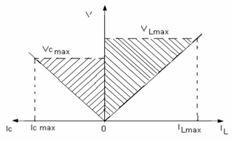
Fig 3: V-I characteristics of SVC.
4 TEST SYSTEM AND SOFTWARE
A standard IEEE 14 bus system as shown in figure 4 is used for the study. The test system consists of five generators and eleven PQ bus (or load bus) [7]. The simulations are done us- ing PSAT simulation software. PSAT is a power System Anal- ysis software, which has many features including power flow and continuation power flow [8]. Voltage stability of the test system is investigated using Continuation power flow, a fea- ture of PSAT. The figure 4 shows the PSAT model of IEEE 14 bus system.
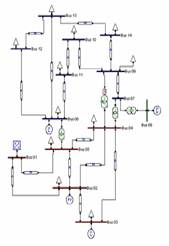
Fig 4: PSAT model of IEEE 14 bus system.
5 RESULT AND DISCUSSION
The power flow analysis using PSAT is run for the test systems and the voltage profile is obtained. The test systems are simulated for a base case of 100 MVA. The figure 5 shows the voltage mag- nitude profile of the 14 bus system for base case. Then a three phase fault is introduced in the system as discussed earlier, which is basically a transmission line outage. The figure 1 shows the voltage magnitude profile obtained after the fault has been intro- duced in the system.
IJSER © 2015
http://www.ijser.org
International Journal of Scientific & Engineering Research Volume 6, Issue 2, February-2015
ISSN 2229-5518
1369
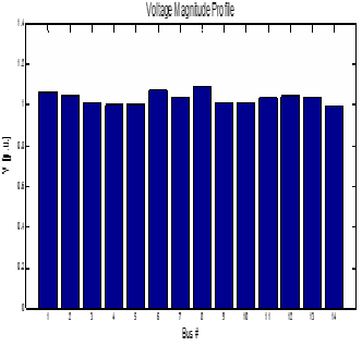
Fig 5: voltage magnitude profile of the 14 bus system for base case.
There is a considerable drop in the voltage magnitude in number of buses which is clear from figure 1 and figure 5. So we need to make reactive power compensation to improve the voltage profile at these buses by using SVC [2]. Thus it is re- quired to find out the best location of SVC. SVC is desired to be placed at the bus whose voltage has drastically fallen, which can be termed as the weakest bus in the system.
The weakest bus in the system is identified by the continua-
tion power flow analysis using PSAT. We identify the weakest
buses to be 4, 5, 9. The figure 6 shows the P-V curve for the
weakest three bus voltages.
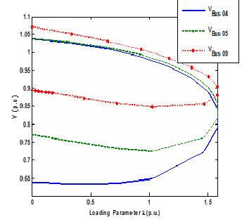
Fig 6: Nose curve of bus 4, 5 and 9.
Among these buses bus 9 has the weakest voltage profile.
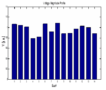
Thus the best location of SVC is at bus9.The SVC parameters used in this case is, XL = 0.7 and XC = 0.35 with the firing angle of 2.979 radians. It is expected that by placing SVC at this loca- tion there is a marginal increase in the bus voltages. The vol- tage profile for the system with SVC at bus 9 is shown in fig- ure 7.
Fig 7: voltage magnitude with SVC.
The following figure 11 similarly shows the improvement of
voltage at the weakest buses namely bus 4, 5 and 9 using SVC
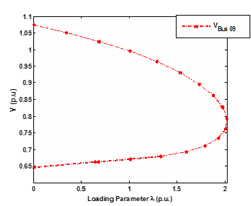
in the 14 bus system.
Fig 8: Nose curve of bus 9 with SVC.
We find the significant difference in the voltage profile at var-
ious locations in the above test systems before and after the placement of SVC indicating that it is effective in requirement
to improve voltage profile of an interconnected power system in case of an occurrence of large disturbance in the form of a 3 phase fault.
IJSER © 2015
http://www.ijser.org
International Journal of Scientific & Engineering Research Volume 6, Issue 2, February-2015
ISSN 2229-5518
1370
Table1: Voltage profile of IEEE 14 bus system with base case, with fault and with SVC at bus 9 in the system.
Bus no | Voltage (Base con- dition) | Voltage (Faulted condition) | Voltage (With SVC) |
1 | 1.06 | 1.06 | 1.06 |
2 | 1.045 | 1.045 | 1.045 |
3 | 1.01 | 1.01 | 1.01 |
4 | 0.99772 | 0.67802 | 0.84387 |
5 | 1.0024 | 0.72242 | 0.94127 |
5 | 1.07 | 1.07 | 1.07 |
7 | 1.0347 | 0.80401 | 0.93386 |
8 | 1.09 | 1.09 | 1.09 |
9 | 1.0111 | 0.66421 | 0.88387 |
10 | 1.0105 | 0.7506 | 0.89278 |
11 | 1.0346 | 0.89264 | 0.96056 |
12 | 1.0461 | 0.98627 | 1.0169 |
13 | 1.0362 | 0.94214 | 0.99906 |
14 | 0.99568 | 0.72689 | 0.88418 |
The graphical representation of the above table containing the voltage magnitude for different cases is shown in the figure 9.
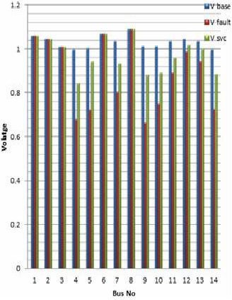
Fig 9: Voltage magnitude profile.
We observe that there is a significant difference in the voltage
profile at various buses in the above test systems before and after the placement of FACTS devices indicating that the SVC is effec- tive when it is required to improve voltage profile of an intercon- nected power system in case of an occurrence of large disturbance in the form of a 3 phase fault. Thus there is an overall enhance- ment in the voltage stability of the system.
6 CONCLUSION
FACTS device Static VAR compensator (SVC) is used for vol- tage stability enhancement. The test system which is the IEEE
14 bus system is studied and simulated using the continuation power flow analysis. The simulation results show a significant increase in the voltage profile at different buses by the place- ment of FACTS. This can be clearly observed from the nose curves and the voltage magnitude profiles. Thus FACTS are powerful devices that aid in the improve- ment of voltage. It also increases the system security and re- liability therefore contributing in solving many power system problems.
REFERENCES
[1] ABB ,”SVC, an insurance for improved grid system stability and reliabil
ity”.
[2] S. Chakrabati, Dept. of EE, IIT, Kanpur,”Notes on Power System Stabil-
ity”.
[3] Richa, Sh. Vivek Kumar, Sh. Kumar Dhiraj ,”Voltage instability and its prevention using facts controller”; International Journal of Engineering Re- search and Development, Volume 3, Issue 11 (September 2012).
[4] G Naveen Kumar and M Surya Kalavathi,” Reactive Power Compensation for Large Disturbance Voltage Stability using FACTS Controllers ”; IEEE
2011; page(s):164-167.
[5] Nimit Boonpirom and Kitti Paitoonwattanakij,” Static Voltage StabilityEn- hancement using FACTS”; The 7th International Power Engineering Con- ference IPEC/IEEE, Vol.2, pp.711-715,2005.
[6] Heinz. Tyll and Dr.Frank Schettler,”Power System Problems solved by FACTS Devices”. Power Systems Conference and Exposition, 2009. PSCE '09. IEEE/PES.
[7] Mehrad Ahmadi Kamarposhti and Mostafa AlinezhaD,” Comparison of
SVC and STATCOM in Static Voltage Stability Margin Enhancement”;
World Academy of Science, Engineering and Technology, vol:3 2009-02-
20.
[8] F. Milano, "Power System Analysis Toolbox," Version 1.3.4, Software and
Documentation, July 14, 2005.
[9] Kazemi H. Andami,” FACTS Devices in Deregulated Electric Power Sys- tems: A Review”; IEEE International Conference on Electric Utility De- regulation, Restructuring and Power Technologies 2014.
[10] C. A. Canlzares and Z. T. Faur, "Analysis SVC and TCSC Controllers in
Voltage Collapse," IEEE Trans. Power Systems, Vol. 14, No. 1, February
1999, pp. 158-165.
IJSER © 2015
http://www.ijser.org