International Journal of Scientific & Engineering Research, Volume 2, Issue 12, December-2011 1
ISSN 2229-5518
Vibration Based Condition Monitoring of
Rolling Mill
Vinod D.TIrpude, Jayant P.Modak, Girish D. Mehta
Abstract: All over the India, most of the processing industries are involved with rolling operations for steel and alloyed materials. To perform these operations, rolling mills are used. But maintenance of such rolling mills is a tedious job, because these rolling mills work under certain critical conditions such as frequent load variations, higher temperatures etc. Hence, every component bears load variations, which results in wear and tear of components. This causes frequent breakdowns of rolling mill components. Thus, it involves lot of maintenance cost, loss of production time, more number of workforces to perform maintenance action etc. One such rolling mill, which is situated in Hingna MIDC, Nagpur is taken as a case study in the present work. This rolling mill uses preventive and break-down maintenance strategies. But, these strategies seem to be inadequate.To reduce the losses, a new logic along with a new maintenance technique is suggested through this present work. This maintenance technique is nothing but “vibration based condition monitoring”, which is discussed with following articles.
Keywords: Bearing reactions, FFT Analyser, Fiber Pressuriser, Maintenance Strategy, rolling mill, vibration based condition monitoring ,vibration spectrum.
—————————— ——————————
1. INTRODUCTION
1.1 Present State of Art of Maintenance
Strategies Of Rolling Mill:
MAINTENANCE of plant and equipment is carried out to increase the availability and reliability [21]*, so that, it will continue to operate satisfactorily for the entire life- cycle of the equipment with required cost effectiveness. There are two main categories of maintenance strategies adopted in most of the rolling mills:
1) Break-down Maintenance
2) Preventive Maintenance
In ‚Breakdown Maintenance‛, one allows an operating machine component to run until it fails and then repair it in order to restore the same to an acceptable condition. It is not economical to use ‚Break-down Maintenance‛ as it increases down time cost, hazards and unscheduled outage; however it reduces the administrative shutdown steps, unnecessary outage and results in long run time.
[ ]* the number in the square bracket indicates the references which are at the end of the thesis.
The ‚preventive maintenance‛ is carried out at
predetermined intervals. It is planned in advance and normally requires a long shut down. Here the component is allowed to wear out or deteriorate within the life of the component and then replacement or repair is carried out at predetermined intervals. This is carried out for those units, where total cost of such work is substantially less than those of failure replacement/repair. The cost of preventive maintenance is high; it wastes production output and doesn’t include corrective or emergency maintenance.
In the present paper Rolling Mill -2 is considered. As this Rolling Mill is older therefore defects such as a) looseness of fasteners and belts, b) mis-alignment of parts, c) wear out of the components such as gear teeth, bushes, couplings and bearings are observed during inspection, which are frequently occurred. These defects are attended regularly. To prevent any outage, Vibration Based Condition Monitoring Technique seems as one another alternative approach.
2. AN APPROACH FOR A NEW MAINTE- NANCE STRATEGY FOR SUCH A ROLLING MILL:
In order to reduce the shut down period and down time cost, the predictive maintenance [6] is suggested. As it
IJSER © 2011 http://www.ijser.org
International Journal of Scientific & Engineering Research, Volume 2, Issue 12, December-2011 2
ISSN 2229-5518
is initiated as a result of knowledge of condition of
equipment for inspection and measurements, so it is called as Condition Based Maintenance or CBM. In this Condition Monitoring Technique, the plant is maintained just after some problem has arisen, but much before the possible break-down. The maintenance activity is directed towards curing a particular problem.
3. RELATIONS BETWEEN LOAD AND VIBRATION RESPONSE (A PROPOSED THEORY):
When a billet comes in contact with rolls, a
tremendous pressure on the rolls occurs. The billet is under the process of plastic deformation. During this plastic deformation, a high frictional resistance is offered by a billet on a roll, which offers a load torque on a roller shaft. This roller shaft is connected by the power transmission element such as gears, v-belts, couplings to the motor shaft (Kindly refer Figure1). The induced load torque is then transferred to the motor shaft via this power transmitting element. To overcome this load torque a motor generates additional driving torque, which is transferred again through power transmission element to the roller shaft. This action is continued for total rolling operation. The increased load is then sustained by each component of a rolling mill. Thus increased load in each component produces additional bearing reactions. This increased bearing reaction is then responsible for increase in vibration amplitude at respective frequency of a component. It means as bearing reaction increases conversely the amplitude will also increase.
4. ROLLING MILL:
A rolling mill 2 of this company uses an 800 HP motor, which is used to transmit the power to the rolling mill. Motor shaft S1 is rested on bearings B1 and B2. It is coupled with smaller pulley shaft S2 with the help of coupling C1. Smaller pulley shaft is placed on bearings B3 and B4. The power is transmitted from smaller pulley to bigger pulley with the help of 18 belts. The velocity ratio between smaller pulleys to bigger pulley is 1:2. Bigger pulley shaft S3 is placed on bearings B5 and B6. The flywheel is also placed on bigger pulley shaft S3. The shaft S3 is coupled to pinion shaft S4 inside the reduction gear box with the help of coupling C2. Pinion shaft S4 is rested on bearings B7and B9. The power is transmitted from shaft
S4 to gear shaft S5 with the help of pinion-gear
arrangement PE1-GE1. Gear shaft S5 is placed on bearings B8 and B10 inside the reduction gear box. On shaft S4, double helical pinion with 24 teeth and on shaft S5,a double
helical gear with 36 teeth are placed. The power is transmitted from shaft S5 to the rolling mill shaft S6 with the help of coupling C3. Shaft S6 is placed on bearings B11 and B12 inside main gear box. In this gear box three gear arrangements are provided. The main driving shaft S6 provides the power to other two driven roller shafts S7 and S8 with the help of pinion and gear arrangements PI2-GE2 and PI3-GE3.
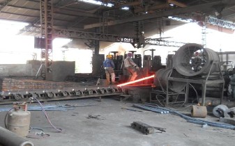
Figure 1: Pictorial view of hot rolling mill operation at the company
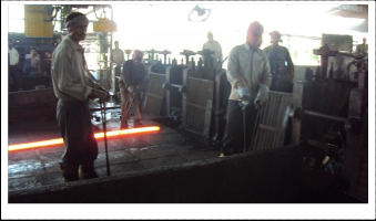
Figure 2: Pictorial view of hot rolling mill operation at the company
IJSER © 2011 http://www.ijser.org
International Journal of Scientific & Engineering Research, Volume 2, Issue 12, December-2011 3
ISSN 2229-5518
C2
F B6 B7
PI1
REDUCTION GEAR BOX FB MAIN GEAR
B5
S3
18
BELTS
S2
L
Y W H E E
L
S5
B8
BRG B2
B9
S4
B10
C3
S6
GE1
BOX
FIBERS
B4 B3
SMALLER
BRG B1
SHAFT S1
MOTOR
ROLLS ROLL STAND
PULLEY
COUPLING C1
FB-FIBER PRESSURISER
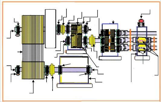
Figure 3: Schematics of Roll Mill at the company
5. FIELD DATA COLLECTION:
A systematic approach is adopted for the collection of field data. The methodology of collection of data, frequency calculations, measurement of amplitudes at these frequencies, measurement of load and speed from a field set up are nicely discussed through following articles.
5.1 Planning For Gathering Field Data:
In this rolling mill company, it is then decided to do the condition monitoring of rolling mill 2. The specifications of different components of this rolling mill are taken. It is planned that condition monitoring of the components should be carried out which gets failed intermittently. For this, the bearings are identified in such a way that, by the side of these bearings, the affected components are placed. These bearings are B7, B9 and B10, which are facing severe working conditions. At these bearings, vibrations are created not only because of the worn out conditions of the components but also each component imposes additional bearing reactions, which is in turn increases the vibrations.
It is also planned that at least 5 to 7 vibration spectrums should be taken in succession at each bearing one by one. This is because of space constraint and limited
time availability for each pass of the billet through the rolls, as the process of each pass will take only few seconds.
For taking vibration signatures, a FFT Analyzer [23] is used along with vibration pick-up i.e. accelerometer for sensing the vibrations.
The measurement of speed of the shaft is done with the help of tachometer. It is planned to carry out condition monitoring of the components by taking the vibrations spectrums in the order of following sequence: B10, B9 and B7.
5.2 Methodology For Collection Of Data:
For taking vibration data and other relevant parameters for the present investigation, the sequential methodology is used, which is discussed through following articles.
5.2.1 Collection of Vibration Spectrums:
The collection of vibration data i.e. vibration spectrums from different bearings require proper methodology, which is done as under:
IJSER © 2011 http://www.ijser.org
International Journal of Scientific & Engineering Research, Volume 2, Issue 12, December-2011 4
ISSN 2229-5518
Firstly the upper portion of bearing cap B10 is made available free from dirt and grease by cleaning it. Then an accelerometer is placed on it. By pushing a start button, vibration spectrums are captured. As the desired vibration spectrum is captured, same procedure is adopted for the next spectrums.
When the procedure of taking vibration spectrums is
going on, at the same time speed measurement is also carried out for each pass. This procedure runs for each reading. For Bearing B10, nine vibration signatures are taken. The above said procedure is also adopted for the bearings B9 and B7. Each spectrum denotes each pass of billet through the rolls at different loading conditions as well as for different timings.
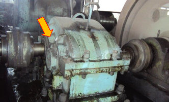
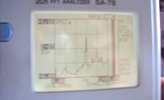
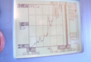
Figure 4 : Position of Bearing B10
Figure 5: Vibration Spectrum no.1 at Bearing B10 (Time- 12:32:27)
Figure 6: Vibration Spectrum no.2 at Bearing B10 (Time- 12:32:14)
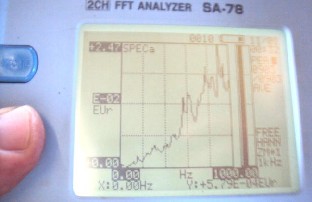
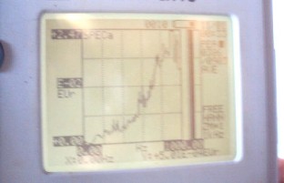
Figure 7: Vibration Spectrum no.3 at Bearing B10 (Time- 12:32:27)
Figure 8: Vibration Spectrum no.4 at Bearing B10 (Time- 12:33:24)
IJSER © 2011 http://www.ijser.org
International Journal of Scientific & Engineering Research, Volume 2, Issue 12, December-2011 5
ISSN 2229-5518
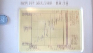
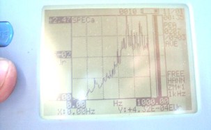
Figure 9: Vibration Spectrum no.5 at Bearing B10 (Time- 12:33:47)
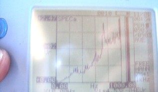
Figure 10: Vibration Spectrum no.6 at Bearing B10 (Time- 12:34:37)
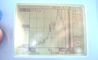
Figure 11: Vibration Spectrum no.6 at Bearing B10 (Time- 12:35:10)
Figure 12: Vibration Spectrum no.8 at Bearing B10 (Time- 12:35:33)
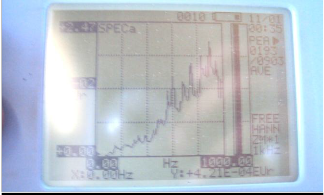
Figure 13: Vibration Spectrum no.9 at Bearing B10 (Time 12:35:57)
5.2.2 Speed Measurement:
With the help of Tachometer, speed measurement is carried out for different loading conditions and for each pass of the billet through the rolls. For carrying out speed measurement, the Tachometer is placed at the center of cross sectional face of rotating shaft.
Firstly, speed measurement is done for Bearing B10. This is carried out for seven passes of billet into rolls. The comprehensive data of speeds for the bearing B10, B9 and B7 is detailed in Table 1.
5.2.3 Time Measurement:
Time measurement is done as per the time data available on FFT Analyzer. The difference in time between two consecutive spectrums is noted down one by one. The detail time measurement is shown in Table 1.
IJSER © 2011 http://www.ijser.org
International Journal of Scientific & Engineering Research, Volume 2, Issue 12, December-2011 6
ISSN 2229-5518
5.2.4 Load Measurement:
Load measurement is done with the help of Fiber Pressuriser. Before starting of rolling mill the tension in a spring of Fiber Pressuriser has been adjusted as per the size of billet, which is used to roll through rolls of rolling mill. This Fiber Pressuriser gives proper reading of a load during operation. Thus for every pass a value of load is estimated as shown in Table 1.
Table 1: Values of RPM & Load for each Pass & Time at
Bearing B10
Time (PM) | 12 :31 :23 | 32:14 | 32:27 | 33:24 | 33:47 | 34:37 | 35:10 | 35:33 | 35:57 |
Pass No. | 7 | 1 | 2 | 3 | 4 | Idle | 5 | 6 | Idle |
RPM | 233 | 230 | 235 | 235 | 225 | 238 | 230 | 235 | 238 |
Load (kg) | 800 | 1100 | 400 | 600 | 1650 | 0 | 1000 | 500 | 0 |
5.2.5 Vibration Amplitude Measurement:
Vibration amplitude measurement is done with the help of Vibration Spectrums. For vibration amplitude measurement, the pertinent frequencies of the components are taken into account, which are placed at the side of bearing on which the spectrum are taken. For each frequency of component the vibration amplitude is measured, which is bearing wise tabulated as shown in Table 2.
Table 2: Values of Amplitudes at different Frequencies at each spectrum for Bearing B10
These Amplitudes are then compared with standard
Vibration Amplitude Limit. These limits are as follows:
a) for Vibration Amplitudes at Bearing Frequencies:
Good 0.00 to 0.20 mm Usable 0.20 to 0.43 mm Still Acceptable 0.43 to 0.65 mm Not Acceptable > 0.65 mm
b) Limits for Vibration Amplitudes at
Gear-Mesh Frequencies:
Good 0.00 to 0.27 mm Usable 0.27 to 0.64 mm Still Acceptable 0.64 to 0.976 mm Not Acceptable > 0.976 mm
6. RESULT & DISCUSSIONS:
This article deals with the discussions about the load variation during rolling process in a rolling mill and its effect on the vibration amplitudes. The load variation also affects the life of rolling mill components.
IJSER © 2011 http://www.ijser.org
International Journal of Scientific & Engineering Research, Volume 2, Issue 12, December-2011 7
ISSN 2229-5518
In present rolling mill, the components which are
near to bearings are failed frequently. To find out the reasons behind the cause, fault diagnosis is essential. Hence fault diagnosis [22] of some components is also discussed.
6.1 Justification for Choosing Gear As An Element for the Validation Of Proposed Theory:
When the billet enters in a roll, a process resistance is offered to the shaft of a roller. This process resistance provides a load torque to the shaft of a roller. The induced load torque is then transferred from the roller shaft to the motor shaft by some power transmitting elements such as a) gears, b) belts, c) couplings. As the load torque increases conversely motor produce additional driving torque to overcome this load torque. The additional induced torque provides further tooth load at the tip of tooth. This action is time variant. Hence, the gear experiences time variant loading conditions. Thus, the gear produces the vibrations. Because of this variant loading condition, the chances of gear tooth failure are more. This is the reason for selection of gear as an element for validation of proposed theory.
6.1.1 Validation with observed value of Amplitude for 1-GMesh frequency of PI1-GE1 for bearing B10:
A phase wise discussion is given below:
Phase (A-B):
In figure 4, point ‘A’ denotes the seventh or final pass of a rolling operation. While, taking the vibration spectrum, the applied load is 800 Kg. The amplitude obtained at this point ‘A’ for 1-GMesh frequency is 0.2 mm.
Now at point ‘B’, the load is 1100 Kg for first pass of billet through rolling mill and the corresponding amplitude is 0.187 mm at 1-GMesh frequency. The phase A-B shows declined pattern of amplitude, hence according to the theory the reaction on Bearing B10 should be increased and corresponding amplitude should also be increased, but graph shows reduction in amplitude from point ‘A’ to point
‘B’.
The probable reasons for this phenomenon are discussed as under:
When the amplitude wants to reach its maximum value, so many mechanisms provide disturbances to it. These disturbances are discussed below:
(a) Sometimes, heavy spot locations and its phase are
not known, which creates additional disturbances, when the phenomenon of proposed theory occurs.
(b) An unanticipated unbalance forces may create additional disturbances, which would setup during phenomenon.
(c) If bearing alignment gets disturbed during the phenomenon, it induces disturbances.
(d) At the side of bearing B10 a coupling C3 is present, which provides additional pulling of shaft S5. This pulling of shaft S5 provides restriction for its corresponding deflection.
Phase (B-C):
At point ‘C’ the load is 400 Kg for second pass and corresponding amplitude is 0.08 mm. The phase B-C shows declined nature of amplitude. Here reaction at Bearing B10 is reduced and there is corresponding drop in amplitude from point ‘B’ to point ‘C’. Hence the proposed theory is valid for this phase.
Phase (C-D):
At point ‘D’, the load is 600 Kg for third pass and corresponding amplitude is 0.2 mm. This phase C-D is incremental one. Here reaction at Bearing B10 is increased in comparison with previous case.Thus there is corresponding increment in amplitude from point ‘C’ to point ‘D’. Hence the proposed theory is also valid for this phase.
Phase (D-E):
At point ‘E’, the load is maximum i.e.1650 Kg for fourth pass and corresponding amplitude is also maximum i.e. 0.322 mm. This phase is also incremental one. Here reaction at Bearing B10 is increased much more as compared to previous case. Therefore, there is corresponding gain in amplitude
from point ‘D’ to point ‘E’. Thus, this phase follows the proposed theory.
Phase (E-F):
At point ‘F’, the load is minimum i.e. Rolling Mill is
running idle and corresponding amplitude is reduced to
0.188 mm. This phase shows declined nature. Here reaction
at Bearing B10 is reduced to very low level as compared to previous case and there is corresponding drop in amplitude
IJSER © 2011 http://www.ijser.org
International Journal of Scientific & Engineering Research, Volume 2, Issue 12, December-2011 8
ISSN 2229-5518
from point ‘E’ to point ‘F’. Hence here also proposed theory
is valid.
Table 3: Time vs Amplitude at different RPM, Load and
Pass Number at 1-GMesh Frequency for Bearing B10
Time (PM) | 12 :31 :23 | 32:14 | 32:27 | 33:24 | 33:47 | 34:37 | 35:10 | 35:33 | 35:57 |
Pass No. | 7 | 1 | 2 | 3 | 4 | Idle | 5 | 6 | Idle |
RPM | 233 | 230 | 235 | 235 | 225 | 238 | 230 | 235 | 238 |
Load (kg) | 800 | 1100 | 400 | 600 | 1650 | 0 | 1000 | 500 | 0 |
Amp (mm) | 0.2 | 0.187 | 0.08 | 0.2 | 0.322 | 0.188 | 0.1 | 0.08 | 0.056 |
Phase (F-G):
The point ‘G’ denotes the fifth pass of a Rolling
operation. When spectrum is taken at bearing B10, the
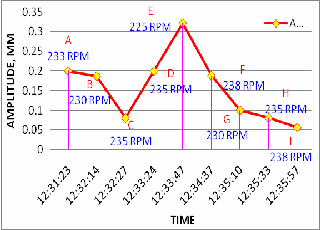
Figure 14: Time Vs Amplitude at 1-GMesh Frequency for
Bearing B10
load at point ‘G’ is 1000 Kg .The amplitude at this point for
1-GMesh frequency is 0.1 mm. Actually according to
proposed theory the amplitude has to be increased, because at point ‘F’ the machine is at no load condition, while the load at ‘G’ is 1000 Kg. But the phase F-G shows declined trend. The reason to this decrease in amplitude is already discussed in the phase A-B.
Phase (G-H):
The point ‘H’ denotes the sixth pass of a Rolling operation. When spectrum is taken, the load is of 500 Kg i.e. half of previous case. The amplitude at this point ‘H’ for 1- GMesh frequency is 0.08 mm. In this case amplitude falls
from point ‘G’ to ‘H’ as the load falls down from 1000 kg to
500 kg. Hence proposed theory is valid for this phase too.
Phase (H-I):
At point ‘I’, the load is minimum i.e. rolling mill is
running idle and corresponding amplitude is reduced to
0.056 mm. This phase also shows declined nature. Here reaction at bearing B10 is reduced further to very low level as compared to previous case and there is corresponding drop in amplitude from point ‘H’ to point ‘I’. This phase also follows proposed theory.
Similar validations can be carried out at different frequencies of the components for the bearing B9 and B7 which are shown in appendix 1.
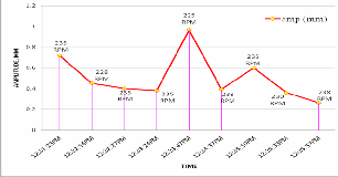
6.2 Fault Diagnosis:
6.2.1 Bearing B10:
Following facts are emerged out from the graph of time vs amplitude for bearing B10
(Kindly refer appendix-I):
The amplitude 0.69 mm at 225 rpm and at
momentarily maximum peak load condition of 1650 kg exceeds the safe vibration limit of 0.65 mm at IR frequency. Hence, inner race problem of bearing B10 is cognized. All the amplitudes corresponding to OR and BS frequency are within safe vibration limits.
Similarly all the amplitudes corresponding to 1- GMesh and 2-GMesh frequencies of gear GE1 are within safe vibration limits, but the amplitude of 0.986 mm at 225 rpm and peak load of 1650 kg at 3-GMesh frequency exceeds safe vibration limit of 0.976 mm, hence gear tooth problem is suspected. But it is felt that the additional induced reaction at this bearing due to increased in load torque may contribute additional amplitude at 3-GMesh frequency.
Similar diagnosis is carried out for remaining bearings.
7. CONCLUSIONS:
From the present investigation, some important conclusions are drawn which are discussed below:
1) Through this work, an alternative approach of
‚vibration based condition monitoring technique‛, for maintenance of a rolling mill is proposed. If one implements this approach then cost of maintenance can be saved by 30 %, as compared
IJSER © 2011 http://www.ijser.org
International Journal of Scientific & Engineering Research, Volume 2, Issue 12, December-2011 9
ISSN 2229-5518
to present cost of maintenance.
2) A new logic is proposed, which states that, ‚As load is increased in the components of rolling mill, conversely the reactions in the bearings increases‛. This increase in reaction of a bearing is then responsible for increase in amplitudes at corresponding frequencies of components.
3) Using the gathered field data a proposed theory is validated. This validation is confirmed for various phases of rolling operation, while for some of the phases the validation is considerable.
4) Through this technique, it is possible to diagnose the internal problems such as inner race, outer race and roller spinning problem of bearings and gear teeth damage problem in earlier stage.
5) Early detection reduces the catastrophic failure of components of rolling mill by using CBM. Hence Condition Monitoring is the best technique for all machines relating to the process plant.
APPENDIX-I GRAPHS OF BEARING B10
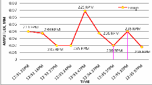
Figure 15: Time Vs Amplitude at IR Frequency for Bearing B10
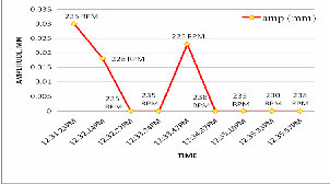
Figure 16: Time Vs Amplitude at OR & BS Freq. for Bearing B10

Figure 17: Time Vs Amplitude at 1-GMesh Freq. for Bearing B10
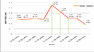
Figure 18: Time Vs Amplitude at 2-GMesh Frequency for Bearing B10
IJSER © 2011 http://www.ijser.org
International Journal of Scientific & Engineering Research, Volume 2, Issue 12, December-2011 10
ISSN 2229-5518
re 19: Time Vs Amplitude at 3-GMesh Frequency for Bearing B10
8. REFERENCES:
[1] Barkov A.V. et.all, ‚Condition Monitoring and Diagnostics of
Rotating machines Using Vibration,‛ VAST, Inc., in 1997.
[2] Biswas R.K., ‚Vibration based condition monitoring of rotating
Figu
2002.
[18] Ray A.G., ‚Monitoring rolling contact bearings under adverse conditions‛, Second International Conference on vibration in Rotating Machinery, P.P.169-174.
[19] Dr. Satyanarayana. M. R. S.,‛Condition Monitoring of Crusher in Coal Handling Plant of Dr NTTPS‛, International Conference on Multi Body Dynamics 2011, Vijaywada, India.P.P.23-132.
[20] Sharma P.C.,‛ Manufacturing Technology‛, S. Chand
Publications, P.P.201-210.
[21] Singh G.R.P., ‚Improving Equipment Availability and Reliability Through Condition Monitoring at Cold Rolling Mill Complex of Tata Steel‛, Tata Search,2000- Maintenance System Design
for Cold Rolling Complex.
[22] Singh B.K., et.all ,‛Condition Monitoring and Machine Fault Diagnosis‛ Indo-US Symposium on Emerging Trends in Vibration and Noise Engineering, 18-20 March 1996,
P.P.321-331.
[23] Technical specification of the FFT Analyser model SA-78 from the operating manual of Rion.
Machines‛, International conference on condition monitoring
(NCCM-2006), December’2006.
[3] Boto P.A., ‚Detection of bearing damage by shock pulse measurement‛, Ball Bearing Journal (S.K.F.) P.167.
[4] Collacot R.A.‛A Handbook of vibration monitoring and diagnosis‛.
[5] Compbell John D. et.all,‛Maintenance Excellence‛, Marcel
Dekker Inc, New York, Publication.
[6] Hicho M.D., ‚Using vibration measurement and Analysis for Predictive Maintenance”, Noise and vibration control worldwide, pp.261-266.
[7] Higgins Lindley R. et.all,‛Maintenance Engineering Hand Book”,
McGraw-Hill Inc New York.
[8] Laparo Kenith A. et. all, ‚Fault Detection and Diagnosis of Rotating Machinery”, IEEE Transaction, Industrial Electronics Vol.47, No.3, Oct 2000,P.P. 1005-1014.
[9] Levitt Joel, ‚Maintenance Management‛, Industrial Press Inc
Publication.
[10] Dr.Mackel I.J., Maintenance and quality related condition monitoring in Rolling mills, presented at the AISE Annual Convention in Chicago.
[11] Mathew J., et.all, Journal of vibration, acoustics, stress and reliability in design by ASME vol.106.
[12] Miao Qiang, et.all, School of Mechatronics Engineering, University of Electronic Science and Technology of China had presented “An on-line fault Classification system with an adaptive model re-estimation algorithm”, 23rd January 2006.
[13] Milne Robat ‚Amethyst: An Expert Systems for the Diagnosis
of Rotating Machinery‛ Proceeding IFToMM, 7th World Conference on Theory of Machines and Mechanisms Madrid Spain, P.P. 287-292, 1987.
[14] Mukhopadhyay C.K.et.all,‚On-Destructive Evaluation Techniques for Condition Monitoring‛, Volume-86, IEEE Journal, September 2005.
[15] Natarajan R. et.all,‛Plant Engineering and Management”
Tata McGraw-Hill Publishing Company Limited New Delhi. [16] Orhan Sadettin et.all,‛ Vibration monitoring for defect diagnosis
of Rolling Element Bearings as a predictive maintenance tool”.
[17] Randal R.B., ‚State of the Art in Monitoring Rotating Machinery”, ISMA 2002, International Conference on Noise and Vibration Engineering, Leuven, Belgium, September
[24] Tervo Jyrk, et.all, ‚Intelligent Techniques for Condition
Monitoring of Rolling Mill”, ESIT 2000, 14-15 September 2000, Aachen, Germany, P.P.330-334
[25] Wadhwani S.et. all,‛Wavelet Based Vibration Moni-toring”,
Volume-85, IEEE Journal, September 2005.
IJSER © 2011 http://www.ijser.org