International Journal of Scientific & Engineering Research, Volume 5, Issue 3, March-2014 941
ISSN 2229-5518
VLSI IMPLEMENTATION OF MULTIPLE ERROR RECOVERY IN TMR SYSTEM USING SCAN-CHAIN
Athira R, V J Arul Karthick
Abstract— Scan chain based multiple error recovery technique for a triple modular redundancy (TMR) system is used to detect and correct multiple errors in TMR systems. This method uses scan chain flip flops to detect and correct faulty modules. The errors are detected at the module’s outputs. This technique can detect both multiple transient faults and latent faults. The transient faults are the temporary faults. These are detected by using the scan chain flip flops. A fault is referred to as latent if it is not propagated to the system outputs but does cause a mismatch between the states of the TMR modules. The latent faults are detected by comparing the internal states of the TMR modules. Upon detection of any mismatch, the faulty modules are located and the state of a fault free module is copied into the faulty modules. In case of detecting a permanent fault, the system is degraded to a master/checker configuration by disregarding the faulty module. This technique uses a voter circuit to detect the faulty module. This is designed and implemented using Xilinx ISE 13.2 and verified using MODELSIM 6.3g.
Index Terms— Triple Modular Redundancy (TMR), roll-forward error recovery, scan chain, Scan chain based error recovery technique for TMR (ScTMR).
1 INTRODUCTION
—————————— ——————————
OWADAYS, the use of embedded systems in safety- critical applications such as avionics, process control,

and patient life support monitoring has become a common trend. Such a system often has both timing constraints and fault tolerance requirements. To meet the reliability require- ment, such embedded systems should be equipped with ap- propriate error detection and correction mechanisms. Howev- er, achieving a high level of reliability and meeting the timing requirements are conflicting objectives, i.e., the reliability en- hancement may have a negative impact on timing constraints. The general idea for achieving error detection and correction is to add some redundancy (i.e., some extra data) to a mes- sage, which receivers can use to check consistency of the de- livered message, and to recover data determined to be cor- rupted.
TMR is a fault tolerant technique. A traditional TMR system consisting of three redundant modules and a voter at the modules outputs. A major shortcoming of the traditional TMR is its inability to cope with TMR failures. TMR failure refers to a failure in a TMR system caused by multiple faulty modules or a faulty voter. In case of independent fault arrivals in two different modules, if none of the faults is overwritten, it may result in a TMR failure.
————————————————
• Athira R is currently pursuing master’s degree program in VLSI Design in SNS College of Technology, Anna University, Coimbatore, India
PH-0099623823835. E-mail: 89athira@gmail.com
• V J Arul Karthick is Assistant Professor in Department of Electronics and Communication Eengineering in SNS College of Technology, Coimbatore, India. E-mail: karthick.arul@gmail.com
For long term applications, the absence of appropriate re- covery mechanisms significantly increases the probability of TMR failure occurrence. To address this issue, TMR should be equipped with a transient error recovery technique. Most of the previous TMR based error recovery techniques proposed so far exploit retry mechanisms. These techniques are not suit- able for tight deadline applications, as the re-computation may result in a task completion after its deadline.
A TMR based technique applicable to general purpose cir- cuits is ScTMR, which provides recovery for both transient and permanent errors in TMR systems. ScTMR significantly reduces the probability of TMR failures, it suffers from two major shortcomings. First, ScTMR cannot recover a single faulty module in the TMR system in the presence of latent faults. A fault is referred to as latent if it is not propagated to the system outputs but does cause a mismatch between the states of the TMR modules. In the presence of a mismatch be- tween the states of the TMR modules, once an error is detected at the output of either of the modules, the system will fail to restore its fault free state. Second, ScTMR is unable to recover the system if multiple faults are simultaneously propagated to the outputs of two modules.
The Scan chain based Multiple Error Recovery TMR has the ability to locate and remove latent faults in TMR modules as well as to recover the system from multiple faults affecting two TMR modules. Compare the internal states of TMR mod- ules to locate and restore the correct state of faulty modules using the state of non-faulty modules. In case of permanent faults, the faulty module is disregarded and the system is de- graded to a master/checker (M/C) configuration. As compared to other TMR based recovery techniques, this technique has negligible area overhead, as it reuses the available resources
IJSER © 2014 http://www.ijser.org
International Journal of Scientific & Engineering Research, Volume 5, Issue 3, March-2014 942
ISSN 2229-5518
within the circuit.
2 OVERVIEW OF TMR
Triple Modular Redundancy (TMR) is the fault tolerant tech- nique. A traditional TMR system consists of three redundant modules and a voter at the module’s outputs. TMR is a fault tolerant form of N-modular redundancy, in which three sys- tems perform a process and that result is processed by a ma- jority-voting system to produce a single output. If any one of the three systems fails, the other two systems can correct and mask the fault.
To explain triple-modular redundancy, it is first necessary to explain the concept of triple redundancy as originally in- troduced by Von Neumann. The concept is illustrated in Fig 1. TMR is a well-known fault tolerant technique for avoiding errors in integrated circuits. The TMR scheme uses three iden- tical logic blocks performing the same task in random with corresponding outputs being compared through majority vot- ers. The majority voters perform a very important task in the TMR approach, because they are able to block the effects
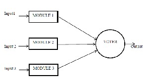
Fig 1: TMR system
the voters can be placed in the end of the combinational and sequential logic blocks, creating barriers for the upset effects. The problem is to determine the optimal partition of the TMR logic that must be voted inside the circuit in order to reduce the probability that upsets in the routing affect two distinct redundant parts that are voted by the same voters. A small size block partition requires a large number of majority voters that may be too costly in terms of area and performance. On the other hand, placing only voters at the last output increases the probability of an upset in the routing affecting two distinct redundant logic parts overcoming the TMR.
2.1 Voter Circuit
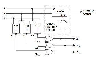
In a TMR system, detection and correction of a faulty module is a challenging issue. In particular, a wrong detection or ina- bility to locate the faulty module can significantly affect the system reliability. To address this issue, we have presented a voter that can identify the faulty module. Additionally, the proposed voter can also detect possible faults occurring in the comparators. The proposed voter can be used in both ScTMR and SMERTMR techniques.
Fig 2: Voter circuit
The architecture of the proposed voter is depicted in Fig 2. As shown in the figure, three comparators (C12 , C13 , and C23 ) are used to represent any mismatch between TMR modules. As an example, TE23 signal is activated once a mismatch be- tween Outputs II and III is detected. If one of the modules generates an erroneous output (e.g., Output I), two of the comparators (here, C12 and C13 ) will activate the mismatch signals (here, TE12 and TE13 ) and only one of the comparators (here, C23 ) will not activate the corresponding mismatch signal (here, TE23 ). In case of a faulty comparator (e.g., C13 ), only the corresponding signal (here, TE13 ) is activated and the other signals (here, TE12 and TE23 ) are deactivated. This voter can also detect and recover from permanent faults. In order to de- tect permanent faults, the proposed voter employs three input signals (named Pr12 , Pr31 , and Pr23 ), which are derived by the ScTMR controller. In the normal state and during transient error recovery process, these three signals are deactivated (Pr12
= Pr13 = Pr23 = 0) and as a result, the values of E12 , E13 , and E23
become equal to TE12 , TE13 and TE23 , respectively. Upon detec- tion of a permanent fault, (Pr12 , Pr13 , and TE23 will be activated by the ScTMR controller.
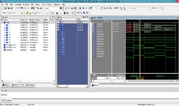
Fig 3: Output of the voter circuit
Fig 3 shows the output of the voter circuit. Here the module 3 is the faulty module. For this corresponding error signal E13 and E23 are activated.
IJSER © 2014 http://www.ijser.org
International Journal of Scientific & Engineering Research, Volume 5, Issue 3, March-2014 943
ISSN 2229-5518
3 EXISTING SYSTEM
3.1 Architecture of SMERTMR
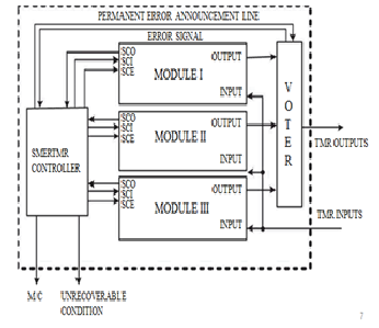
Fig 4: SMERTMR block diagram
The fig 4 shows the block diagram of SMERTMR. In the SMERTMR technique, the comparison mode is activated in two cases: 1) when an error is detected by the voter and
2)when the checkpoint signal is activated. In the latter case, the checkpoint signal is employed to intentionally trigger the comparison mode in order to eliminate latent faults.
When an error is detected by the voter, it indicates the
SMERTMR controller by an error signal. The SMERTMR de- termines the error type and triggers appropriate recovery mechanism to eliminate this error.
The SMERTMR controller is activated in two modes. Ie, comparison mode and recovery mode. In the comparison mode, the module’s outputs are compared and the faulty module is detected. In the recovery mode the module is recov- ered from the fault.
6.1 SMERTMR State Diagram
The fig 5 shows the state diagram of SMERTMR. Initiallythe system is in the normal state. Upon the detection of an error by the voter, it enters in to the comparison mode. If no error is found, then it resets. If the error is single or multiple transient fault, then it enters into the recovery mode. If the transient error is recovered successfully, it resets to normal mode. Otherwise, it enters nto the unrecoverable condition. The system will halts here. If the fault is permanent, then the system is degraded into the master/checker configurartion disregarding the state of the TMR modules. Either of the master or checker module is faulty, then the system enters into the unrecoverable condition. When the error is detected by the voter and the comparison process cannot detect faulty
modules, then the system enters into the unrecoverable condition
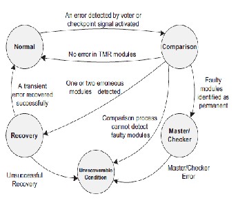
Fig 5: SMERTMR state diagram
.
3.3 Comparison Process
In the SMERTMR technique, whenever the voter detects an error, it activates an error signal to alert the SMERTMR con- troller. Upon activation of the error signal, the SMERTMR con- troller switches from the normal operation to the comparison mode to locate the faulty modules. After locating the faulty modules, SMERTMR switches to the recovery mode to recover the faulty modules using the state of one of the fault-free modules.
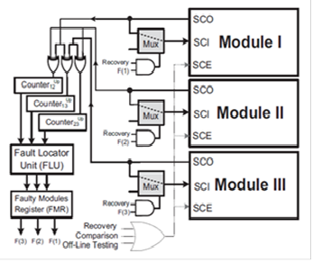
Fig 6: SMERTMR in comparison mode
Fig 6 shows a simplified block diagram of the SMERTMR
IJSER © 2014 http://www.ijser.org
International Journal of Scientific & Engineering Research, Volume 5, Issue 3, March-2014 944
ISSN 2229-5518
controller circuit working in the comparison mode. In this mode, the internal states of all TMR modules are shifted out using the scan chains and all module pairs (I/II, I/III, and II/III) are
compared. As shown in Fig 6, there are three counters, namely, counter12 , counter13 , and counter23 , to store the number of mis- matches between each module pairs. For example, counter12 stores the number of mismatches between modules I and II. To this end, the SMERTMR controller enables scan chains of the SMERTMR modules and configures the multiplexers in such a way that the SCO signal in each module is connected to the SCI signal of the same module. During the shift operation, the internal states of the modules are compared using XOR gates. Whenever a mismatch is detected, the corresponding counter is incremented by one unit. Using this configuration, counterij will contain the number of mismatches between modules i and j after Lsc clock cycles. The Fault Locator Unit (FLU) detects the faulty module using the faulty module detection algorithm. The FLU stores the
faulty module number in the Faulty Modules Register (FMR).
Algorithm 1: Faulty Modules Detection Algorithm
1: if Ci j = Cik = Cjk = 0 then
2: next_state ← Normal mode
3: else if i, j, k: (Cij = Cik ) & (Cjk = 0) then
4: next_state ← Recovery mode
5: FMR ←i
6: else if i, j, k : (Cjk = x) & (Cik = y) & (Cij = x + y) then
7: next_state ← Recovery
8: FMR ← i, j
9: else
10: next_state ←Unrecoverable condition
11: end if
The following will show how an SMERTMR system can de-
tect and locate faulty modules by comparing the internal states of the system modules. Suppose that there is an SMERTMR system including three modules named i , j, and k. The system may be in the following four situations.
1) All modules are fault-free: In this case, all three counters will be
equal to zero.
2) There is only one faulty module: Let us assume that module i is faulty and it contains x erroneous flip flops and the other mod- ules, i.e., modules j and k are fault free. In this case, we will have counter ij = counter ik = x. Note that, since both modules j and k are fault-free, counter jk will be equal to zero (i.e., counter jk = 0). After extracting the number of mismatches, the system enters the recovery mode and the state of module i is recovered using the state of either modules j or k.
3) There are two faulty modules: Suppose that there are two
faulty modules (e.g., modules i and j ) and one fault-free module (here, module k). Then counterik = x, counter jk = y, and counteri j = x + y.
4) All modules are faulty: In this case, SMERTMR is not able to locate the faulty modules and it enters the unrecoverable condi- tion.
Fig 7: Output of the SMERTMR in comparison mode
Fig 7 shows the output of the SMERTMR in comparison mode. In this the modules outputs are compared and the faulty module is detected. The faulty module number is stored in the Fault Module Register (FMR).
3.4 SMERTMR in Recovery Mode
After the identification of fault-free and faulty modules by the FLU unit at the end of the comparison process, the system enters the recovery mode if there is one or two faulty modules in the system. Otherwise, it returns to the normal mode. In the recovery mode, the state of the faulty module is recovered by the state of fault-free modules using the employed scan chains.
Fig 8: SMERTMR in recovery mode
Fig 8 shows a simplified block diagram of the SMERTMR controller circuit in the recovery mode. In this mode, the SMERTMR controller enables the scan chains of the SMERTMR modules and configures the multiplexers as fol- lows: The SCI signal of fault-free modules is connected to the
IJSER © 2014 http://www.ijser.org
International Journal of Scientific & Engineering Research, Volume 5, Issue 3, March-2014 945
ISSN 2229-5518
SCO signal of the same module. In addition, the SCI signal of the faulty module is connected to the SCO of one of the fault- free modules. As shown in Fig 8, the value of the
FMR register is used in the recovery mode to select the in-
coming driver of the appropriate signal driver for the SCI sig- nals. Using the configuration shown in Fig 8, the state of one of the fault-free modules is copied into the faulty modules after Lsc clock cycles.
While shifting out the states of the modules in the recovery
mode, similar to the comparison mode, they are also com- pared to find any mismatch due to faults occurring in the re- covery process. During the recovery process, whenever a mismatch is detected and the corresponding counter value containing the number of mismatches is decreased by one unit. At the end of the recovery process, all counters should be zero. This is because, for each mismatch, the corresponding
counter is incremented by one unit during the comparison
process and is decremented by one unit during the recovery process. If either of the counters is nonzero at the end of the recovery process, it is indicative of another fault occurrence during the recovery process. In this case, the SMERTMR sys- tem would enter the unrecoverable condition since such faults cannot be located.
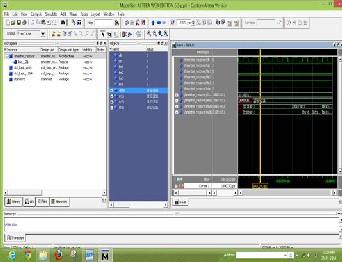
Fig 9: Output of the SMERTMR in recovery mode
The fig 9 shows the output waveform of SMERTMR in recov- ery mode. In this the error is recovered using scan chain cir- cuitry. The state of the fault free module is copied into the faulty module using this scan chain circuitry.
4 PROPOSED SYSTEM
In the proposed system, the comparison mode and recovery mode of SMERTMR embedded in a single unit. The error de- tection and recovery is carried out in a single unit.
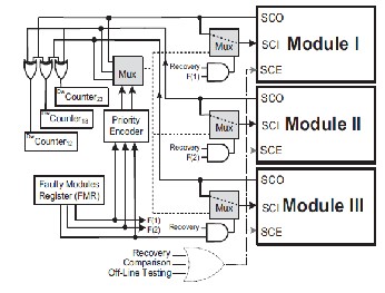
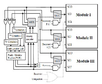
Fig 10: Multiple error recovery in TMR using scan-chain
In the proposed system, we can detect and recover fault in a single unit. That means we can combine the comparison mode and recovery mode of the SMERTMR. The architecture of the proposed system is shown in Fig 10. In this proposed system, the internal states of all TMR modules are shifted out using the scan chains and all module pairs (I/II, I/III, and II/III) are compared. As shown in Fig 10, there are three counters, name- ly, counter12 , counter13 , and counter23 , to store the number of mismatches between each module pairs. The SCO signal in each module is connected to the SCI signal of the same mod- ule. During the shift operation, the internal states of the mod- ules are compared using XOR gates. Whenever a mismatch is detected, the corresponding counter is incremented by one unit. Using this configuration, counteri j will contain the num- ber of mismatches between modules i and j after Lsc clock cy- cles. After the identification of fault-free and faulty modules by the FLU unit at the end of the comparison process, the sys- tem enters the recovery mode if there is one or two faulty modules in the system. Otherwise, it returns to the normal mode. While shifting out the states of the modules, they are also compared to find any mismatch due to faults occurring in the recovery process. At the end of the recovery process, all counters should be zero. This is because, for each mismatch, the corresponding counter is incremented by one unit during the comparison process and is decremented by one unit dur- ing the recovery process. If either of the counters is nonzero at the end of the recovery process, it is indicative of another fault occurrence during the recovery process.
Fig 11 shows the output of the proposed system. Which identifies the faulty module and the state of the fault free module is copied into the faulty module using the scan chain circuitry. Thus finally the faulty module became fault free.
IJSER © 2014 http://www.ijser.org
International Journal of Scientific & Engineering Research, Volume 5, Issue 3, March-2014 946
ISSN 2229-5518
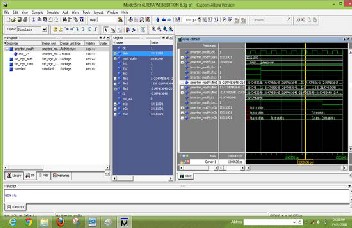
Fig 11: Output of the proposed system
4 CONCLUSION
In this paper, we presented a roll-forward technique, multiple error recover in TMR system using scan-chain, to recover multiple errors in TMR systems. In this first designed a voter circuit. Then designed an SMERTMR in comparison mode and SMERTMR in recovery mode. Then combine these two modes in a single unit. This technique detects, locates, and corrects multiple faults affecting single and two faulty modules. The results also show that the area and the performance overheads are less.
ACKNOWLEDGMENT
The authors would like to thank a great support of Anna Uni- versity and SNS Group of Institutions to complete this project successfully.
REFERENCES
[1] M. Ebrahimi, S. G. Miremadi, H. Asadi, and M. Fazeli, “Low-Cost Scan-Chain-Based Technique to Recover Multiple Errors in TMR Sys- tems,” IEEE Trans. Very Large Scale Integr. (VLSI) Syst., vol. 21, no. 8, pp. 1454–1468, Aug. 2013.
[2] M. Ebrahimi, S. G. Miremadi, and H. Asadi, “ScTMR: A scan chain based error recovery technique for TMR systems in safety-critical ap- plications,” in Proc. Design Autom. Test Eur. Conf. Exhibit., 2011, pp. 1–4.
[3] L. Wang, N. Touba, Z. Jiang, S. Wu, J. L. Huang, and J. C.-M. Li, “CSER: BISER-based concurrent soft-error resilience,” in Proc. 28th IEEE VLSI Test Symp., Apr. 2010, pp. 153–158.
[4] X. She and K. S. McElvain, “Time multiplexed triple modular redun- dancy for single event upset mitigation,” IEEE Trans. Nucl. Sci., vol.
56, no. 4, pp. 2443–2448, Aug. 2009.
[5] P. K. Samudrala, J. Ramos, and S. Katkoori, “Selective triple modu- lar redundancy (STMR) based single-event upset (SEU) tolerant synthesis for FPGAs,” IEEE Trans. Nucl. Sci., vol. 51, no. 5, pp. 2957–
2969, Oct. 2004.
[6] S. Yu and E. J. McCluskey, “On-line testing and recovery in TMR
systems for real-time applications,” in Proc. Int. Test Conf, 2001, pp.
240–249.
[7] G. Rui, C. Wei, L. Fang, D. Kui, and W. Zhiying, “Modified triple
modular redundancy structure based on asynchronous circuit tech- nique,” in Proc. 38th Int. Symp. Defect Fault Tolerance VLSI Syst.,
2006, pp. 184–196.
[8] G. Rui, C. Wei, L. Fang, D. Kui, and W. Zhiying, “Modified triple modular redundancy structure based on asynchronous circuit tech- nique,” in Proc. 38th Int. Symp. Defect Fault Tolerance VLSI Syst.,
2006, pp. 184–196.
[9] J. Yoon and H. Kim, “Time-redundant recovery policy of TMR fail- ures using rollback and roll-forward methods,” IEE Proc. -Comput. Digit. Tech., vol. 147, no. 2, pp. 124–132, Mar. 2000.
[10] S. D’Angelo, C. Metra, and G. Sechi, “Transient and permanent fault
diagnosis for FPGA-based TMR systems,” in Proc. Int. Symp. Defect Fault Tolerance VLSI Syst., 1999, pp. 330–338 [7] K. G. Shin and H. Kim, “A time redundancy approach to TMR failures using fault-state likelihoods,” IEEE Trans. Comput., vol. 43, no. 10, pp. 1151–1162, Oct.
1994.
IJSER © 2014 http://www.ijser.org