International Journal of Scientific & Engineering Research, Volume 4, Issue 9, September-2013 234
ISSN 2229-5518
Using NFC and modified CS Algorithm based
unified power flow conditioner for compensating power quality problem
M.Vishnu vardhan1 , Dr. P. Sangameswararaju2
Abstract— At the present time, the power quality (PQ) related issues are more absorbed in power electronic devices. For compensating PQ disturbances the different types of power devices are used. Unified power quality conditioner (UPQC) is one of the power electronics devices that are used for enhancing the PQ. To reduce the PQ disturbances, the performances of UPQC must be improved. In this paper, neuro fuzzy controller (NFC) with modified cuckoo search (CS) algorithm is proposed for improving the performance of UPQC, so as to reduce the power quality problem. Here, the error and change of error voltage of the system is applied to the neural network. The output of the neural network is optimized by the proposed algorithm. Using the output of proposed algorithm, the optimized fuzzy rule is generated and the discharging capacitor voltage is calculated from the bias voltage generator. The proposed technique is implemented in MATLAB working platform. The performance of the proposed method is evaluated and compared with the NN, NFC, FLC, ANFIS and ABC methods.
Index Terms— UPQC, Power quality disturbance, fuzzy logic controller, neural network, modified cuckoo search algorithm
—————————— ——————————
lectric PQ has become the concern of utilities, end users, manufacturers and all other customers [6] due to the de- regulation approach. PQ problem is recognized as current or frequency of power system that results in the stop working or disoperation of customer device, any deviations in voltage [2] [3] [4] [8]. PQ problem mostly demonstrates due to the ac- commodation of power electronic loads such as rectifier, ad- justable speed drives, programmable logic controllers, com- puters, printers, faxes, fluorescent lighting and most other office tools etc. which will cause the decline of voltage and current waveforms [5]. Most significant PQ problems are volt- age sags, micro-interruptions, long interruptions, voltage spikes, voltage swells, voltage fluctuations, harmonic distor- tion etc. The sternest PQ problem is the Voltage sag that allo- cates 70% of all PQ problems [7]. Modern electronic apparatus and tools, such as microprocessors, microcontrollers, tele- communications equipment and responsive computerized equipments etc. are responsible to PQ problems. Hence, we need avoiding PQ problem as much as possible. In manu- script, to avoid PQ problem, there are combinations of Custom Power Devices (CPDs) such as Distribution Static compensator (DSTATCOM), the Dynamic voltage restorer (DVR), uninter- ruptible power supply (UPS), Solid State Transfer Switch
(SSTS), UPQC etc. are explained [18].
For the development of power quality due to its fast reaction, high reliability and nominal cost, UPQC is a competent CPD [16] [17]. In power allocation plans, it can be used to improve the current and voltage-related PQ problems at the same time [11]. UPQC employs two inverters that are combined to a common DC link with an energy storage capacitor. The main components of UPQC are force and series inverters, DC capac-
itors, low pass & high pass filters and series transformer [12]. Series inverter is used to balance voltage related disturbance, by introducing opposite voltage in the line where shunt in- verter is used to compensate current associated disturbance by providing opposite current that conclude the disturbance [9] [10] [13]. Low and high pass filter help in the reduction of harmonics in the system voltages and currents [14]. DC capaci- tor maintains the both inverters for competent and fast opera- tion during turmoil. Yet, it has the disadvantage of high re- leasing time due to which it needs the assist of an appropriate controller for managing its voltage.
A NF controller is a control system based on the neural net- works (NN) and fuzzy inference systems (FIS). NN is the arti- ficial copy of human brain and doesn’t need any mathematical model for its structural set of relations. FIS is realistic rules based copy is stimulated based on fuzzy rules and NN is toiled based on instruction dataset. The neural network train- ing dataset are generated from the fuzzy rules. NN is relevant in real life functions like regression analysis, classification, data processing, robotics etc. In actual applications like indus- trial control, human decision making, image processing etc, Fuzzy logic is relevant. ABC optimization algorithm is a rela- tively new member of swarm intelligence. ABC efforts to copy usual performance of true honey bees [19] in food foraging. At first the ABC algorithm was enhanced for nonstop function optimization problems; yet it can moreover be efficiently ap- plied to dissimilar other optimization problems [20]. The CS is a population based optimization algorithm and related to sev- eral others meta-heuristic algorithms start with an arbitrary first population which is obtained as host nests or eggs [40]. CS is used to improve voltage profile, which is the main crite-
IJSER © 2013 http://www.ijser.org
International Journal of Scientific & Engineering Research, Volume 4, Issue 9, September-2013 235
ISSN 2229-5518
rion for power quality enhancement and mitigate power losses of the distribution network [21]. It is relevant in valid world functions like power systems, management, image classifica- tion etc. This paper is structured as follows: Section 3 describes about the problem formulation and proposed methodology. Previously, recent related research works are explained in Sec- tion 2. The simulation results are discussed in Section 4. Final- ly, the conclusion section is presented in the section 5.
An strategy based on cuckoo search (CS) which was used for optimal distributed generation (DG) allocation to enhance voltage profile and diminish power loss of the distribution network has been offered by Zahra Moravej et al. [21]. The voltage profile was the major criterion for power quality de- velopment. It was designated by two indices: voltage devia- tions from the target value which must be diminished and voltage variations from the initial network devoid of DG which must be exploited. The CS has been balanced with other evolutionary algorithms such as genetic algorithm (GA) and particle swarm optimization (PSO) and dissimilar cases have been examined for indicating the applicability of their sug- gested algorithm. Their results designate the improved presentation of CS compared with other techniques. In their suggested method, the meeting rate was not responsive to the parameters applied, so the fine alteration was not required for any specified problems.
UPQC Yash Pal et al. have proposed a control strategy for a three-phase four-wire for an enhancement of different PQ problems [22]. The UPQC was accomplished by the integra- tion of series and shunt dynamic power filters (APFs) and both APFs share a common DC bus capacitor. To obtain the reference signals for series APF, a unit vector template tech- nique (UTT) based control method has been used while the ICosΦ theory has been utilized for the control of Shunt APF. Under a dissimilar mixture of linear and non-linear loads, in terms of power-factor correction, load balancing, source neu- tral current mitigation, voltage and current harmonics mitiga- tion, mitigation of voltage sag and swell, and voltage dips in a three-phase four-wire distribution system, the appearance of the implemented control algorithm has been evaluated. Their simulation results have been accomplished by means of the MATLAB/Simulink, and it confirms that the proposed control system could sustain the functionality of the UPQC.
The shunt active filter (SHAF) was proposed by [S]. Mikkili et al. [23] which was used to get the power quality of the electri- cal network was better developed in this proposal by justify- ing the harmonics with the help of Types 1 and 2 fuzzy logic controllers (Types 1 and 2 FLC) using dissimilar fuzzy mem- bership functions (MFs). DC-link voltage constant must be maintained to generate the compensating reference currents in this projected technique. Various were considered and the performance of their proposed control strategy has been eval- uated for those source conditions in terms of harmonic mitiga- tion and DC-link voltage regulation. The practicability of the
proposed control strategy was sustained by the presentation of complete real-time results using real-time digital simulator.
K. Manimala et al. [24] have described the automatic classifica- tion of power quality incidents by means of Wavelet Packet Transform (WPT) and Support Vector Machines (SVM). The features of the interruption signals were eliminated by WPT and set to the SVM for competent classification. The two opti- mization techniques were used to their proposed classification system, such as, genetic algorithm and replicated annealing. In a fully automatic mode, their proposed scheme was recog- nized the top discriminative features and evaluated the top SVM kernel parameters. The competence of their proposed detection technique was compared with the conventional pa- rameter optimization techniques like grid search method, neu- ral classifiers like Probabilistic Neural Network (PNN), fuzzy k-nearest neighbor classifier (FkNN). They have proved that their proposed method was reliable and produces for all time better results.
A design of adaptive neuro-fuzzy inference system (ANFIS) for the turbine speed control for purpose of improving the power quality of the power production system of a split shaft microturbine has been presented by Yuksel Oguz et al. [25]. To improve the function presentation of the microturbine power generation system (MTPGS) and to reach the electrical output magnitudes in required quality and value (terminal voltage, operation frequency, power drawn by consumer and produc- tion power), a controller depended on adaptive neuro-fuzzy inference system was designed. It was observed from the re- production results that with the microturbine speed control prepared with ANFIS, when the MTPGS was stimulated un- der dissimilar loading conditions, the terminal voltage and frequency values of the system can be determined in required operation values in a very little time exclusive of significant fluctuation and electrical production power in preferred quali- ty can be accomplished.
Currently, PQ associated issues are of most concerned because of their significance in power operating tools. Nonlinear loads for instance, adjustable speed drives (ASD), programmable logic controllers (PLC), energy-efficient lighting and rectifiers, led to PQ problems. General PQ problems are voltage sag, voltage spike, voltage swell, harmonic distortion, voltage fluc- tuations, voltage unbalance and interruptions. If the system sustains the PQ, it will supply constant operation or in addi- tion it offers unsteady operation. As a result preserving of PQ is an important one in power operating tool. From the associ- ated research works, it illustrates that intellectual methods are implemented in different electrical and electronics applica- tions. In the earlier papers, intellectual methods are being ap- plied for developing the PQ problem compensating perfor- mance of UPQC. This method develops the presentation of UPQC in PQ problem compensation by optimizing the output of the NN which offers the PQ disturbance in terms of voltage to the bias voltage generator. Bias voltage generator is the sub-
IJSER © 2013 http://www.ijser.org
International Journal of Scientific & Engineering Research, Volume 4, Issue 9, September-2013 236
ISSN 2229-5518
stitution for DC link capacitor which performs as a DC voltage source for two dynamic power filters of UPQC. DC link capac- itor has the difficulty of widespread discharging time owing to which full compensation of the voltage disturbances is not feasible or getting impediment. To evade these matters, bias voltage generator is applied in the place of DC capacitor. For improved compensation of PQ problem, Bias voltage genera- tor adjusts the DC link voltage quick and efficiently. Bias volt- age generator has two inputs: reference voltage and calculated voltage from NF controller. The ABC algorithm is very profi- cient for multimodal and multidimensional fundamental func- tions. However, the convergence rate of the algorithm is re- duced when functioning with constrained problems, compo- site functions and numerous non discrete functions. Therefore, the presentation of NFC with the UPQC is influenced. In this paper, NFC with modified CS algorithm is proposed, which is an enhancement over the existing controllers for developing the compensating performance of the UPQC.
3.1. Need for Advancement in Proposed approach
CS algorithm) method based UPQC
frequency component and to reduce the high frequency com-
ponent of specific voltage signal. Then, the output of low pass
filter is applied to voltage injection transformer. Hence, the
obtained output from injection transformer maintains PQ in
the operating system. Injected voltage in phase by injection
transformer is expresses as
As of now, various research works have been tried in the sec- tion of PQ maintenance and enhancement. Some devices such![]()
V = 2 V 2 − V 2
inj s1 s 2
(1)
as DVR, UPS and many others are used for maintaining the quality power supply. But, these devices are capable of main-
mVdc
![]()
inj
(2)
taining only the symmetrical or unsymmetrical power sup- plies, so the PQ is not maintained at all time. To avoid these problems, an enhanced NF controller [29] has been proposed. But, the system developed by [29] had drawbacks like they can only be applied to small networks. Hence, to overcome the issue involved in previous methods, we have proposed a NFC
2 2 Where,Vinj is the injected voltage in the phase,
Vs1 is the pre voltage variation, Vs 2 is the post voltage varia-
tion, m is the modulation index andVdc is the normal rated DC
voltage respectively. The output voltage and current of single
phase system can be expressed as follows,
(3)
with modified CS optimization algorithm. In this paper, pro-
posed method is used for regulating the DC link voltage and
Voutput
= A ⋅ sin(ωt + θ )
(4)
reducing the harmonics of the inverter. The NFC has com- bined neural network and fuzzy logic controller. Here, NFC is
I output = I s ⋅ cos ωt. cosθ
Where, A is the amplitude of out-
used to improve the voltage regulation and reduce the com- plexity. Then the error and change of error voltages are ap- plied to the input of the neural network. The output of the neural network can be regulated by DC link voltage. The out- put performance of the neural network is optimized by using the proposed (modified CS) algorithm. Then the determined dc link voltage is applied to the regulation system of UPQC and the PQ problem is compensated.
3.2. Proposed (NFC- modified CS) method based UPQC Enhanced NFC based UPQC controller for PQ maintenance in
a single phase load connection which is illustrated in Fig.1. It consists of bias voltage generator which connects both Series Active Filter (SAF) and Shunt Active Filter (SHAF). Here, the
inVputs to the bias voltage genVerator are Reference Voltage
( ref ) and calculated Voltage ( cal ) which is calculated from
NF controller bLased on proposed algorithm. A Synchronous
Link Inductor ( SL ) is connected in series with SHAF to gen-
erate a voltage with respect to the PQ disturbance and a low
pass filter is connected in series with SAF to pass low fre
put voltage, ω is the angular frequency andθis the phase angle
of output voltage at t=0. Using Equation 3 and 4 the sinusoidal output voltage and current are calculated. The PQ of the sup- ply mainly depends on the output voltage of the system. Hence, in the paper the PQ of the system output voltage is
maintained only during the time of system operation. Here, the voltage discharge capacitor of conventional UPQC is re- placed by the bias voltage generator.
3.2.1. Utilization of FLC and NN using Bias voltage generator in proposed method
In this section, the bias voltage generator is used for eliminat- ing the high discharging time of the DC link capacitor. The proposed optimization algorithm optimizes the output of the calculated voltage from NN controller so that the output of NF controller is able to inject the compensating voltage in the sin- gle phase line. Inputs to the NF controller are error voltage and change in error voltage of the device and are determined as shown below,
E(k ) = Vdc (ref )− Vdc
Figure 1: General structure of the proposed (NFC- modified
∆E = E(k ) − E(k −1)
(5)
(6)
IJSER © 2013 http://www.ijser.org
International Journal of Scientific & Engineering Research, Volume 4, Issue 9, September-2013 237
ISSN 2229-5518
Where,
E(k −1)
is the previous state error. The error voltage
and change of error voltage are calculated by using the above formula and the values are applied to the inputs of NF con- troller. FLC is an important part in the research of PQ en- hancement and it contains three parts, such as fuzzification, fuzzy rules and defuzzification. Here, the input is error &
change in error voltage (i.e.,
E(k ) & ∆E ) and output is calcu-
lated voltage (V f ) set are changed into a fuzzy sets. Then, the
fuzzy rules are produced. It is known as fuzzy inference sys-
tem (FIS). After a decision made, output which is in fuzzy set
form is converted back to crisp set by defuzzification. This is the last phase of the FLC. Output of the FLC ( V f ) is generat- ed by using centroid defuzzification method. Here, the lin-
Figure 2: NN structure for proposed method.
3.3. Enhancement of NN output using proposed Algorithm
Step 1 Objective function
In this section, objective function is considered as an optimiza- tion problem. Here, the optimization problem is defined as follows,
guistic variables of inputs and output are Negative Big, Nega-
min(EV ) = V
ref
− V NN
NcNal
(7)
tive Medium, Negative Small, Zero, Positive Small, Positive
Where, Vref
and Vcal
are denoted as the reference Voltage of
Medium, Positive Big and it is referred as NB, NM, NS, ZE,
the bias voltage generator and calculateNdN voltage from NN. It
PS, PM, PB in the rules base. The developfed fuzzy rules are
V
had to be minimized by varying the cal
in the search space
V
tabulated in TABLE I. Using fuzzy rules, cal is determined.
Table I: Fuzzy rules for determining V f
of its limits, so that the DC link voltage regulation performs well and quickly by bias voltage generator and thus improv- ing the compensation performance of UPQC. This is achieved
by optimizing output of the NF controller, i.e., V NN . Then NF
controller output (V NN
gorithm.
Step 2 Initialization
cal
) is given as an input of proposed al-
In this section, the host nests are randomly initiated. Here, nest is an array of size ‘n’.
xa = {x1 , x2 ,..........xn }
(8)
Here,
xa denotes
NN the and each nest xa is a solution
vector to the opti-
Vcal
mization problem. It can hold n
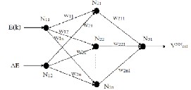
3.2.2Training process of neural network (NN)
NN is the artificial intelligence technique for estimating the
output based on its training and doesn’t need any mathemati-
cal model for its structure. It has played a major role in the maintenance of PQ. The proposed feed forward NN diagram is illustrated in the Fig.2. It is used to determine the calculated
number of variables, which are optimized so as to minimize the objective function.
Step 3 Creation of new cuckoo
A cuckoo randomly generates new solutions by using expo-
nential function and determines the quality of solutions. The
exponential function is represented as follows,
voltage for bias voltage generator. It consists of three layers,
xt +1
wi
such as input layer, hidden layer and output layer. In this pa-![]()
=
b 1 + exp(levy ∗ w )
per, the back propagation NN training and weight adjustment w
i +1
(9)
are used. The training process of the back propagation is rep-
resented. The training process of the Eba(kck) propagation is rep-
Where i is the weighting function of the neural network and the range of the weight is [0, 1] i.e., wi ∈ (0,1) . The levy func-
tion is specified as the range between -230V to 230V. The
resented. Here, initialize the inputs
& N∆NE and weights
V
of the network. Then the network output ( cal
) is calculated
cuckoo is evaluated using the objective function to determine
BP
and also, BP error ( error ) is determined. The BP error is de-
fined as subtracting the network output from target output. For finding the ∆w , adjust the weight ( w = w + ∆w ) of each
neuron in the network. Repeat the above process until BP er-
ror gets minimized to a least value i.e., 10. BPerror < 1 .
the quality of the solutions. The exponential function is calcu- lated for each iteration.
Step 4 Fitness function
Here, the fitness function ( F ) of all the nests are evaluated by using the following formula,
The working process of neural network has given here. The
fitness
function (F ) = min(EV )
(10)
NN
cal
NN is trained using back propagation in order to pro- vide values for any error values. Here, the calculated
From the above condition, the quality of the solutions is
measured. A nest is selected among n randomly, if the quali-
voltage is optimized with modified CS algorithm to improve NN’s performance in order that, effective compensation per- formance of the UPQC is achieved. Optimization done by modified CS algorithm is explained as below.
ty of new solution in the selected nest is better than the old
solutions, it is replaced by the new solution (cuckoo). Other-
wise, keep the previous solution as a best solution.
IJSER © 2013 http://www.ijser.org
International Journal of Scientific & Engineering Research, Volume 4, Issue 9, September-2013 238
ISSN 2229-5518
START
NN
Initialize ( Vcal )
randomly
Using the above equation, the compensating performance of UPQC is improved. The DC link voltage of the UPQC is var- ied based on the load variation. Here, DC voltage regulation is achieved by using the output of NF controller based modified cuckoo search algorithm via bias voltage generator. The input of the bias voltage generator is Vref and the calculated voltage V cal ., which is obtained from NF controller based on modified cuckoo search algorithm. Bias voltage generator is used to dis-
Generate a cuckoo ( xb )
randomly by exponential function
Evaluate the fitness func- tion ( fit )
if ( fit xa > fit xb )
Yes
Replace with the ( fit xb ) as a new solution
Discard worst nest based on the probability pa and new nest ones built using equation (2)
Save the present best
(optimal) solutions
No If max iteration
is met
No
Keep the previous solutions
charge the inverter diodes quickly. The harmonics of inverter output voltage is eliminated by the low pass filter, and then the low pass filter output is applied to injection transformer. The output of injection transformer is the delivered and en- hanced voltage of the system. The detailed analysis is de- scribed in the following section.
In this section, the proposed (NFC-Modified CS) method is
implemented in MATLAB platform. Here, the error and
change of error voltage of the system is applied to the neural
network. The output of the neural network is optimized by the
proposed algorithm. Using the output of proposed algorithm,
the optimized fuzzy rules are generated and the discharging
capacitor voltages are calculated from the bias voltage genera-
tor. The proposed method is used to improve the performance of UPQC for compensating the power quality problems. The performance of the proposed controller is tested with power quality problem. The performance of the proposed controller
is analyzed, which is based on the reference voltage and line voltages. The analyzed outputs of the proposed method are compared with neuro fuzzy controller (NFC), neural network (NN), fuzzy logic controller (FLC), ANFIS and ABC methods. The proposed method based unified power flow conditioner simulated diagram is illustrated below.
4.1. Evaluation of Performance analysis and metrics
Here, the implementation parameters are represented, which is specified as their values and that are described as follows:
Yes
DC Voltage (Vdc )
Reference Voltage (V )
: ± 230V
: ± 230V
Error Voltage
(e(n))
: - 230V to +230V
END
Change of error voltage (∆e)
: - 230V to +230V
Step 5 Discard worst nest
In this part, the worst nests are discarded based on their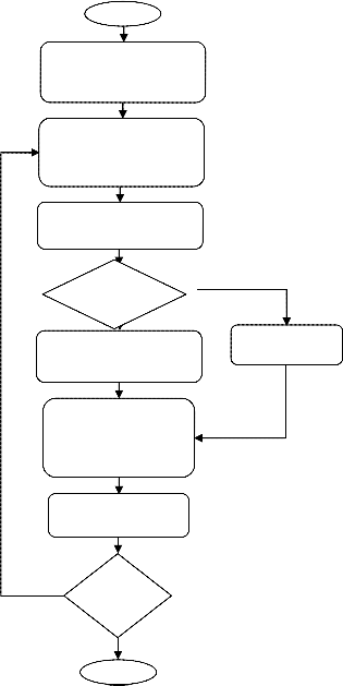
In different time instants, the reference voltage and line volt-
age with PQ problem are determined. The PQ affected line volt-
age can be improved using the proposed controller and the exist-
probability pa
values and new ones are built using the equa-
ing technique controller. Then the proposed method performanc-
tion (2). After that, rank the best solutions based on their quali-
ty. Then identify the present best solutions as optimal solu-
tions.
Step 6 Stopping Criterian
This process is repeated until the terminatNioNn iteration
es are compared with NFC, NN, FLC, ANFIS and ABC methods. Then evaluate the better results from the comparison analysis. Here, the reference voltage and line voltage with PQ problems are illustrated in Fig. 4 and 5. Then the line voltage with PQ prob-
V
reached. Here, the best solution is optimized cal
. From the
lems are defined at the time instant T= 0.17, 0.05, 0.19, 0.11, 0.04
output of hybridization techniques (FLC & ANN), we can evaluate the values with the help of mean operation. The fol- lowing formula is used for calculating theV cal .
f NN
sec and clearing time of the PQ problem is calculated. The en-
hanced PQ line voltages are evaluated using the proposed meth-
od and illustrated in the Fig. 5(a). Similarly, the enhanced PQ line
voltages are evaluated in the NN, FLC, NFC, ANFIS and ABC
Vcal
![]()
= vcal + vcal
2
(11)
techniques.
IJSER © 2013 http://www.ijser.org
International Journal of Scientific & Engineering Research, Volume 4, Issue 9, September-2013 239
ISSN 2229-5518
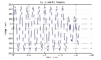
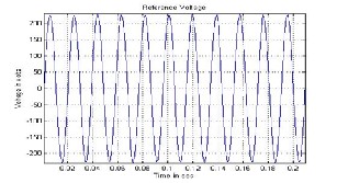
Figure 4: Reference Voltage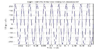
Figure 5: Line voltage with PQ problem at T=0.17 sec
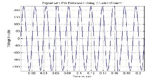
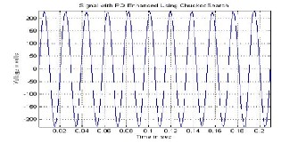
Figure 7: The line voltage with enhanced
PQ problem at T=0.19 sec in proposed method
From the above performances, the existing techniques
took more time to solve the PQ problem when compared to
the other method. Here, the proposed and existing technique
processes are noted and it shows that the proposed controller
is used for solving the PQ problems in an efficient time man-
ner.
In the time instant T= 0.19 sec, the PQ problems are occurring in proposed method, NN, FLC, NFC, ANFIS and ABC methods. The clearing time of these methods are 0.2, 0.21, 0.21, 0.21, 0.21 and 0.21 (all values in seconds) respectively. In the proposed method, the clearing PQ problem duration is 0.1 seconds. From the time instant, the PQ problems are highly cleared with the use of proposed method when compared to other techniques. Then the PQ problems are occurring in NN, NFC, FLC, ANFIS and ABC at 0.05 seconds then clearing at 0.07, 0.07,0.07,0.07 and 0.07 seconds respectively. In the proposed controller, the PQ problems are occurring at 0.05 seconds and clearing at 0.062 seconds so that the total PQ problem duration is 0.012 seconds. Moreover for all the time instants, the performances of the proposed method are evaluated. Similarly, the clearing time of the PQ problems in NN, NFC, FLC, ANFIS and ABC methods is measured with all the different time instant (T=0.17, 0.11, 0.04 seconds) and their per- formances are evaluated. Then performance of the proposed method is compared with the other methods.
The RMS voltage of the proposed and existing meth- od is calculated from the above illustrations and tabulated in table II. Moreover, the RMS voltages of the existing methods get decreased compared to the proposed method, when the PQ problem occurred. Then the Root Mean Square (RMS) voltage (Vrms ) of enhanced voltage is calculated as follows:
(12)![]()
V = v p rms
Where, 2 Vp is the peak voltage value. The
RMS voltage value is used to estimate the PQ enhancement of
the operating system.
Table II: RMS voltages of proposed method, ABC-NFC, ANFIS, ANN, FLC and NFC
IJSER © 2013 http://www.ijser.org
International Journal of Scientific & Engineering Research, Volume 4, Issue 9, September-2013 240
ISSN 2229-5518
4.1.1. Performance analysis using FFT
By using FFT analysis, the voltage magnitude of the proposed
method and their waveforms are evaluated. Here, the input
voltage and frequency is denoted as 230V and 50Hz respec-
tively. The power quality disturbance signal is specified as the
error signal. This power quality problem causes amplitude
errors in the FFT analysis. From the above illustrations, the
voltage signal is disturbed in the power quality problem at the
different time (T=0.07 and 0.01 seconds) instants. When the PQ
problem occurred, the RMS voltage is highly increased. After
that, the PQ affected line voltage (RMS) variation is measured,
which is specified at the range from 70 to 150 Hz. From the frequency 70 and 80 Hz, the RMS voltage magnitude is slight- ly varied and their variation values are measured. The varia- tion of the voltage magnitude is 80V. Then compensating PQ
problem, the voltage magnitude is highly reduced i.e., 570V. Now the RMS voltage magnitude is 230 V. After that, the line voltage is affected with PQ problem in the time instant (T=0.01 sec) is measured, then the RMS voltage is reduced. Hence, the proposed method highly reduces the PQ problem and their performances are illustrated in Fig. 8 (a).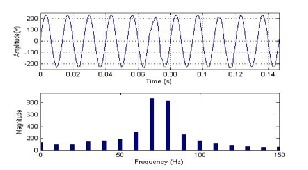
Figure 8(a): FFT analysis of compensating power quality at modi- fied cuckoo search
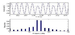
Figure 8(b): FFT analysis of compensating power quality at ABC
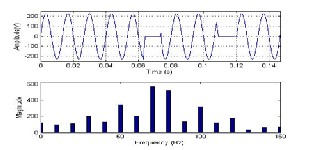
Figure 8(c): FFT analysis of compensating power quality at ANFIS
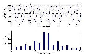
Figure 8(d): FFT analysis of compensating power quality at NFC
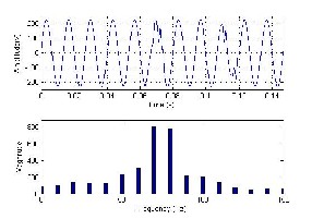
Figure 8(e): FFT analysis of compensating power quality at Fuzzy
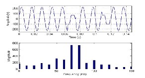
Figure 8(f): FFT analysis of compensating power quality at Neural Network Similarly, the FFT analysis is used to evaluate the performance of the ABC, ANFIS, NN, FLC and NFC method. From the analysis, the voltage signal is disturbed in the power quality problem at the different time (T=0.07 and 0.01 seconds) in- stants. When the PQ problem occurred, the RMS voltage is highly varied i.e., increased. After that, the PQ affected line voltage (RMS) variation, which is measured in the ABC, AN- FIS, NN, FLC and NFC methods that is specified at the range from 70 to 150 Hz. From the frequency 70 and 80 Hz, the RMS voltage magnitude is slightly varied and their variation values are measured. The variation of the voltage magnitude is 20, 20,
10, 60 and 80 (all values in p.u) respectively. Then by compen- sating PQ problem, the voltage magnitude is highly varied or reduced i.e., 570, 630, 560, 360 and 440 (all values in p.u) re- spectively. Now the RMS voltage magnitude is 230 V. After that, the line voltage is affected with PQ problem in the time instant (T=0.01 sec) which is measured and then the RMS volt-
IJSER © 2013 http://www.ijser.org
International Journal of Scientific & Engineering Research, Volume 4, Issue 9, September-2013 241
ISSN 2229-5518
age is reduced. The performance analysis of the existing methods is illustrated in the Fig. 8 (b, c, d, e and f). Therefore, the proposed method highly reduces their PQ problems, when compared to other methods and their performances are evalu- ated.
4.1.2. Performance deviation
The performance deviation is based on the RMS voltage of the
proposed method and other methods. The proposed technique
is analyzed with the performance deviation of ABC, ANFIS,
NFC, FLC and ANN controller. The performance deviation
between the proposed method and ABC controller can be cal-
culated with the following formula,
proposed method ABC
rms rms
problem. The proposed controller was implemented in the MATLAB platform. The voltage sag PQ problems were con- sidered for analyzing the performance of the proposed con- troller. In the proposed controller, the line voltage with the PQ problems occurred in the various time instants and evaluated their clearing time instants of the enhanced PQ problems. Then the FFT analysis is used in the proposed method, ABC, ANFIS, NN, FLC and NFC methods. Similarly, the occurring and clearing time of the PQ problems are measured with the ABC, ANFIS, NN, FLC and NFC methods and the outputs are compared. The proposed controller compensated the PQ prob- lem in less time, when compared to the existing methods. Al- so, the PQ problem occurrences are defined with the different
Deviation (%) =
proposed method rms
time instants (T=0.05, 0.19, 0.11, 0.04, 0.17 sec) the performance
Similarly, the per- formance deviation can also be
calculated between proposed method and ANFIS, FLC, NFC
and ANN for different instances of occurrence of PQ issues
and that are chosen for implementing the proposed controller
and are tabulated in TABLE III.
Table III: Performance deviation of proposed method with ABC, ANFIS, ANN, FLC and NFC
Time (in sec) | Performance Deviation of Proposed Method | ||||
Time (in sec) | ABC | ANFIS | NN | FLC | NFC |
0.05 | 23.91 | 28.26 | 41.30 | 36.95 | 39.13 |
0.19 | 2.27 | 13.63 | 18.18 | 20.45 | 15.90 |
0.11 | 56.81 | 28.18 | 27.27 | 29.54 | 27.27 |
0.04 | 2.27 | 45.45 | 65.90 | 84.09 | 84.09 |
0.17 | 4.54 | 47.72 | 27.27 | 29.54 | 29.54 |
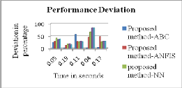
Figure 9: Performance deviation of proposed method with ABC, AN- FIS, NN, FLC and NFC
In the proposed controller, the performance deviation are cal- culated and represented in Fig. 10. It can be deviated positive- ly at a rate of 23.91% rather than ABC, 28.26% rather than ANFIS, 41.30% rather than NN, 36.96% rather than FLC and
39.13% rather than NF controller at T=0.05sec. Then at the time instant (T=0.19 sec), the proposed controller deviates at a rate of 2.27% rather than ABC, 13.64% rather than ANFIS
18.18% rather than NN, 20.45% rather than FLC and 15.91% rather than NFC. Similarly, the performance deviation of the proposed technique achieves a positive rate in solving the de- fined time (T=0.11, 0.04, 0.17 sec) instants. It can be shown that, the proposed controller can achieve a better performance of PQ issues compared with the ABC, ANFIS, FLC, NFC and ANN.
In this paper, the proposed (NFC-Modified CS) method based
UPQC controller was proposed for compensating the PQ
deviations were evaluated in the proposed controller with the
ABC, ANFIS, NFC, NN and FLC techniques. The proposed
technique achieves a positive rate in solving all the defined
instants of occurrences of PQ issues. The comparative results
showed that the proposed controller can achieve a better per-
formance of PQ issues compared with the ABC, ANFIS, NN,
FLC and NFC based controllers.
[1] Ramin Rajabioun, “Cuckoo optimization Algorithm”, Journal of Applied Soft
Computing, Vol.11, pp. 5508–5518, 2011.
[2] B. Kumara Swamy, P. Pavan Kumar and Ch V K R M V Prasad, “A MATLAB Based Power Quality Analyzer (PQA) For Enhancing Power Qual- ity in The System”, International Journal Of Electrical And Electronics Engi- neering Research, Vol.3, No.1, pp.73-86, 2013.
[3] T. Devaraju, V. C. Veera Reddy and M. Vijaya Kumar, “Role of custom power devices in Power Quality Enhancement: A Review”, International Journal of Engineering Science and Technology, Vol.2, No.8, pp.3628-3634, 2010.
[4] S. Khalid and Bharti Dwivedi, “Power Quality: An Important Aspect”, Inter-
national Journal of Engineering Science and Technology, Vol.2, No.11, pp.6485-6490, 2010.
[5] C. Nalini Kiran, “Power Quality Improvement Using Active and Passive Power Filters”, International Journal of Modern Engineering Research, Vol.2, No.1, pp.76-79, 2012.
[6] S. H. Laskar and Mohibullah, “Power Quality Issues and Need of Intelligent PQ Monitoring in the Smart Grid Environment”, International Journal of Emerging Technology and Advanced Engineering, Vol.2, No.9, pp.63-69,
2012.
[7] Nagendrababu Vasa, G. Sreekanth, Narender Reddy Narra and A. Srujana, “Series Compensation Technique for Voltage Sag Mitigation”, International organization of Scientific Research Journal of Engineering, Vol.2, No.8, pp.14-
24, 2012.
[8] Mahesh A Patel, Ankit R Patel, Dhaval R Vyas and Ketul M Patel, “Use of PWM Techniques for Power Quality Improvement”, International Journal of Recent Trends in Engineering, Vol.1, No.4, pp.99-102, 2009.
[9] Paduchuri Chandra Babu and Subhransu Sekhar Dash, “Design of Unified Power Quality Conditioner (UPQC) Connected To Three Phase Four Wire System”, International Journal of Computer and Electrical Engineering, Vol.4, No.1, pp.60-64, 2012.
[10] Saleha Tabassum and B. Mouli Chandra, “Power Quality improvement by UPQC using ANN Controller”, International Journal of Engineering Research and Applications, Vol.2, No.4, pp.2019-2024, 2012.
[11] Laxman Rao and Hari Krishna, “Enhancement of Power Quality by UPQC
IJSER © 2013 http://www.ijser.org
International Journal of Scientific & Engineering Research, Volume 4, Issue 9, September-2013 242
ISSN 2229-5518
Device in SCIG Wind Fram to Weak Grid Connection”, International Journal of Modern Engineering Research, Vol.2, No.5, pp4030-4033, 2012.
[12] Yash Pal, A. Swarup and Bhim Singh, “3P-3W UPQC with zig-zag trans- former for 3P-4W Distribution System”, International Journal on Electrical Engineering and Informatics, Vol.4, No.2, pp.231-244, 2012.
[13] G. Sridhar Reddy, “Feasibility Analysis of DGSC-UPQC”, International Jour- nal of Research and Reviews in Applied Sciences, Vol.4, No.1, pp.32-47, 2010.
[14] Seema P Diwan, H P Inamdar and A P Vaidya, “Simulation Studies of Shunt Passive Harmonic Filters: Six Pulse Rectifier Load-Power Factor Improve- ment and Harmonic Control”, International Journal on Electrical and Power Engineering, Vol.2, No.1, pp.1-6, 2011.
[15] Abdesslem Layeb, “A novel quantum inspired cuckoo search for Knapsack problems”, International Journal of Bio-Inspired Computation, Vol. 3, No.5, pp. 297-305, 2011.
[16] G. Laxminarayana and G. Umesh Kumar, “Power Quality Improvement Using UPQC for Wind Farm Generation System”, International Journal of Advanced Research in Electrical, Electronics and Instrumentation Engineer- ing, Vol.1, No.6, pp.523-530, 2012.
[17] Yash Pal, A. Swarup and Bhim Singh, “Star-Hexagon Transformer Supported UPQC”, International Journal of Electrical and Electronics Engineering, Vol.5, No.1, pp.63-68, 2011.
[18] K. Sandhya, A. Jayalaxmi and M. P. Soni, “Design of Unified Power Quality Conditioner (UPQC) for Power Quality Improvement in Distribution Sys- tem”, International organization of Scientific Research Journal of Electrical and Electronics Engineering, Vol.4, No.2, pp.52-57, 2013.
[19] Nadezda Stanarevic, “Hybridizing artificial bee colony (ABC) algorithm with differential evolution for large scale optimization problems”, International Journal of Mathematics and Computers in Simulation, Vol.6, No.1, pp.194-
202, 2012.
[20] Milan Tuba, Nebojsa Bacanin and Nadezda Stanarevic, “Adjusted artificial bee colony (ABC) algorithm for engineering problems”, WSEAS Transactions on Computers, Vol.11, No.4, pp.111-120, 2012.
[21] Zahra Moravej and Amir Akhlaghi, “A novel approach based on cuckoo search for DG allocation in distribution network”, International Journal of Electrical Power and Energy Systems, Vol.44, No.1, pp.672–679, January, 2013.
[22] Yash Pal, A. Swarup and Bhim Singh, “A control strategy based on UTT and I CosΦ theory of three-phase, fourwire UPQC for power quality improve- ment”, International Journal of Engineering, Science and Technology, Vol.3, No.1, pp.30-40, 2011.
[23] S. Mikkili and A. K. Panda, “Types-1 and -2 fuzzy logic controllers-based shunt active filter Id-Iq control strategy with different fuzzy membership functions for power quality improvement using RTDS hardware”, Interna- tional Journal of power electronics, Vol.6, No.4, April, 2013.
[24] K. Manimala, K. Selvi andR. Ahila, "Optimization techniques for improving power quality data mining using wavelet packet based support vector ma- chine", International Journal of Neuro computing, Vol.77, No.1, pp.36-47,
2012.
[25] Yuksel Oguz, Seydi Vakkas Ustun, Ismail Yabanova, Mehmet Yumurtaci and
Irfan Guney, “Adaptive neuro-fuzzy inference system to improve the power
quality of a split shaft microturbine power generation system”, International
Journal of Power Source, Vol.197, pp.196-209, 2012.
[26] Khairul Najmy Abdul Rani, Mohd Fareq Abd Malek and Neoh Siew-Chin, “Nature-inspired Cuckoo Search Algorithm for Side Lobe Suppression in a Symmetric Linear Antenna Array”, Journal of Radio engineering, Vol.21, No.3, pp.865-874, 2012.
[27] M. Karthikeyan and K. Venkatalakshmi, “Energy Conscious Clustering of Wireless Sensor Network Using PSO incorporated Cuckoo Search”, In pro- ceedings of third IEEE conference on computing communication & network- ing technologies, Coimbatore, pp.1-7, 2012.
————————————————
• Dr.P.Sangameswararaju is currently professor and HOD in EEE dept ,in
SVUniversity, Tirupati,INDIA, Raju_ps_2000@gmail.com
IJSER © 2013 http://www.ijser.org