
= (N2 ÷ N1 )3 (3)
International Journal of Scientific & Engineering Research, Volume 6, Issue 2, February-2015 92
ISSN 2229-5518
Use of the VFD to minimize the throttling effect of the Hostel water supply system by the
automation of the system
1Sanjay N. Huse, 2Ravindra D. Kale, 3Dr. D.R.Mane 4Prof. V.P.Dhote
—————————— ——————————
The hostels buildings are located within campus in the distributed manner. The water supply system from the well to the hostel buildings is operated by the water supply employee. From underground tanks of the buildings to the terrace tank, it is operated by the staff manually. Therefore many times there is mismanagement within the employees and results in the overflow of the water or shortage of the water unnecessarily.
Variable frequency Drives (VFDs) operate by rectifying the incoming AC power to a DC signal and then retransmitting the power signal to the motor at varying frequencies and voltages. VFDs can operate motors with the speeds ranging from nearly 0 to as high as 1.5 times the rated speed.VFD controls the speed of an AC induction motor by controlling the voltage and frequency. The reduction of the supply frequency results in reduction of the impedance of electric circuit.
.
1Dr.B.A.M.University, Aurangabad. (M.S.) India.
2Dr.B.A.M.University, Aurangabad. (M.S.) India.
3Dr.B.A.M.University, Aurangabad. (M.S.) India.
4Govt. College of Engineering, Aurangabad. (M.S.) India.
Therefore, higher current is drawn by the motor and it results in a higher flux and saturation of the magnetic field. Therefore, to keep the magnetic field within working limit, both the supply voltage and the frequency are changed in a constant ratio (fig.1).
Applications of VFD for the pumping stations, controlling of the pump speed by maintaining a specified pressure. The another advantages of the use of VFDs includes less wear on the motor due to reduced speed and torque, soft starting of the motor and gradual accelerations.
Generally the VFDs used most commonly are with the pulse- width-modulation. In centrifugal applications with no static lift, system power requirements vary with the cube of the pump speed. Small reduction in speed or flow can significantly reduce energy use. In addition to energy savings, VFDs offer precise speed control and a soft-starting capability. Soft-starting reduces thermal and mechanical stresses on windings, couplings, and belts. Operating motors at reduced speeds results in other benefit, as well, such as lower bearing loads, reduced shaft deflection, and lower maintenance costs.
IJSER © 2015 http://www.ijser.org
International Journal of Scientific & Engineering Research, Volume 6, Issue 2, February-2015 93
ISSN 2229-5518
= (N2 ÷ N1 )3 (3)
We can use the affinity laws to predict the performance of a centrifugal pump with little or no static head at any speed, if we know the pump’s performance at its normal operating point.
Where,
Q = fluid flow, in gallons per minute (gpm)
N = pump rotational speed, in revolutions per minute (rpm)
H = head, in feet or meters
P = Power in horsepower (hp)
Q1, H1, P 1, N1 = pump performance at normal (initial) operating point
Q2, H2 , P 2, N2 = pump performance at final operating point
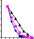
An affinity laws show that the pump head decreases significantly
when the pump speed is reduced to match system flow requirements (see figure 2). Pump shaft horsepower requirements vary as the product of head and flow or as the cube of the pump’s speed ratio.
For the hostel buildings of the Dr. B.A.M. University Aurangabad, presently the water for the daily use purpose is supplied from the farm well with pumping at two stations i.e. at farm wells.
Among the hostels there are underground tanks for collection and storage of the water. From these tanks the water is lifted to the terrace tanks through 3Hp pump motors.
Each hostel is provided with the two groups of four tanks i.e. eight tanks of capacity 2000 liters each and two tanks for the backup storage of the solar water heaters. In this way there are 10 tanks (20000 liters) on each building terrace.
Each group of tanks above the terrace is supplied by the 2” pipelines with at least 24 fittings i.e. elbows, tees, bends, etc. The static head for the some hostel building is about 12 meter and that for other hostels is about 9 meters. The dynamic heads are about
10 meter and 12 meters for two storied buildings. The dynamic heads for the water supply line of three storied hostels about 29 meters.
Fig. 2 The curves showing variation of the Power, Head and
Discharge Vs Speed.
Affinity law equations are as follows,
(Q2÷ Q1 ) = (N2 ÷ N1 ) (1) (H2÷ H1 ) = (N2 ÷ N1 )2 (2)
(P2 / P 1) = (H2 Q2 ) ÷ (H1 Q1 )
Fig. 3 System Head Vs Flow Curve
IJSER © 2015 http://www.ijser.org
International Journal of Scientific & Engineering Research, Volume 6, Issue 2, February-2015 94
ISSN 2229-5518

From the above figure 4, it is clear that there are about 6 no. of ball cocks and the 6 no. of valves for each building. The three valves of a group of the tanks located on the either side of the hostel terrace are throttled to adjust the water flow in the three tanks as shown in fig.4. The throttling of the valve causes unnecessary increase in the head of the pumps and results in the more power consumption and also lengthens the running time period for the pump motor. Also when either tank fills up then the ball cock will shut off the water flow which also increases the pump head and power consumption. Many tanks are too old and broken near the and downside of the pipe inlets which causes wastage of water flow as these breaks are below the pipe level , the ball cocks cannot shut off the inlet flow. Also, many times the solar water heater back up storage tanks does not get filled and therefore the hot water for the bathrooms does not flow. This may be the major drawback of the existing system, as the natural energy source of water heating cannot be used only due to the inefficient water supply.
Fig.6.
Fig. 4Throttling effect on system Head
Overview of the problem- The above stated problem has following issues to solve.
i)To avoid the excess power consumption due to the valve throttling.
ii)To ensure the reliable water supply to the solar back up
storage tanks.
iii)To avoid the overflow and wastage flow of water.
iv) To save the energy by minimizing the friction loss of the system and optimum use of gravity for water transportation.
To solve the all of the above issues it will be feasible to apply the VFD for pump motor speed control and to apply the automation for the water supply system.
consumption due to the valve throttling. The VFD can achieve
this by varying the speed of the motor through frequency and voltage variations.
Also from the equations of the pumps i.e. equations 1 and 3,
It is clear that if the water flow is reduced by 20% by reducing the speed of the pump motor with the help of VFD by
20% will result in the power saving of the approximately 48.8%. (Q1/Q 2)= (N1 /N2 )
(Q1/0.8Q1 ) = (N1/0.8N2 )
and
(P1 /P 2)= (N1 /N2 )3
So, P 2= P1 x (N 2 /N1 )3
= P1 x(0.8N1/N 1 )3
= P1 x (0.8)3
So, P 2= (0.512) P1.
i.e. about 48.8 % power will be saved by the reduction of the flow rate by only 20%. This will require to run the pump motor by the
20% more duration to fill up the tanks i.e. instead of 3 hours operation it will take an half hour extra to lift the required quantity of the water.
A) For the student hostel with three storied buildings, the 3
HP motor is operating for more than 3 hours per day.
Therefore at present,
per day Energy consumption is about 7 units.
Per annum energy electricity consumption = 6.7x30x12=2412 units.
Per annum electricity billing cost @ Rs.7.79/- =Rs. 19630.8/- After installation of the VFD,
per day Energy consumption is about 3.5 units.
Per annum energy electricity consumption = 3.5x30x12=1260 units.
Per annum electricity billing cost @ Rs.7.79/- =Rs. 9815.4/- Per annum electricity savings = 2520-1260= 1152Units.
Per month cost savings = (201-105) x 7.79 = Rs. 747.84/- Per annum cost savings = 1152 x 7.79 = Rs. 8974.08/-
Simple payback period = 20000÷ 747.84 =26.74 = 27 months. For two hostels with three storied buildings,
Per annum electricity savings = 1152 x 2=2304Units.
IJSER © 2015 http://www.ijser.org
International Journal of Scientific & Engineering Research, Volume 6, Issue 2, February-2015 95
ISSN 2229-5518
Per month cost savings = 747.84 x 2 = Rs. 1495.68/-
Per annum cost savings = 8974.08x 2= Rs. 17948/-
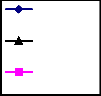
Yes
Start
Manual No
Operation?
B) For the two storied Hostel, 3 HP motor is operating for more than an hours per day
Yes
No
Is water in No
UG tank?
Max Water level?
Yes
Therefore at present,
per day Energy consumption is about 4 units.
Per annum energy electricity consumption = 4x30x12=1440 units. Per annum electricity billing cost @ Rs.7.79/- =Rs. 11217.6/- After installation of the VFD,
Enable Pump Motor ON
Yes No
Is Water level ≥ Default?
Disable Motor
Disable Motor and Give alarm LED
End
per day Energy consumption is about 2.04 units.
Per annum energy electricity consumption = 2.04x30x12=734.4 units.
Per annum electricity billing cost @ Rs.7.79/- =Rs. 5727.97/- Per annum electricity savings = 1440-734.4= 705.6Units.
Per month cost savings = (120-61.2) x 7.79 = Rs. 458/- Per annum cost savings = 705.6 x 7.79 = Rs. 5496.6/- Simple payback period = 20000÷ 458 = 44 months
For four hostels with two storied buildings,
Per annum electricity savings = 705.6 x 4=2822.4Units.
Fig.5 Auto control flow chart
The level sensors as a part of the water level monitors will detect the water levels within tanks. The solenoid valves can be operated with the water level controllers to shut off the pipe inlet of the tanks.
Also there is lot of water wastage and on the other hand there is
also deficiency of water frequently.
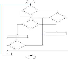
Instead of the above existing system, if the new pipe
line work within all hostels with one extra tank on the student hostel no. 3 is installed and connection is done as shown in the fig.7.
Per month cost savings = 458 x 4 = Rs. 1832/- Per annum cost savings = 5497x 4= Rs. 21988/-
Inlet pipe from
pump
Water tank Pipe
Solenoid valve
Solar backup storage water tank
Water tank
Fig.6. proposed water supply pipeline connection pattern
In the proposed system, the extra water tank is to be installed over the hostel with highest terrace height, as this is the building with
IJSER © 2015 http://www.ijser.org
International Journal of Scientific & Engineering Research, Volume 6, Issue 2, February-2015 96
ISSN 2229-5518
three floors and greater height (MSL) than other buildings and
also there is the underground tank available.
The water from UG tank to newly proposed tank to be
lifted by the pump motor operated with VFD control.
From this tank, the solar back up water storage tanks of other
hostels to be connected by 4” HDPE pipe i.e. the water from the proposed tank to the solar back up tanks will flow by gravity action. Also from the solar back up tank to other solar back up tank to be connected in parallel by the 2” pipeline and all other eight tanks (two groups of four tanks) to be connected by the 4” pipeline.
The purpose of the using HDPE pipe is that it does not require any fitting like tee, elbow etc and therefore sharp bend of the line is avoided which will reduces the friction losses.
In this system the dynamic head or friction loss will be
compensated by the gravity action for the distribution purpose and the required height of the tank is only to overcome the friction losses compensated by the gravity.
Also the length of the supply pipeline for this proposed system is
within 300 meters only for each hostel.
One unit saved is equal to two units generated. The average
annual energy conservation after the use of the VFD is about
5126.4 units. The carbon dioxide emission rate for electricity
generation is approximately 0.9 Kg/ kWh. Therefore the annual saving in the green house gas(GHG) emission is about 4613.76
Kg. The amount of saving in the GHG gas emission is small but it will have little participation in the share of India’s carbon reduction responsibility.
Also there will be reliable water supply for the hostel buildings with the manpower saving. The auto control will stop the overflow and the wastage flows of the water which will results in the water conservation. The TOD operation of the motor will benefit to the both University and also MSEDCL i.e. utility company.
Future scope: After the implementation of these, the real time monitoring is possible which will report the interruption to the concerned employee to avoid the long shut down times.
Also as the total head of the system is reduced, the pump can be operated with the solar power generation with PV module.
1. Guidebook for National Certification Examination for Energy Managers and Energy Auditors, Bureau of Energy Efficiency, Oct 2010.
2. Principles of Pumps and Pumping Installation, Institution of Railway Electrical Engineers (IREE), April 2010.
3. S.P. Raghuvanshi et al. / Energy Conversion and
Management 47 (2006) 427–441.
4.
IJSER © 2015 http://www.ijser.org