International Journal of Scientific & Engineering Research, Volume 4, Issue 12, December-2013 293
ISSN 2229-5518
Unconventional Modeling and Stress Analysis of
Femur Bone under Different Boundary Condition
Muhammad Shahzad Masood, Atique Ahmad, Rizwan Alim Mufti
Mechanical Engineering Department, Pakistan Insitute of Engineering and Applied Sciences Islamabad (PIEAS), Pakistan Abstract— Biomechanics deals with the application of mechanics laws to living organism. Conventionally CAD models of complex biological shapes are prepared through Medical imaging software while in this paper an unconventional approach is employed for modeling of complicated geometry of human femur bone to make realistic investigations. Two orthogonal views are employed for modeling of complex femur bone with the help of 3D animated open source software Blender 2.63a. Pro/ENGINEER translated Blender prepared polygonal model into CAD model that is imported to ANSYS for analysis under different boundary condition. Results of stress analysis for heterogeneous bone structure vary with individuals that are beneficial for orthopedic surgeons.
Keywords— ANSYS; Biomechanics; Finite element analysis; Femur bone
—————————— ——————————
1 INTRODUCTION
iomechanics involves the application of mechanical prin- cipals to biological objects. It is not so simple to apply me- chanical laws to biological objects. Artificial objects are simples in shape and they can be easily modeled whereas bio- logical objects posses complex shape which are difficult to
sentation is a cumbersome task. Their complexity poses a great challenge in modeling. It is extremely difficult to prepare bone model using conventional CAD software. In this paper, Com- plex shaped femur bone model was prepared by employing an open source 3D animated software Blender 2.63a. Blender
IJSER
prepare CAD model. Nonlinear and anisotropic natures of
biological objects are the source of difficulties in meshing and
analysis [1].
Importance of computer simulations can’t be denied in the
field of biomechanics. Advanced processing power of com-
puters has made it easy to simulate the biological objects pos-
sessing complexity in shape, nonlinearity and anisotropy in
properties. Finite element method is the best way for linear,
nonlinear and couple field analysis of biological objects. Tradi-
tionally MRI, CT scan and advanced imaging techniques were
employed to prepare model for simulation purposes which is
costly [2].
Femur bone is essential part of human body which pro-
vides support to human body while standing, sitting and
walking. Cortical, compact tissues and other small parts is
main constituent of Femur bone. Femur bone is complex in
shape and it has different composition. The thickness of femur
bone is in between 4-8mm and length is between 260-293mm
[3]. Research has been carried out on femur bone fracture us-
ing mathematical modeling and different software. Somkid et
al. performed modeling using CT scan and analysis was made
using FEMLEB software [4]. Daan Waanders et al. studied
fatigue creep damage at cement bone interface using finite
element. T. San Antonio et al. focused on orientation of ortho- tropic materials properties in finite element model [5].
This study presents a new way of modeling the complex biological objects. Femur bone polygonal model was prepared with the help of Blender 2.63a. Reverse engineering feature of Pro/Engineer was beneficial for conversion of polygonal model into CAD model. This CAD model was imported to ANSYS 10 for analysis under different loading conditions.
2 FEMUR BONE MODELING
Due to the complex shape of bones their geometrical repre-
makes a polygonal model by approximating the surface of
model with the polygons. Polygonal model is in the form of
polygons mesh.
Extrusion modeling was adopted to make polygonal model
of femur bone with the help of orthogonal views (front and
side view). In extrusion modeling contours of object make 2D
shape with help of one view. Then using 2nd view at some
angle, a 3D shape is created. Femur bone model was prepared
with quad face polygons and completed by scaling, rotating
and extruding to collate the model with images.
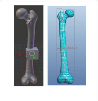
Figure 1 Blender Model (Left) and Pro/ENGINEER Model (Right)
Blender prepared model consist of polygonal surfaces and
CAD model possess NURB surfaces but CAD model is
IJSER © 2013 http://www.ijser.org
International Journal of Scientific & Engineering Research, Volume 4, Issue 12, December-2013 294
ISSN 2229-5518
necessary for finite element analysis of femur bone in the software ANSYS that’s why Polygonal model of femur bone was converted into CAD model with the help of Pro/ENGINEER under restyle feature environment. Restyle is reverse engineering tool that has ability to create CAD model NURB surfaces on the top of polygonal surfaces of Blender model. Model can be imported into Pro/ENGINEER in differ- ent formats i.e. .dxf, .stl, .prt, wavefront etc. The model was exported in .stl format from Blender software and was import- ed to Pro/ENGINEER under wavefront format.
Restyle feature prepares the CAD model without losing any detail. NURB Surfaces on Polygonal model can be made using auto and manual patches option. But auto patches formation creates problems while meshing and analyzing results. So bone model was prepared using with manual surface. The model prepared is shown in Figure 1. The model created in Pro/ENGINEER was imported to ANSYS in .iges format. AN- SYS 10 defeaturing option was utilized while importing the model.
3 MESHING AND SIMULATION
After importing the femur bone model to ANSYS, shell 181 element was selected for meshing because this element pro-
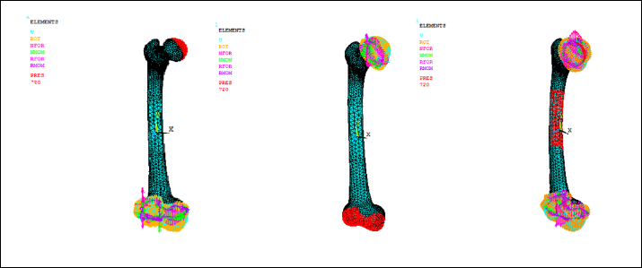
meshing operation was performed and boundary condition was applied. In real life bone can be broken under different loading condition. But in this paper three different boundary condition were applied.
a) Applying pressure from upper side while restraint the bottom of femur bone
b) Applying the pressure on bottom side while re- straint the upper end of femur bone
c) Applying the pressure on centre of bone while re- straint upper and lower end of femur bone
In this paper the average weight of a person 72kg was used. The following material properties were used for linear static analysis [4].
ρ=2000kg/m3 E= 2.130E9 Pa υ= 0.3
4 RESULTS AND DISCUSSION
In the first case, pressure was applied on the upper side of femur bone while epicondyle was restrained (displacement boundary condition applied) as shown in Figure 2.
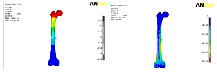
After performing simulation, deformations and Von Mises stresses were observed. The deformation and stress contour are shown in Figure 3. The maximum deformations occur on
the upper side of femur bone and minimum deformation oc-
IJSER
vide good results for linear, non linear, surface and solid mod-
el. Thickness was provided as real constant [6]. From the liter-
ature thickness of bone is described in the range of 4-8mm. In
this research 5mm thickness was used.
After selection of shell 181 element in triangular form,
curs on lower side of femur bone. The magnitudes of nodal
deformations were 0.052604m. The maximum stresses were on
the lower end of femur bone. The maximum stresses using
Von Misses criteria were 5.7688E4 Pa.
Figure 2 Pressure Applied on upper side (Left), Pressure Applied on Lower side (Center), pressure applied on Center of femur bone
IJSER © 2013 http://www.ijser.org
International Journal of Scientific & Engineering Research, Volume 4, Issue 12, December-2013 295
ISSN 2229-5518
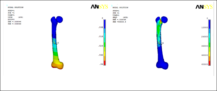
Figure 3 Deformations (Left) and Stresses (Right) when pressure applied on upper side of femur bone
IJSER
Figure 4 Deformations (Left) and Stresses (Right) when pressure applied on bottom side of femur bone
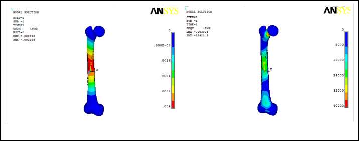
Figure 5 Deformations (Left) and Stresses (Right) when pressure applied on center of femur bone
IJSER © 2013 http://www.ijser.org
International Journal of Scientific & Engineering Research, Volume 4, Issue 12, December-2013 296
ISSN 2229-5518
In the second case, upper part of femur bone was restrained and pressure was applied on the epicondyle as shown in Fig- ure 2.
The stresses were observed using von misses criteria. The maximum stresses were on the neck of femur bone while min- imum stresses were on the lower part of the femur bone. The magnitude of maximum stress was 66596Pa. The maximum deformations were observed on the epicondyle and minimum on the upper part of the femur bone. The magnitude of maxi- mum deformation was 0.039046m. Stresses and deformations were observed using nodal solution as shown in Figure 4.
In the third case, simulation was performed by restraining the bone from bottom and top. The pressure was applied in the center of bone as shown in Figure 2.
The stresses were observed using von misses criteria. The maximum stresses were on the neck of femur bone while min- imum stresses were on the bottom of the bone. The magnitude of maximum stress was 59936Pa. The maximum deformation was found in the center while minimum deformation was on the epicondyle and on the head of femur bone. The magnitude of maximum deformation was 0.003995m. Stress and defor- mation contours are shown in Figure 5.
In all three cases it has been observed that maximum de- formations are at that point where pressure is applied and
deformations decreases as we go away from the area of appli-
Three-Dimensional Simulation of Femur Bone and Implant in Femo- ral Canal using Finite Element method, International journal of mathematics and computers in simulation. Vol. 4, No. 4, 2010
[5] T. S. Antonio, M. Ciaccia and C. M. Karger, E. Casanova, Orienta- tion of orthotropic material properties in a femur FE model: A method based on the principal stresses directions, Medical Engi- neering & Physics, Elsevier, 2011
[6] ANSYS 10 Help
cation of pressure. Maximum stresses are located at restraint end and decreases towards free end. In the first and second case where pressure is applied at one end while restraint other end, bone is behaving as cantilever beam. In the case where pressure is applied in the centre of femur bone, it has been observed that magnitude of maximum deformation is 10 times lower than the other two cases.
CONCLUSION
In this paper a unique way of modeling and mechanical stress analysis of femur bone is focused. Modeling of Complex shape of femur bone is accomplished through the novel ap- proach using a 3D animated software Blender. Pro/ENGINEER is beneficial while transforming polygonal model into CAD model. Simulation was performed after im- porting CAD model of human femur bone into ANSYS. Stress and deformation distribution varies with boundary condition. It has observed that Maximum stresses and minimum defor- mations are located at restraint end femur bone which indi- cates cantilever beam behavior of femur bone. Results vary with the individual that are helpful for orthopedic surgeons.
REFERENCES
[1] D. Knudson, Fundamental of Biomechanics, springer, 2007
[2] L. Voo, M. Armand, and M.kleinberger, Stress Fracture Risk Analysis of the Human Femur Based on Computational Biomechanics, Johns Hopkins APL Technical Digest, Vol. 25, No. 3, pp. 223, 2004
[3] A. D. Sylvester, B. C. Merkl , and M. R. Mahfouz, Assessing A.L. 288-
1 femur length using computer-aided three-dimensional reconstruc- tion, Journal of Human Evolution 55 , pp.665–671, 2008
[4] S. Amornsamankul, K. Kaorapapong, and B. Wiwatanapataphee,
IJSER © 2013 http://www.ijser.org