International Journal of Scientific & Engineering Research, Volume 4, Issue 12, December-2013 856
ISSN 2229-5518
Ultra Low Power Electrophysiological Monitoring
System based on Android Platform
Jithin Krishnan, Niranjan D. Khambete (Dr), Antony Rajan, Biju Benjamin
Instrumentation Lab, Sree Chitra Tirunal Institute for Medical Sciences and Technology
An Institute of National Importance under Govt of India, Trivandrum, Kerala
Abstract—Development of in vivo electronic devices has been the top priority of medical device development for the past few years. In the context, diagnosis of the bio potential system of human body before and after the treatment plays a lead role. This paper is about a low ultra low power electrophysiological monitoring system which has its primary application in as front end circuitry for patient monitoring systems such as polysomnography, ICU monitoring etc. the system has its key features as low power operation, durability, battery based operation, high noise rejection capabilities, support for wireless integration, small size etc. The Data Acquisition part contains sensors for picking up the vital signs from the patients, signal conditioning circuits and a Bluetooth transceiver to transmit data wirelessly to the display device. The Display Device then displays the data received from the transmitter in a readable form and also logs the data into a excel form so that it can be taken out digitally and analyzed.
Index Terms—Diagnosis, biopotential system, data acquisition, wireless integration. Bluetooth, data logging
Acquisition System coupled with the electrodes to pick up vital
I. INTRODUCTION
Advances in low power microelectronic devices over the years have given a rapid boost in the field of biomedical instrumentation. Bioelectronics interfaces that are miniaturized,
signals from the human body. The system is equipped with an analog front end which facilitates the signal extraction and conditioning.
The system contains bioelectrodes depending upon the type
IJSER
light weight, low power, compatible with minimum interface
requirements etc has been come out research and development laboratories in the mean time. Nowadays medical device development is undergoing dramatic changes absorbing advancements in research areas such as wireless automation, transcutaneous energy transfer, on invasive cardiac support devices delivery, total artificial heart etc.
Conventional block diagram of a biopotential recording system is shown in figure 1.For decades monolithic amplifiers were used for measuring and recording electrophysiological signals. Due to the large time constant that was inherently present in the monolithic amplifier’s dynamics prevent the sharing of a single electrode between multiple electrodes. So multiple amplifiers, one per channel is used typically for multichannel systems.
Jithin Krishnan, Sree Chitra Tirunal Institute for Medical Sciences and
Technology, Trivandrum mail: jithinkrishnan@sctimst.ac.in Niranjan D. Khambete, Sree Chitra Tirunal Institute for Medical Sciences and Technology, Trivandrum mail:
niranjan@sctimst.ac.in
Biju Benjamin, Sree Chitra Tirunal Institute for Medical Sciences and
Technology, Trivandrum mail: bijube njaminhere@gmail.com
Antony Rajan, Sree Chitra Tirunal Institute for Medical Sciences and
Technology, Trivandrum mail
: antonyaquinas@gmail.com
Figure 1 explains the basic block diagram of a data acquisition front end. The system consists of a Data
of biopotential that is to be acquired, front end instrumentation
amplifiers for the initial pick up of the signals, a signal
Fig 1. Biopotential Acquiring System
conditioning circuit for noise removal, gain etc. The signal from the signal conditioning circuit is converted to a digital signal by means of an analog to digital converter (ADC).Since we need to transmit the signal via any serial communication means we can opt for an ADC inside any of the microcontroller since it has dedicated serial communication capabilities. The Bluetooth transmitter serially transmits the digital data to the android device and the device plots the data in visual format.
Table 1 shows the electrical characteristics of commonly acquired electrophysiological signals that are commonly acquired during diagnosis and treatment. Single unit recording, provides finest spatial resolution of the signals but they typically incur relatively higher power consumption due to wide amplifier bandwidth required and high resulting data rate.
IJSER © 2013 http://www.ijser.org
International Journal of Scientific & Engineering Research, Volume 4, Issue 12, December-2013 857
ISSN 2229-5518
TABLE 1
Characteristics of Electrophysiological Signals
Technical specifications of the biopotential signals are to be considered while designing amplitude based recording amplifier. Cellular action potentials which fall in frequency range of 100 Hz to 7 KHz band have amplitude of up to 500
µv. Local Field Signals that come under low frequency band (<1 Hz)typically have an amplitude of up to 5 mV. There are some considerations in analog signal processing while discussing about bio potential amplifiers. Low amplitude levels of biopotential signals limit the gain of biosignal amplifiers to around 100 up to a few KHz. DC offsets which are introduced by artifacts at electrode tissue interface implies a need for offset cancellation or ac coupling. To limit the signal attenuation at electrode tissue interface the input impedance of the amplifiers should be very high in order of few MΩs. to contain the rise in temperature due to power dissipation the amplifier should draw only a minimal current. To deal with interference and power supply noise which are inevitable in amplifier designs sufficient Common Mode Rejection and
decrease the negative charge towards zero which activates the mechanisms in the cell that causes cell to contract is called depolarization. During each heartbeat a consistently paced wave of depolarization which is generated by the SA node- sinoartial node spreads throughout the atrium through purkinjee fibres to the ventricles.This is reflected as small rises and falls in the potential between electrodes placed across heart .this is displayed as a wavy line either on a screen or on a paper.[1][2]
The basic ECG signal will look like in Fig :2
Power supply rejection has tIo be ensJured. SER
II. BIO POTENTIAL AMPLIFIERS
A biopotential amplifier’s main function is to pick any signal of biological origin and amplify it so that it can be further processed analyzed, displayed or recorded. Normally those amplifiers alter the amplitude levels and there by power also so these can be called as voltage amplifiers or power amplifiers as well. Biopotential amplifiers when used for isolating the load, they only provide current gain leaving the voltage levels intact.
Most often bipolar electrodes are used to acquire biopotential signals. Speaking with respect to ground these electrodes will be electrically located in a symmetric manner. That makes the choice of amplifier to be a differential one. Distortions in the symmetry with respect to ground can introduce common mode voltage fluctuations in the amplifier so the amplifier should have high common mode rejection ratios to deal with the interference due to common mode signal. Biopotential amplifiers have additional requirements that are application specific to various signal types and its characteristics which are discussed below.
II.1 ECG-Electrocardiograph Amplifier
Heart health of a person can be easily identified from ECG waveform like arterial fibrillation can be detected from distortions in P wave.
II.1.1 Basic Principles of ECG
Small electrical changes are introduced in human skin when the heart muscle depolarizes during the heart beat which is detected and amplified by the ECG amplifier. There is a membrane potential across the cell membrane usually called as cell potential which is usually negative when the heart is at rest. Through influx of positive ions Na+ and Ca++ will
Fig 2: ECG Signal
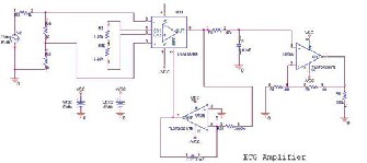
Fig 3: Schematic Diagram of the ECG amplifier. II.2 EMG- Electromyograph Amplifier
Electromyography (EMG) measures muscle response or electrical activity in response to a nerve’s stimulation of the muscle. The test is used to help detect neuromuscular abnormalities. Instead of conventional needle electrodes we are using surface electrodes along with the designed highly versatile bio amplifier system to pick up the surface EMG signals. The electrical activity picked up by the electrodes is then displayed on an oscilloscope (a monitor that displays electrical activity in the form of waves). An audio- amplifier is used so the activity can be heard.EMG measures the electrical activity of muscle during rest, slight contraction and forceful contraction. Muscle tissue does not normally produce electrical signals during rest.[3]
IJSER © 2013 http://www.ijser.org
International Journal of Scientific & Engineering Research, Volume 4, Issue 12, December-2013 858
ISSN 2229-5518
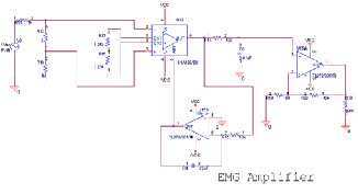
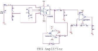
Fig 4: Schematic Diagram of the EMG amplifier. II.3 EEG –Electroencephalograph.
Electroencephalography (EEG) is the recording brains electrical activity over the scalp. Neurons in the brain produce voltage level variation due to ionic flow variations and thus producing EEG. In clinical contexts, EEG refers to the recording of the brain's spontaneous electrical activity over a short period of time, usually 20–40 minutes, as recorded from multiple electrodes placed on the scalp. Generally the spectral content in the EEG-ie the type of neural oscillations inside brain is taken into account for diagnosis. In neurology, the studies in EEG are mainly on Epileptic studies since variations in EEG signals are clearly
Fig 6: Comparison between frequency response curve of ECG, EEG and EMG signals.
IV. PCB DESIGN
The PCB of Bio-signal Amplifier is Double Sided one with dimension 15 x 18 x 1.6 mm. The PCB is provided with a mounting hole at the centre, so that PCB can use in a stacked manner for multiple channel application. The material used is FR4 with 35 uM copper thicknesses. The surface finish used is HASL (Sn-Pb) (Hot Air Solder Leveling). The PCB is routed with trace width 8 mil for signals and 12 mil for Power with a Track to Track spacing of 8 mil. The VIA used is 12/24 (drill/pad size, in mils).Thermal relief spoke width is 12 mil. The ground is poured on both side of the board for better connectivity and noise immunity. [8]
IJSER
depicted in case of Epilepsy. EEG can be used as a
secondary diagnosis method for, coma, encephalopathies, and brain death. For studies related to Sleep disorders and sleep apnea EEG signals are being put on to use widely. The detection of sleep and differentiation between the REM and TEM stages of sleep is identified from the alpha waves of EEG only. As a first line method EEG can be used as a tagline feature for detection of tumors, stroke and other focal; brain disorders. Despite limited spatial resolution, EEG continues to be a valuable tool for research and diagnosis, especially when millisecond-range temporal resolution (not possible with CT or MRI) is required.[2][3]
Fig 5: Schematic Diagram of EEG amplifier
III. SIMULATION RESULTS.
The simulation results of three amplifiers are done using Pspice tool from cadence. The transient response and ac sweep analysis were performed to verify the amplification factor and frequency responses which are shown in the figure below.
The PCB is designed in such way that to meet signal
integrity needs. The board contains two connectors input and output connector and the power connector. The input lines are routed differentially for better noise immunity. An additional provision for shielding the circuit is also provided on the board through the mounting hole. So we can easily connect the PCB to chassis using a M2 earthing tag.
Fig 7: Bottom Layer
Routing of PCB
Fig 8: Top Layer Routing of PCB
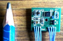
Fig 9: Actual Populated PCB. (Size comparison with a standard pencil tip)
IJSER © 2013 http://www.ijser.org
International Journal of Scientific & Engineering Research, Volume 4, Issue 12, December-2013 859
ISSN 2229-5518
V. BLUETOOTH TRANCEIVER
The Bluetooth transceiver module used for the setup is RN42 series from spark fun electronics-Bluesmirf series. The RN42 is a small form factor, low power, highly economic Bluetooth radio for OEM’s adding wireless capability to their products. The RN42 supports multiple interface protocols, is simple to design in and fully certified, making it a complete embedded Bluetooth solution. The RN 42 is functionally compatible with RN 41. With its high performance on chip antenna and support for Bluetooth® Enhanced Data Rate (EDR), the RN42 delivers up to 3 Mbps data rate for distances to 20M. The RN-
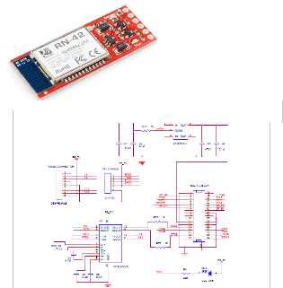
42 also comes in a package with no antenna (RN-42-N). Useful when the application requires an external antenna, the RN-42-N is shorter in length and has RF pads to route the antenna signal.
Figure 10: Spark fun Bluetooth Module
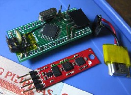
Fig 12: Bluetooth module and Microcontroller board
VII. RESULTS
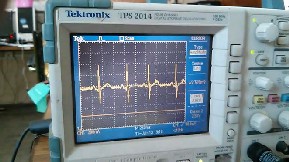
The PCB is fabricated as a four layer PCB with two routing layers and two power planes. The circuit was tested clinically with volunteers and indigenously developed electrodes that are developed in our laboratory only. Fig 13 shows the actual screen shot of an ECG wave form on Tektronix DSO.
Fig 13: Real time acquisition on DSO.
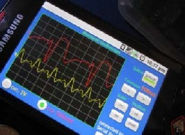
Figure 14 shows the real time data acquisition on the android device for a two channel system.the device used was
Samsung mobile phone running on android 2.3 (Ginger bread ).
IJSER
Fig 11: Wiring Diagram of the Transceiver with
Microcontroller
VI. ANDROID PLATFORM AND SOFTWARE
The software for the android device is developed in Java platform using Windows SDK bundle for android. The display includes a canvas were the waveforms are being plotted. Figure
6(b) shows the data acquired in the screen and how it’s displayed. It contains a button to connect to the Bluetooth module and to pair with it. It uses the well known UUID
00001101-0000-1000-8000-00805F9B34FB for the Bluetooth
RFCOMM/SPP
Fig 14: Software running on Android Device
VIII. CONCLUSION AND FUTURE WORK
The system as such is made for acquiring of bio potential data but can be extended to other domains also. The microcontroller used can be replaced with a more sophisticated system like to include analog front end processing also. Thereby a much reduction in size can be achieved for the front end side. The Bluetooth module used can be replaced with SMD modules also.
REFERENCES
[1]. Jithin Krishnan, Niranjan D Khambete (Dr.) and Biju B. (2013) “A Real time Data Acquisition and Monitoring Device for Medical Applications based on Android Platform”. Intnl Journal of
Advanced Computer research, Vol-3, Issue-12, Sept 13, pp 47-51.
[2]. Jithin Krishnan, Niranjan D Khambete (Dr.) , Biju B,Antony
Rajan (2013) “Low Power Multiparameter Biopotential Amplifier
IJSER © 2013 http://www.ijser.org
International Journal of Scientific & Engineering Research, Volume 4, Issue 12, December-2013 860
ISSN 2229-5518
System ”. Intnl Journal of Science and Research, Vol-2, Issue-11, Nov 13.
[3]. CHRISTOV, I. I., and DOTSINSKY, I. A. (1988): 'New approach to the digital elimination of 50 Hz interference from the electrocardio- gram', Med. Biol. Eng. Comput, 26, pp. 431 -434
[4]. DASKALOV, I. K., DOTSINSKY, I. A., and CHRISTOV, I. I. (1998): ‘Developments in ECG acquisition, preprocessing, parameter measurement and recording', IEEE Eng. ivied. Biol., 17, pp. 50 – 58
[5]. Design of Ultra-Low Power Biopotential Amplifiers
for Biosignal Acquisition Applications. Fan Zhang, Student Member, IEEE, Jeremy Holleman, Member, IEEE, and Brian P. Otis, Senior Member, IEEE. IEEE TRANSACTIONS ON BIOMEDICAL CIRCUITS AND SYSTEMS, VOL. 6, NO. 4, AUGUST 2012.
[6]. R. Harrison, “The design of integrated circuits to observe brain activity,”Proc. IEEE, vol. 96, pp. 1203–1216, Mar. 2008.
[7]. W. Wattanapanitch, M. Fee, andR. Sarpeshkar, “An energy- efficient micropower neural recordingamplifier,”IEEE Trans. Biomed. Circuits. Syst., vol. 1, no. 2, pp. 136–147, 2007
[8]. B. Razavi,Designof Analog CMOS Integrated Circuits. Noida, India: Tata McGraw-Hill, 2000

Biju Benjamin is working as Technical assistant (Instruments) in Biomedical Technology Wing Sreechitra Tirunal Institute for Medical Sciences
& Technology, Thiruvanathapuram, Kerala. For
Last 8 years he has been working in the Field of
Electronics Testing, Simulation & PCB Design.

Antony Rajan received his M Tech Degree from IIT Bombay in 2013. His areas of interest are signal processing, embedded system design and biomedical instrumentation. He is currently doing research in biomedical instrumentation, focusing on development of ambulatory vital sign monitor.
[9]. Medical Instrumentation Application and Design, John G Webster, ISBN-10: 0471676004 | ISBN-13: 978-0471676003 |
Edition: 4
[10]. A Practical Guide to High-Speed Printed-Circuit-Board
Layout By John Ardizzon

Jithin Krishnan received his M Tech Degree from
Cochin University of Science and Technology in
2012.His area of interests is VLSI, Embedded systems and Bio Medical Instrumentation. He is
currently doing research in biomedical instrumentation focusing on data acquisition systems and sophisticated medical devices
development. He is a IEEE member for more than 5 years and is currently review committee member for IEEE Standards Association for Asia-Pacific.

Dr. Niranjan D. Khambete has B. E. in Instrumentation Engineering, M. Tech. in Biomedical Engineering and PhD in Engineering and has been actively contributing to the Medical Device R&D needs of the country for last two decades. He worked as a team leader to successfully complete the indigenous technology
development and commercialization of Concentric Needle
Electrodes. On research front, Dr. Khambete works on movement artifact free apnea monitors for early detection of sleep disordered breathing and bio-impedance spectroscopic measurement systems for early detection of cervical cancer in women and monitoring cell growth in tissue engineered organs . In recent years, Dr. Khambete has also focused his efforts towards spreading awareness about the Clinical Engineering Profession and promoting safe use of medical equipment in hospitals. In 2010, he received the WHO Patient Safety Award for his paper on medical device safety in hospitals at a conference in London. In 2011, the American College of Clinical Engineering gave him Antonio Hernandez International Clinical Engineering Award, for his leadership and commitment to the growth of Clinical Engineering Profession in India.
IJSER © 2013 http://www.ijser.org