The research paper published by IJSER journal is about UAV Flight Control Using SONAR 1
ISSN 2229-5518
UAV Flight Control Using SONAR
T.A. Mithu, M. Hossain, S. Faruque
Abstract— There are several flight control techniques of Unmanned Aerial Vehicle (UAV). This paper presents such a technique by using SONAR (Sound Navigation and Ranging). In this method, human operator transmits signal from ground station to the aircraft. After receiving the ground signal, different frequencies of sound are generated from the cockpit of the aircraft which then pass through the metallic body of vehicle. Different functional units of the aircraft respond to the respective sound signal and convert sound energy into electrical form and accordingly perform the assigned operation by using it.
Index Terms— Aircraft, Sound, Propagate, Signal, Flight, Frequency, SONAR, Transmitter, Microphone.
1 INTRODUCTION
—————————— ——————————
vibration is propagated through the movement of atoms creating kinetic energy. [6]
An unmanned aerial vehicle (UAV), also known as
unmanned aircraft system (UAS), remotely piloted aircraft (RPA) or unmanned aircraft, is a powered, aerial vehicle that does not carry a human operator on board. It uses aerodynamic forces to provide vehicle lift, can fly autonomously based on pre-programmed flight plans or more complex dynamic automation systems or be piloted remotely. [1,2] Their largest use is found in military applications (i.e. combat search and rescue, target and decoy, reconnaissance etc.). Other than this, UAVs are used in research and development, civil and commercial applications such as aerial photography, crop monitoring and spraying, coastline and sea-lane monitoring, pollution and land monitoring, surveillance for illegal imports, power line inspection, fire services and forestry fire detection etc. [3]
There are several ways of controlling the UAV. Generally, flight control mechanism of UAV uses space based global navigation satellite system (GNSS) or global positioning System (GPS) or inertial navigation system (INS) that provides location and time information. Ground control segment includes remote control receiver, data link, INS, flight planning application, flight analysis software etc. to communicate with the autopilot board on aircraft. [4] LASER guiding technology is also used for long distance operation. In this study, we are going to present another technique of UAV flight control which is by using SONAR.
SONAR (acronym for Sound Navigation And Ranging) is a technique that uses sound propagation to navigate, communicate with or detect other objects. [5] In our case, we’ve used an important property of sound to navigate UAV that is, propagation of sound through the metallic
body. When sound is passed through a metallic bar, sound
2 TECHNICAL DETAILS
2.1 Airplane parts and function:
Major functional units and technical parts of the aircraft needed to control the UAV, are discussed below:
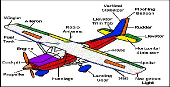
Fig 1: Airplane Parts (Basic Aircraft) 7
● Aileron: moving parts attached to the rear edge of an aircraft's wing that helps the aircraft to bank/turn/roll.
● Elevator: moving parts on the horizontal stabilizer of an
aircraft that move up or down to make the aircraft climb or descend.
● Rudder: moving parts on the vertical stabilizer that turn
(yaw) the aircraft left or right.
● Propeller: two or more twisted blades that pull an airplane forward as they turn. Blades have the same shape as wings.
● Cockpit: command and control unit of the aircraft.
● Engine: the part of an aircraft that provides power to move the aircraft through the air.
● Radio Antenna: allows pilots to keep in radio contact
with ground control.
● Horizontal Stabilizer: airfoils located on the tail of an
IJSER © 2012
http://www.ijser.org
The research paper published by IJSER journal is about UAV Flight Control Using SONAR 2
ISSN 2229-5518
aircraft that help to maintain a straight, horizontal path through the air.
● Vertical Stabilizer: airfoils located on the tail of an
aircraft that help to maintain a straight, vertical path through the air.
● Landing Gear: the wheels on an airplane so it can land and taxi.
● Flaps: found on the wing closer to the fuselage than the ailerons. They can be lowered to provide more lift at slower speeds so an airplane can take off and land. [7, 8]
2.2 Flight control technique of UAV:
We have followed 2-phase control architecture to achieve our goal. We used ground control system (by human operators) in the first phase and airborne control (within the aircraft) in the second phase (fig-3).
Phase 1- Ground control:
A hand held radio controlled transmitter is used having number of channels determined by the number of mechanical servos that have been installed in the aircraft. The most basic airplane, with no ailerons, needs a 3-channel radio transmitter in order to control the throttle, rudder, and elevator. Four or more channel transmitter is used for complex model or larger scale planes. The radio shown in the figure-2 is a six-channel transmitter. It takes four channels (controls for throttle, rudder, elevator and aileron) to fly the plane, which leaves two channels open for using flaps, retractable landing gear, or anything that requires a servo such as opening cargo doors, dropping bombs, operating remote cameras, lights etc. Different band of frequencies are transmitted by the different channels of the transmitter. A receiver in the aircraft responds to the transmitted signal and controls the corresponding servos that move the control surfaces of aircraft based on the position of joysticks on the transmitter, which in turn affect
the orientation of the plane. [9, 10]

through the filter. Then microphone converts sound signal into electrical form and amplify it. This electrical energy is used to run a motor or control a servo of the aircraft.
Fig 2: Six-Channel radio transmitter.11
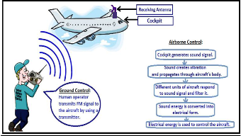
Fig 3: Complete diagram of UAV flight control technique.
Phase 2- Airborne control:
Airborne control starts after receiving the signal from the
ground station. Here we introduce the concept of SONAR. There is a receiving antenna and a speaker connected with cockpit of the aircraft. Cockpit receives the RF signal coming from transmitter, converts it into sound by using the speaker. Sound creates vibration in the metallic body of the aircraft which propagates through it and eventually reaches to every functional unit of the aircraft where microphone, motor, band pass filter and other circuits are connected. When desired signal is received, it passes
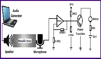
Fig 4: Experimental setup of UAV flight control using
SONAR.
3 LAB DEMONSTRATION
3.1 Necessary Instruments:
● PC with Audio generator software,
● Speaker and High sensitive Microphone,
● Breadboard, Resistors and connecting wires,
● IC: OPAMP LM741, Power Transistor BD135 (Gain
IJSER © 2012
http://www.ijser.org
The research paper published by IJSER journal is about UAV Flight Control Using SONAR 3
ISSN 2229-5518
around 100),
● 10 Volt Battery and dual power supply for OPAMP,
● Metallic body/plate made of Aluminium or Steel,
● DC motors (2V or 6V).
3.2 Experimental:
We used a PC with Audio generator software which can create sound of frequency up to 15 KHz. We kept the speaker of the PC on a metallic plate. On the other side of the plate a high sensitive microphone was placed (fig-4). When sound was generated, it vibrated the plate and passed to the other side where it was picked up by the microphone. The microphone then converted sound energy into electrical form. As the electric signal was very low in strength (order of millivolt), we used an OPAMP with high gain to amplify the signal. This amplified signal was passed through the power transistor that ran a motor connected with the collector of transistor.
4 CONCLUSION
Every part of the aircraft is controlled by motor. In our experiment, we have achieved our mission by successfully rotating the motor using SONAR. That indicates we can use SONAR instead of fuel to drive our aircraft. On the other hand, the reservoir of the fuel in this world is limited. So in future, use of SONAR will be effective, economic and easily available as well as environment friendly.
In this process, sound is propagated through the body of the aircraft using no wires or cables. Weight of the aircraft will be greatly reduced for not using fuels and wires which makes the flight control of UAV easier. In SONAR system overall mechanism in generation, propagation and conversion of sound waves is much easier. Conversion of sound waves into electrical energy without using fuel is cost-effective. Besides, with this technique the risk of fuel induced firing and other unwanted accidents can be avoided and frequent landing of aircraft in different airports for refilling of fuel can be minimized.
There are some difficulties of SONAR system. Sound wave after generation progressively become weaker as it propagates through the body of the aircraft. So, high sensitive microphone (i.e. piezoelectric microphone) is required to pick up sound in greater intensity to produce desired action. In general, the body of the aircraft is made by Aluminium or Titanium alloys. But for UAV flight control using SONAR, aircraft’s body should be made with
metallic substances highly sensitive to sound waves.
Another difficulty may be due to interference of sound waves with the noise made by the aircraft itself or by external sources, which needs to be eliminated.
ACKNOWLEDGEMENT:
The authors wish to thank US Fulbright Scholar Program for supporting this work.
REFERENCE:
[1] http://www.theuav.com/
[2] http://en.wikipedia.org/wiki/Unmanned_aerial_vehicle
[3] Austin R., ‘Unmanned Aircraft Systems’; UAVS Design,
Development and Deployment, John Wiley & Sons, Inc.
[4] http://www.galaxynav.com/FCS.pdf [5] http://en.wikipedia.org/wiki/Sonar [6] http://www.ndt-
ed.org/EducationResources/HighSchool/Sound/
[7] http://downloads.cas.psu.edu/4h/AerospaceSupp/index.htm [8] http://www.grc.nasa.gov/WWW/k-12/airplane/airplane.html [9] http://www.hooked-on-rc-airplanes.com/rc-airplane-
controls.html
[10] http://en.wikipedia.org/wiki/RC_airplane
[11] http://rcplanesforbeginners.net/remote-controlled-airplanes/
AUTHORS BIOGRAPHY:
T.A. Mithu received B.Sc. (Hons.) degree (2011) and completed M.Sc. (2012) in Applied Physics, Electronics & Communication Engineering from Dhaka University, Bangladesh. Currently he is pursuing Master’s degree in Computer Applications from Jawaharlal Nehru Technological University in Hyderabad, India.
M. Hossain obtained B.Sc. (Hons.) degree (2011) and completed M.Sc. (2012) in Applied Physics, Electronics & Communication Engineering from Dhaka University, Bangladesh. His area of interest includes Wireless Communication.
Dr. S. Faruque received B.Sc. in Physics and M.Sc. in Applied Physics from Dhaka University, Bangladesh in 1969 and 1970 respectively. He received M.A.Sc. and PhD degrees, both in Electrical Engineering, from the University of Waterloo, Ontario, Canada in 1976 and 1980 respectively. Then he contributed in telecom industries at various roles for 20 years. Since 2002 he has been working as an Associate Professor in Electrical Engineering department at University of North Dakota, Grand Forks, North Dakota, USA.
IJSER © 2012
http://www.ijser.org