The research paper published by IJSER journal is about Twice -Band Microstrip Hexagonal Slotted Patch Antenna for Microwave Communication 1
ISSN 2229-5518
Twice -Band Microstrip Hexagonal Slotted Patch Antenna for Microwave Communication Bipa Datta#1, Arnab Das #2, Samiran Chatterjee#3,
#1,2,3ECE Deptt., Brainware Group of Institutions, Barasat, West Bengal University of Technology, Kolkata, West
Bengal, India
1bipa.datta@gmail.com, 2u_call_arnab@yahoo.co.in, 3samiranengineer@gmail.com
Moumita Mukherjee*4,
*4Centre for Millimeter wave Semiconductor Devices and Systems, University of Calcutta, West Bengal, India
4mm_drdo@yahoo.com
Santosh Kumar Chowdhury^5
^5West Bengal University of Technology, JIS College of Engineering, West Bengal, India
5santoshkumarchowdhury@gmail.com
Abstract—A single layer, single feed compact slotted patch antenna is thoroughly simulated in this paper. Resonant f requency has been reduced drastically by cutting three equal slots which are same hexagonal structure at the upper right, upper left and lower left corner from the conventional microstrip patch antenna. It is shown that the simulated results are in acceptable agreement. More importantly, it is also shown that the differentially-driven microstrip antenna has higher gain of simulated 3.24 dBi at 9.91 GHz and 0.14 dBi at 13.61 GHz and
beamwidth of simulated 163.190 at 9.91 GHz and 122.100 at 13.61 GHz of the single-ended microstrip antenna. Simulated antenna size has been reduced by 48.11% with an increased frequency ratio when compared to a Conventional microstrip patch antenna.
Index Terms — Compact, Patch, Slot, Resonant frequency, Bandwidth.
—————————— ——————————
right, upper left and lower left corner from the conventional
microstrip patch antenna, to increase the return loss and gain-
1. INTRODUCTION
N recent years, demand for small antennas on wireless communication has increased the interest of research work
on compact microstrip antenna design among microwave and wireless engineers [1-6]. Microstrip antennas have many unique and attractive properties – low in profile, light in weight, compact and conformable in structure, and easy to fabricate to support the high mobility necessity for a wireless telecommunication device and for high resolution mapping for radar communication, a small and light weight compact microstrip antenna is one of the most suitable application. The development of antenna for wireless communication also requires an antenna with more than one operating frequency. This is due to many reasons, primarily because of various wireless communication systems and many telecommunication operators use various frequencies. In its most fundamental form, a Microstrip Patch antenna consists of a radiating patch on one side of a dielectric substrate which has a ground plane on the other side. Therefore one antenna that has multiband characteristic is more desirable than having one antenna for each frequency band.
Most effective technique is cutting slot in proper position
on the microstrip patch. In this paper includes cutting three
equal slots which are same hexagonal structure at the upper
bandwidth performance of the simulated antenna (Figure 2). The antenna has become a necessity for many applications in recent wireless communication such as radar, microwave and space communication. To reduce the size of the antenna substrates are chosen with higher value of dielectric constant [7-9]. Our aim is to reduce the size of the antenna as well as increase the operating bandwidth. The proposed antenna (substrate with εr = 4.4) has a gain of 3.24 dBi and presents a size reduction of 48.11% when compared to a conventional microstrip patch (10mm X 6mm). The simulation has been carried out by IE3D [14] software which uses the MoM method. Due to the small size, low cost and low weight this antenna is a good entrant for the application of X-Band microwave communication and Ku-Band RADAR communication.
The X band belongs to in the microwave radio region of
the electromagnetic spectrum. It is defined by an IEEE standard for radio waves and radar engineering with frequencies that ranges from 8.0 to 12.0 GHz. The X band is used for short range tracking, missile guidance, marine, radar and air bone intercept. Especially, it is used for radar communication ranges roughly from 8.29 GHz to 11.4 GHz. The Ku-Band belongs to in the microwave radio region of the electromagnetic spectrum. It is defined by an IEEE standard for radio waves and radar engineering with frequencies that ranges from 12.0 to 18.0 GHz [10-11]. The Ku
IJSER © 2012
http://www.ijser.org
The research paper published by IJSER journal is about Twice -Band Microstrip Hexagonal Slotted Patch Antenna for Microwave Communication 2
ISSN 2229-5518
band [12] is used for high resolution mapping and satellite altimetry. Specially, Ku Band [13] is used for tracking the satellite within the ranges roughly from 12.87 GHz to 14.43
GHz.
2. ANTENNA DESIGN
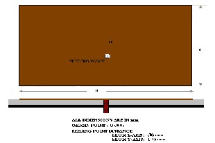
The configuration of the conventional printed antenna is
shown in Figure 1 with L=6 mm, W=10 mm, substrate (PTFE)
thickness h = 1.6 mm, dielectric constant εr = 4.4. Coaxial probe-feed (radius=0.5mm) is located at W/2 and L/3.
Assuming practical patch width W= 10 mm for efficient radiation and using the equation [6],


√ …1
Where, c = velocity of light in free space. Using the following
equation [9] we have determined the practical length L = 6
mm.
L=Leff - 2∆L …2
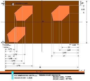
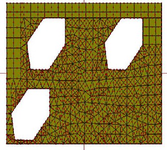
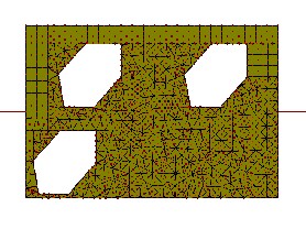
and lower left corner from the conventional microstrip patch antenna and the location of coaxial probe-feed (radius=0.5 mm) are shown in the figure 2.
Figure 2: Simulated Antenna configuration
where,


[
–
] …3
3. RESULTS AND DISCUSSION
Simulated (using IE3D [14]) results of return loss in conventional and simulated antenna structures are shown in
and


( ) …4

( √( ))

[ ] ...5
√
Figure 3-4. A significant improvement of frequency reduction is achieved with simulated antenna compared to its conventional antenna counterpart.
Where, Leff = Effective length of the patch,
∆L/h =Normalized extension of the patch length,
εreff = Effective dielectric constant.
Figure 1: Conventional Antenna configuration
Figure 2 shows the configuration of simulated printed antenna designed with similar PTFE substrate. Three equal slots which are same hexagonal structure at the upper right, upper left
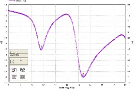
Figure 3: Antenna 1 Return Loss vs. Frequency (Conventional
Antenna)
IJSER © 2012
http://www.ijser.org
The research paper published by IJSER journal is about Twice -Band Microstrip Hexagonal Slotted Patch Antenna for Microwave Communication 3
ISSN 2229-5518
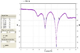
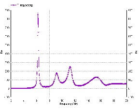
Figure 4: Slotted Antenna Return Loss vs. Frequency (Slotted Antenna)
In conventional antenna, return loss of about -7.0 dB is
obtained at 13.39 GHz. Comparative analysis of Fig.3 &4
depicts that for the conventional antenna (fig.3), there is
practically no resonant frequency at around 9.25 GHz with a return loss of around -6 dB. For the simulated antenna there is
a resonant frequency at around 9.91 GHz with the return loss as high as -17.1 dB.
Due to the presence of slots in simulated antenna resonant
frequency operation is obtained with large values of frequency
ratio. The first and second resonant frequency is obtained at
f1= 9.91 GHz with return loss of about -17.1 dB and at f2 = 13.61
GHz with return losses -34dB respectively. Corresponding 10
dB bandwidth is obtained for Antenna 2 at f1 and f2 are 696.80
MHz and 1.48 GHz, respectively.
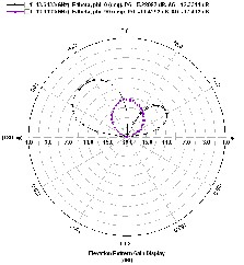
The simulated E plane and H-plane radiation patterns are shown in Figure 5-12. The simulated E plane (Total) radiation pattern of simulated antenna for 9.91 GHz is shown in figure
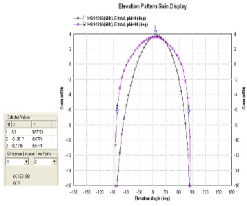
5.
Figure 5: E-Plane (Total) Radiation Pattern for Slotted Antenna at 9.91 GHz
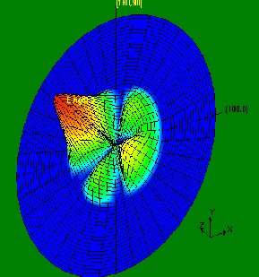
The simulated E plane (Total) radiation pattern (3D) of simulated antenna for 9.91 GHz is shown in figure 6.
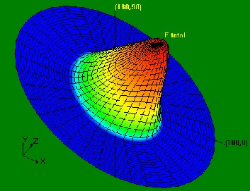
Figure 6: E-Plane (Total) Radiation (3D)Pattern for Slotted Antenna at 9.91 GHz
The simulated current distribution pattern of simulated antenna for 9.91 GHz is shown in figure 7.
Figure 7: Current Distribution Pattern for Slotted Antenna at 9.91 GHz
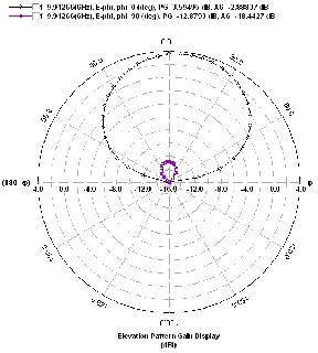
The simulated E plane radiation pattern of simulated antenna for 9.91 GHz is shown in figure 8.
IJSER © 2012
http://www.ijser.org
The research paper published by IJSER journal is about Twice -Band Microstrip Hexagonal Slotted Patch Antenna for Microwave Communication 4
ISSN 2229-5518
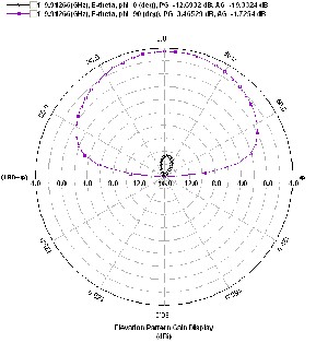
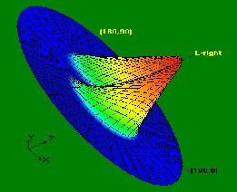
Figure 10: E-Plane Radiation Pattern (3D) for slotted antenna at 9.91 GHz
The simulated H plane radiation pattern (3D-view) of slotted antenna for 9.91 GHz is shown in figure 11.
Figure 8: E-Plane Radiation Pattern for Slotted Antenna at 9.91 GHz
The simulated H plane radiation pattern of simulated antenna for 9.91 GHz is shown in figure 9.
Figure 11: H-Plane Radiation Pattern (3D) for slotted antenna at 9.91 GHz
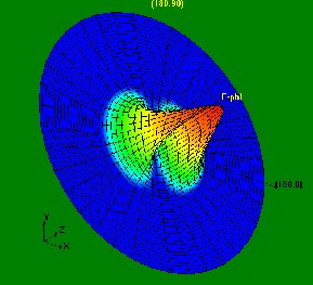
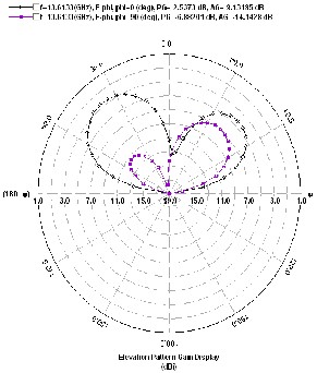
The simulated E plane (Total) radiation pattern of simulated antenna for 13.61 GHz is shown in figure 12.
Figure 9: H-Plane Radiation Pattern for slotted Antenna at 9.91 GHz
The simulated E plane radiation pattern (3D-view) of Slotted
Antenna for 9.91 GHz is shown in figure 10.
Figure 12: E-Plane (Total) Radiation Pattern for slotted antenna at 13.61GHz The simulated E plane (Total) radiation pattern (3D) of simulated antenna for 13.61 GHz is shown in figure 13.
IJSER © 2012
http://www.ijser.org
The research paper published by IJSER journal is about Twice -Band Microstrip Hexagonal Slotted Patch Antenna for Microwave Communication 5
ISSN 2229-5518

Figure 13: E-Plane (Total) Radiation Pattern (3D) for slotted antenna at 13.61
GHz
The simulated current distribution pattern of simulated antenna for 13.61 GHz is shown in figure 14.
Figure 16: H-Plane Radiation Pattern for slotted antenna at 13.61GHz
The simulated E plane radiation pattern of slotted antenna
(3D-view) for 13.61 GHz is shown in figure 17.
Figure 14: Current Distribution for slotted antenna at 13.61 GHz
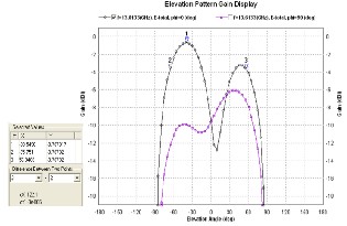
The simulated E plane radiation pattern of simulated antenna for 13.61 GHz is shown in figure 15.
Figure 17: E-Plane Radiation Pattern (3D) for slotted antenna at 13.61 GHz
The simulated H plane radiation pattern of slotted antenna
(3D-view) for 13.61 GHz is shown in figure 18.
Figure 15: E-Plane Radiation Pattern for slotted antenna at 13.61GHz
The simulated H plane radiation pattern of slotted antenna for
13.61 GHz is shown in figure 16.
IJSER © 2012
http://www.ijser.org
The research paper published by IJSER journal is about Twice -Band Microstrip Hexagonal Slotted Patch Antenna for Microwave Communication 6
ISSN 2229-5518
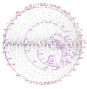
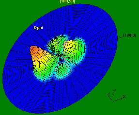
Figure 18: H-Plane Radiation Pattern (3D) for slotted antenna at 13.61 GHz
The simulated frequency vs. real part of the function for slotted antenna is shown in figure 19.
Figure 19: Frequency vs. real function for slotted antenna
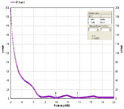
The simulated frequency vs. VSWR for slotted antenna is shown in figure 20.
Figure 20: VSWR for slotted antenna
The simulated Smith Chart for slotted antenna is shown in figure 21.
Figure 21: Smith Chart for slotted antenna
All the simulated results are summarized in the following
Table1 and Table2.
TABLE I:
SIMULATED RESULTS FOR ANTENNA 1 AND 2
ANTENNA STRUCTURE | RESONANT FREQUENCY (GHZ) | RETURN LOSS (dB) | 10 DB BAND- WIDTH (GHZ) |
Conventional | f1= 13.39 | -7.00 | NA |
Slotted | f1= 9.91 | -17.1 | 0.6968 |
Slotted | f2= 13.61 | -34 | 1.4826 |
TABLE II:
SIMULATED RESULTS FOR ANTENNA 1 AND 2
ANTENNA STRUCTURE | RESONANT FREQUENCY (GHZ) | 3 DB BEAM- WIDTH (0) | ABSOLUTE GAIN (dBi) |
Conventional | f1= 13.39 | NA | NA |
Slotted | f1= 9.91 | 163.19 0 | 3.24 |
Slotted | f2= 13.61 | 122.10 | 0.14 |
Frequency Ratio for Slotted antenna | f2/ f1= 1.373 |
4. CONCLUSION
This paper focused on the simulated design on differentially-
driven microstrip antennas. Simulation studies of a single
IJSER © 2012
http://www.ijser.org
The research paper published by IJSER journal is about Twice -Band Microstrip Hexagonal Slotted Patch Antenna for Microwave Communication 7
ISSN 2229-5518
layer single feed micro strip printed antenna have been carried out using Method of Moment based software IE3D. Introducing slots at the edge of the patch size reduction of about 48.11% has been achieved. The 3dB beam-width of the radiation patterns are 163.19° (for f1), 122.10° (for f2) which is sufficiently broad beam for the applications for which it is intended.
The resonant frequency of slotted antenna, presented in the
paper, designed for a particular location of feed point (-4mm,
2.5mm) considering the centre as the origin. Alteration of the
location of the feed point results in narrower 10dB bandwidth and less sharp resonances.
ACKNOWLEDGEMENT(S)
S. K. Chowdhury acknowledges gratefully the financial
support for this work provided by AICTE (India) in the form
of a project entitled “DEVELOPMENT OF COMPACT,
BROADBAND AND EFFICIENT PATCH ANTENNAS FOR
MOBILE COMMUNICATION”. M. Mukherjee wishes to
acknowledge Defence Research and Development
Organization (DRDO, Ministry of Defence), Govt. of India for
their financial assistance.
REFERENCES
[1] I.Sarkar, P.P.Sarkar, S.K.Chowdhury “A New Compact Printed
Antenna for Mobile Communication”, 2009 Loughborough Antennas
& Propagation Conference, 16-17 November 2009, pp 109-112.
[2] S. Chatterjee, U. Chakraborty, I.Sarkar, S. K. Chowdhury, and P.P.Sarkar, “A Compact Microstrip Antenna for Mobile Communication”, IEEE annual conference. Paper ID: 510
[3] J.-W. Wu, H.-M. Hsiao, J.-H. Lu and S.-H. Chang, “Dual broadband design of rectangular slot antenna for 2.4 and 5 GHz wireless communication”, IEE Electron. Lett. Vol. 40 No. 23, 11th November
2004.

[4] U. Chakraborty, S. Chatterjee, S. K. Chowdhury, and P. P. Sarkar, "A comact microstrip patch antenna for wireless communication," Progress In Electromagnetics Research C, Vol. 18, 211-220, 2011 http://www.jpier.org/pierc/pier.php?paper=10101205
[5] Rohit K. Raj, Monoj Joseph, C.K. Anandan, K. Vasudevan, P.
Mohanan, “ A New Compact Microstrip-Fed Dual-Band Coplaner
Antenna for WLAN Applications”, IEEE Trans. Antennas Propag., Vol.
54, No. 12, December 2006, pp 3755-3762.
[6] Zhijun Zhang, Magdy F. Iskander, Jean-Christophe Langer, and Jim Mathews, “Dual-Band WLAN Dipole Antenna Using an Internal Matching Circuit”, IEEE Trans. Antennas and Propag.,VOL. 53, NO. 5, May 2005, pp 1813-1818.
[7] J. -Y. Jan and L. -C. Tseng, “ Small planar monopole Antenna wit h a shorted parasitic inverted-L wire for Wireless communications in the
2.4, 5.2 and 5.8 GHz. bands” , IEEE Trans. Antennas and Propag., VOL.
52, NO. 7, July 2004, pp -1903-1905.
[8] Samiran Chatterjee, Joydeep Paul, Kalyanbrata Ghosh, P. P. Sarkar and S. K. Chowdhury “A Printed Patch Antenna for Mobile Communication”, Convergence of Optics and Electronics conference,
2011, Paper ID: 15, pp 102-107
[9] C. A. Balanis, “Advanced Engineering Electromagnetics”, John Wiley &
Sons., New York, 1989.
[10] Bipa Datta, Arnab Das, Samiran Chatterjee, Moumita Mukherjee, Santosh Kumar Chowdhury, " A Printed Microstrip Antenna for RADAR Communication," IOSR Journal of Electronics and Communication Engineering (IOSR-JECE), ISSN: (2278-2834), ISBN: (2278-8735), Vol. 3, Issue-5, pp 01-04, (Sep-Oct. 2012).
[11] Bipa Datta, Arnab Das, Samiran Chatterjee, Bipadtaran Sinhamahapatra, Supriya Jana, Moumita Mukherjee, Santosh Kumar Chowdhury, “Design of Compact Patch Antenna for Multi-Band Microwave Communication”, National Conference on Sustainable Development through Innovative Research in Science and Technology (Extended Abstracts), Paper ID: 115, pp 155, 2012
[12] Arnab Das, Bipa Datta, Samiran Chatterjee, Bipadtaran Sinhamahapatra, Supriya Jana, Moumita Mukherjee, Santosh Kumar Chowdhury, "Multi-Band Microstrip Slotted Patch Antenna for Application in Microwave Communication," International Journal of Science and Advanced Technology, (ISSN 2221-8386), Vol. 2, Issue-9, 91-
95, September 2012
[13] Arnab Das, Bipa Datta, Samiran Chatterjee, Moumita Mukherjee, Santosh Kumar Chowdhury, "Multi-resonant Slotted Microstrip Antenna for C, X and Ku-Band Applications," IOSR Journal of Electrical and Electronics Engineering (IOSR-JEEE), ISSN: (2278-1676), Vol. 2, Issue-6, pp 47-52, (Sep-Oct. 2012).
[14] Zeland Software Inc. IE3D: MoM-Based EM Simulator. Web:
http://www.zeland.com/
IJSER © 2012
http://www.ijser.org