International Journal of Scientific & Engineering Research, Volume 4, Issue 7, July-2013 1728
ISSN 2229-5518
Tuning of PID-PSS and TCSC in a Multi-
machine System for Damping of Power System
Oscillations Using Genetic Algorithms
Hitesh Rameshchandra Jariwala, Anandita Chowdhury
Abstract— Low frequency electromechanical oscillations are common in large interconnected power systems. Thes e oscillations create problems in the system operation. Such oscillations are damped with the help of conventional (lead-lag type) Power System Stabilizers (PSS). PSSs suffer a drawback of being liable to cause great variations in the voltage profile and they may even result in leading power factor operation and losing system stability under severe condition. Thyristor Controlled Series Capacitor (TCSC), one of the FACTS device can be used to damp power system oscillations. This paper presents robust tuning of proposed Proportional Integral Derivative Power System Stabilizer (PID-PSS) and TCSC based controller using Genetic Algorithm in multi machine power systems. The proposed tuning technique ensures that the designed controllers fulfill various practical requirements of the oscillation damping problem in power systems. The performance of the controllers has been checked using both eigenvalue analysis and time domain simulation on 4-machine, 10 bus, two area system. The proposed controllers are also compared with conventional Power System Stabilizer.
Keywords - Conventional Power System Stabilizer, Eigenvalues, Genetic Algorithms, Proportional Integral Derivative Power
System Stabilizer, Participation Factor, Thyristor Controlled Series Capacitor.
—————————— ——————————
such as Optimal control, Adaptive control, Variable
Low frequency electromechanical oscillations have been observed when large power systems are interconnected by relatively weak tie lines. The interconnection of large power systems is necessary for reliable and flexible system operation. The low frequency electromechanical oscillations threaten the reliability and performance of such systems as well as the quality of the supplied energy. These oscillations may cause, in certain cases, operational limitations such as restrictions in the power transfers across the transmission lines and/or interruption in the energy supply due to loss of synchronism among the system generators. Besides, the system operation may become difficult in the presence of these oscillations. The adverse effects mentioned above can be minimized or nearly eliminated by means of a suitable damping of such oscillations [1], [2], [3], [4].
The damping of such oscillations can be achieved by
means of a proper control strategy. The use of a
supplementary control added to the Automatic Voltage Regulator (AVR) is a practical and economic way to supply additional damping to electromechanical oscillations. The first supplementary control for such task was proposed few decades ago, and is usually known as Power System Stabilizer (PSS). A traditional power system stabilizer provides a positive damping torque in phase with the speed signal to cancel the effect of the system negative damping torque. Considerable efforts have been put towards design of PSS i.e. tuning of PSS parameters [4],[5]. Since then, new PSS design methodologies based on robust control were also proposed. Different tuning techniques
structure control etc. has been applied to obtain parameters of PSS. Apart from the techniques mentioned above, the methods based on artificial intelligence techniques such as Genetic algorithm, Simulated annealing, Tabu search, Fuzzy logic, Genetic algorithms etc. are also used for obtaining parameters of lead-lag PSS and that of FACTS based controllers [3], [4], [5].
PSSs have been used for many years to add damping to
electromechanical oscillations. However, PSSs suffer a drawback of being liable to cause great variations in the voltage profile and they may even result in leading power factor operation and losing system stability under severe condition.
The development in the field of power electronics has allowed the use of FACTS devices to damp oscillations in power systems. Although, the damping duty of FACTS controllers often is not their primary function, the capability of FACTS based stabilizers to damp power system oscillation has been recognized. FACTS devices are capable of controlling the network condition in a very fast manner and this feature of FACTS can be exploited to improve the stability of a power system. A. Khodabakhshian et.al have [5] discussed the enhancement of stability by designing PSS and SVC using real coded genetic algorithm considering change in rotor speed as input for both controllers in multi- machine system. S.A. Bamasak et. al [6] have discussed about the application of STATCOM for enhancement of damping. M. A. Abido et. al [7] have also applied real coded genetic algorithm to tune parameters of PSS and SVC and applied it to Single Machine Infinite Bus system. Li-Jun Cai et. al [8] have discussed simultaneous coordinated
IJSER © 2013 http://www.ijser.org
International Journal of Scientific & Engineering Research, Volume 4, Issue 7, July-2013 1729
ISSN 2229-5518
tuning of PSS and FACTS controller for damping power
and 𝑥′
are d-axis reactance and transient reactance
′
system oscillations in multi-machine systems by using
Sequential Quadratic Programming (SQP) algorithm while
M. Abido et. al [9] considered robust coordinated design of
PSS & STATCOM controllers for damping power system oscillation. Nadarajah Mithulananthan et. al [10] compared the performance of PSS, SVC and STATCOM.
A considerable attention has been directed for investigating the effect of Thyristor Controlled Series Capacitor (TCSC)
on power system stability. These devices are usually installed on the transmission line and, therefore, have direct access to the variables which have the highest sensitivity to the inter-area oscillatory modes [2], [11], [12], [13], [14].
The objective of this paper is to present the use of proposed
Proportional Integral Derivative Power System Stabilizer (PID-PSS) and TCSC based controller for damping of power system oscillations in multi-machine systems considering detailed model of the synchronous machine (model 1.1). It is important to note that the parameters of the machine change with loading. So, the dynamic behavior of the machine is quite different at different operating conditions. A set of PSS parameters which give good system performance under a certain operating condition may not give equally good result under different operating conditions. To have good performance of the system under
respectively; 𝑥𝑞 and 𝑥𝑞 are q-axis reactance and transient
reactance respectively [14], [15].
The transmission lines are represented by its nominal Π equivalent circuit. The network transients are neglected. The loads are modeled as constant impedance.
The low frequency oscillations can be damped with the help of controllers. In this study, a comparison is made on the performance of CPSS, PID-PSS and TCSC based controllers. The structure of these controllers is as discussed below.
![]()
![]()
(a)
different conditions, PID-PSS is considered. Genetic
Gain
![]()
Wash out
Lead / Lag block
Limiter
Algorithm (GA) is applied to obtain optimal parameters
setting of both PID-PSS and TCSC based controllers.![]()
Input
Ks
sTw
1+sT1
1+sT3 Vs
The modeling of the synchronous machine, transmission line and load is explained in this section.
![]()
The generator is represented by model 1.1 consisting of swing equation and generator internal voltage equations as mentioned below.
1+sTw 1+sT2 1+sT4
(b)
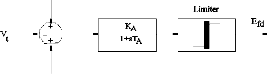
Fig. 1. (a) Excitation system (b) Conventional PSS.
PSS introduces a component of additional damping torque proportional to speed change through the excitation system. The standard IEEE type-1 excitation system is as shown in Fig.1(a). The structure of CPSS is illustrated in Fig
1(b). It consists of an amplification block, a wash out block and a lead/lag block. The lead-lag blocks provide required phase compensation.
Vt
![]()
![]()
q d d d fd
-
Vref +
![]()
![]()
max fd
KA
![]()
![]()
where, 𝑃𝑚 and 𝑃𝑒 are the input and output powers of the
+ 1+sTA Efd min
VS fd
KP
+
+ KI
generator respectively; M and D are the inertia constant and damping coefficient respectively; δ and ω are the rotor
angle and speed respectively; ω𝑏 is the synchronous speed;
′
s
+
sKD
● Δω
𝐸𝑓𝑑 is the field voltage; 𝑇𝑑𝑜 is the open circuit field time
constant; 𝑇 ′ is the open circuit time constant of q-axis; 𝑖
and 𝑖𝑞 are d-axis current and q-axis current respectively; 𝑥𝑑
Fig. 2. IEEE Type-ST1excitation system with PID-PSS
IJSER © 2013 http://www.ijser.org
International Journal of Scientific & Engineering Research, Volume 4, Issue 7, July-2013 1730
ISSN 2229-5518
The structure of PID-PSS along with excitation system is as shown in Fig.2. The input to the PID-PSS controller is
change in rotor speed (∆ω) of the machine on which it is
installed. The system can be described as
• These algorithms work with a population of strings, searching many peaks in parallel, as opposed to a single point.
• Genetic Algorithms work directly on strings of
dE fd
![]()
dt
![]()
= 1 [K TA
A ref
− Vt
+ V )]
(5)
characters representing the parameter set, not the parameter themselves.
• Genetic Algorithms use probabilistic transition rules
where, KA and TA are the gain and time constant of the excitation system respectively; Vref is the reference voltage; KP , KI and KD are the Proportional, Integral and Derivative gain for the machine on which it is installed. The supplementary stabilizing signal Vs is generated with the help of PID-PSS installed in the feedback loop is as shown in Fig.2. The generator terminal voltage is represented by Vt.
instead of deterministic rules.
• Genetic Algorithms use objective function information instead of derivatives or other auxiliary knowledge.
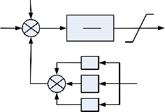
To determine the optimal controller settings, GA method is applied. Genetic Algorithm Optimal Technique is used to minimize performance index which is of Integral Square Error (ISE) type. Speed deviation has been chosen as an error function. Objective function is,
∞
The block diagram of a TCSC with lead-lag compensator is represented in Fig.3 [11]. The reactance XTCSC of a TCSC can be expressed as:
Minimize J e
= ∫ e2 (t )dt
![]()
0
(7)
X TCSC
![]()
= 1 [K Ts
ref
− U TCSC
)− X
TCSC

(6)
where, Xref is the reference reactance of TCSC, 𝐾𝑠 and 𝑇𝑠 are
gain and time constant of TCSC.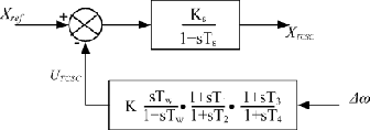
Fig. 3. TCSC with lead-lag controller
Fig. 4. Transfer Function
Here, e(t) is the error signal generated by taking a difference between reference input and the feedback signal. In this study, speed deviation of individual machine is considered as error function.
The linearized system model can be represented by the following equations:
The parameters of CPSS are obtained using phase
∆X
= A∆X + Bu
(8)
compensation techniques and those of proposed PID-PSS
and TCSC based controller are obtained with the help of
Genetic Algorithm, which is discussed in next section.
Genetic Algorithms have recently found extensive applications in solving global optimization searching problems. They are useful when the closed form optimization technique can not be applied. Genetic Algorithms simultaneously evaluates many points in the parameter space, so it is more likely to converge towards global minimum solution.
• Genetic Algorithms are used to search for optimal PID controller parameters. Genetic Algorithms are powerful search algorithms based on the mechanics of natural selection and natural genetics.
Y = C∆X + Du
The eigenvalues λi = σi ± jωdi of the complete system
can be obtained from the linearized relation (8). From the
total eigenvalues of the state matrix A, the eigenvalues corresponding to oscillatory mode can be identified and can be used to get participation factors. In power system
analysis, the participation factor is defined as eri fir where
ei and fi are right and left eigenvectors respectively
corresponding to ith mode. It indicates the effect of r th state
in ith mode. Participation factor is useful as a screen for PSS
placement [16], [17].
The performance of the proposed PID-PSS controller and
TCSC controller and tuning algorithm is tested on a multi-
IJSER © 2013 http://www.ijser.org
International Journal of Scientific & Engineering Research, Volume 4, Issue 7, July-2013 1731
ISSN 2229-5518
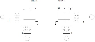
machine system as shown in Fig.5. The adopted system is rather used in small signal stability studies, and it is constituted by two areas interconnected three parallel lines. The system has 4 machines and 10 buses. Each machine is modeled by the fourth order model and is equipped with the first order excitation system and proposed PID-PSS. The
To determine the parameters of PID-PSS of each machine, the optimization problem is formulated as below:
Minimize Je
Subject to
loads shown in the system are modeled as constant
impedance. Detailed data of the system can be obtained from [16].
K min ≤ K K min ≤ K
K min ≤ K
≤ K max
≤ K max
≤ K max
(9)
where Je is the objective function mentioned in (7).
The parameters of PID-PSS are obtained by following an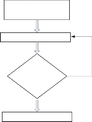
algorithm shown in Fig. 6.
Specify the domain for KP, KI
and KD
Fig. 5. Four machine, 10 bus, two area system
The system exhibits three oscillatory modes with the eigenvalues as mentioned in Table 1.
TABLE 1
EIGENVALUES OF THE SYSTEM CORRESPONDING TO
![]()
OSCILLATORY MODE
Eigenvalues with controllers
![]()
−1.0645 ± j6.487
−0.7547 ± j5.769
−0.3148 ± j3.895
Genetic Algorithm
Number of generation
constraints satisfied? No
Yes
Get KP,KI and KD
![]()
The participation factors corresponding to these modes are shown in Table 2.
TABLE 2
![]()
PARTICIPATION FACTORS
Fig. 6. Flow chart to design PID-PSS based on GA
To set the optimal values of parameters of proposed
PID-PSS, GA has been applied with moderate
population size of 20, number of generation 20, small
λ1 = −0.7547 ±
λ2= −0.7198 ±
λ3= −0.0142 ±
mutation probability of 0.002 and relatively high cross
j6.587 j6.032 j4.049
∆ω1 0.2400-j0.0220 0.0004+j0.0008 0.1607-j0.0125
∆ω2 0.3100-j0.0290 0.0001+j0.0007 0.0990+j0.0003
∆ω3 0.0002+0.0004 0.2464-j0.0310 0.1530+j0.0038![]()
∆ω4 0.0046+j0.0003 0.3149-j0.0139 0.0990-j0.0038
j6.032. PSSs must be kept on these two generators to damp oscillations corresponding to this mode. Participation of all the generators is very small in swing mode (inter-area
mode) with eigenvalue λ3= −0.0142 ± j4.049. So, PSSs kept
on all generators cannot provide adequate damping to this
mode.
over probability 0.8. The solution of (9) gives optimum parameters of the proposed PID-PSS. The optimum value of these parameters for each machine are mentioned in Table 3.
TABLE 3
OPTIMUM PARAMETERS SETTINGS OF PID-PSS
![]()
![]()
The conventional lead-lag PSS (CPSS) is also designed to compare the performance of the PID-PSS for each machine. The parameters of the conventional PSS are obtained by using Phase compensation techniques as explained in [16]. These parameters are given in Table 4.
TABLE 4
IJSER © 2013 http://www.ijser.org
International Journal of Scientific & Engineering Research, Volume 4, Issue 7, July-2013 1732
ISSN 2229-5518
PARAMETERS OF CONVENTIONAL PSS
![]()
T2
![]()
0.04905
0.04607
0.04805
0.04508![]()
The TCSC is included in one of the parallel line (line connecting buses 9 and 10), since such branch is a weak connection which limits the power transfer between the two areas. Besides, the tie-line has a significant influence in the inter-area mode that has to be damped. The difference in the speed between two areas is considered as control signal. The parameters of the TCSC based controller are obtained by solving following optimization problem using GA. In this controller, T w , T 2 and T 4 are usually prespecified [3]. Here, Je is the objective function as mentioned in (7). Minimize Je
Subject to
K min ≤ K ≤ K max
the real part of eigenvalues suggest the effectiveness of the controllers.
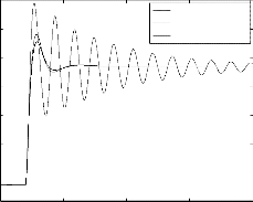
To check the robustness of the controllers, the fault duration is increased to 300 ms. The variation of rotor angle of generator 1 is shown in Fig.8. The performance of the controllers are further verified by applying a step changes of (a) 0.1 pu (b) 0.2 pu in the mechanical input to the generator 1. The changes in the rotor angle of generator 1 are shown in Fig. 9 and Fig. 10 respectively. These result again show that the performance of PID-PSS is better than conventional lead-lag type PSS. However, the incorporation of TCSC has a little effect in the system performance when change in mechanical input is considered.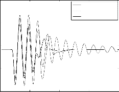
0.6
CPSS
PID-PSS
PID-PSS & TCSC
0.4
0.2
T min ≤ T
≤ T max
(10) 0
1 1 1
T min ≤ T
≤ T max
2 2 2
-0.2
To set the optimal values of parameters of TCSC, GA has
been applied with moderate population size of 50, number
of generation 20, small mutation probability of 0.005 and
relatively high cross over probability 0.4. The optimum
parameters of TCSC based controller are obtained by following the algorithm mentioned in Fig. 6 in which KP , KI and KD are replaced by K, T1 and T3 respectively and they are mentioned in Table 5.
0 5 10 15 20 time (sec)
Fig. 7. Rotor angle of generator-1 for a fault on bus no.10 for 0.2 sec.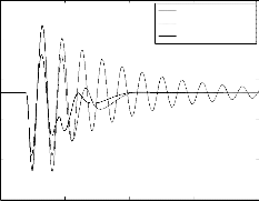
0.4
CPSS
PID-PSS
TABLE 5
OPTIMUM PARAMETER SETTINGS OF TCSC BASED CONTROLLER
0.3
0.2
0.1
PID-PSS & TCSC
The perturbation used to stimulate the oscillation modes in the non-linear simulations is a 200 ms three phase fault at bus 10. In order to observe full transient behavior of the system, sufficiently large simulation time is considered. The variation of rotor angle of generator 1 is as shown in Fig. 7 for aforesaid fault. The simulation result shows that the performance of proposed PID-PSS is better as compared to conventional PSS. Proposed PID-PSS not only reduces the overshoots and undershoots but reduces settling time also. The system comes to steady state condition faster as compared to conventional lead-lag type PSS. The damping of oscillations in the rotor angle is best when proposed PID- PSS and TCSC act together. The eignevalues of the system with controllers are shown in Table 1. The improvement in
0
-0.1
0 5 10 15 20
time (sec)
Fig. 8. Rotor angle of generator -1 for a fault on bus no.10 for 0.3 sec.
IJSER © 2013 http://www.ijser.org
International Journal of Scientific & Engineering Research, Volume 4, Issue 7, July-2013 1733
ISSN 2229-5518
0.2
0.195
0.19
0.185
0.18
0.175
0.17
5
PID-PSS
CPSS
PID-PSS & TCSC
[1] Pouyan Pourbeik, Michael J. Gibbard, “Simultaneous Coordination pf Power System Stabilizers and FACTS Devices Stabilizers in a Multimachine Power System for Enhancing Dynamic Performance”, IEEE Trans on Power Systems, vol. 13, No.2, pp.473-478, May 1998.
[2] Ning Yang, Qinghua, James D. McCalley, “TCSC Controller Design for Damping Interarea Oscillations”, IEEE Trans on Power Systems, vol.13, No 4, pp1304-1310, November 1998.
[3] M.A.Abido, Y.L.Abdel-Magid, “A Hybrid Neuro-Fuzzy Power System Stabilizer for Multimachine Power Systems”, IEEE Trans. Power Systems, vol. 14, no 13, pp1323-1330, November 1998.
[4] Y.L.Abdel-Magid, M.A.Abido, A.H.Mantawy,”Robust Tuning of Power
System Stabilizers in Multimachine Power Systems”, IEEE Trans. on
0.16
0 5 10 15 20
time (sec)
Fig. 9. Rotor angle of generator-1 for a change of 0.1 pu in mechanical input of generator 1.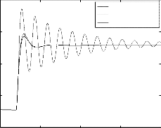
0.185
PID-PSS
CPSS
PID-PSS & TCSC
0.18
0.175
0.17
0.165
0 5 10 15 20
time (sec)
Fig. 10. Rotor angle of generator -1 for a change of 0.2 pu in mechanical input of generator 1
The power system stability enhancement with the help of proposed PID-PSS and TCSC-based controllers is presented and discussed. The Genetic Algorithms was used to find optimal setting of PID-PSS and TCSC-based stabilizers. The proposed stabilizers were tested on a multi-machine power system by applying various disturbances. The simulation results show the robustness and effectiveness of the suggested stabilizers to enhance the system stability. The results are also compared with conventional lag-lead type PSS with change in speed as an input to stabilizer. The simulation results show that the proposed PID-PSS gives better results than a conventional PSS. The use of TCSC- based stabilizer improves the performance of the system further. The TCSC based controller has little effect when sudden change in mechanical input to the generator is considered.
Power Systems, vol.15, No.2, pp 735-740 May 2000.
[5] A.Khodabakhian, R.Hooshmand, R.Sharifian, “Power System Stability Enhancement by Designing PSS and SVC Parameters Coordinately using RCGA”, Canadian Conf. on Electrical and Computer Engineering, pp.579-
582, 2009.
[6] S.M.Bamasak, M.A.Abido, “Damping Improvement of Power System
Oscillation Using STATCOM”, 2nd GCC-IEEE Conf., vol.1, pp 65-71, Nov
2004.
[7] M.A.Abido, Y.L.Abdel-Magid,”Power System Stability Enhancement via Coordinated Design of a PSS and an SVC Based Controller”, 10th IEEE conf. on Electronics, Circuits and Systems, pp. 850-853, 2003.
[8] Li-Jun Cai, Istvan Erlich,”Simultaneous Coordinated Tuning of PSS and FACTS Damping Controllers in Large Power Systems”, IEEE Trans. on Power Systems, vol.20, No.1, pp. 294-299 February 2005.
[9] M.A.Abido, “Design of PSS and STATCOM Based Damping Stabilizers Using Genetic Algorithms”, IEEE Power engineering society general meeting. pp.1-8, 2006.
[10] Nadarajah Mithulananthan, Claudio A. Canizares, John Reeve, Graham J.
Rogers, “Comparison of PSS, SVC and STATCOM controllers for damping power system oscillations”, IEEE Trans. on Power Systems,
vol.18, no.2, pp1-6, May 2003.
[11] A. Beik Khormizi, A. Salem Nia, “Damping of Power System Oscillations in Multi-machine Power Systems using Coordinate Design of PSS and TCSC”, 10th international conference on Environment and Electrical Engg., pp.1-4, 2011.
[12] Roman Kuiava, Ricardo V. de Oliveira, Rodrigo A. Ramos, Newton G.
Bretas,"Simultaneous Coordinated Design of PSS and TCSC Damping
Controller for Power systems" IEEE Power Engineering Society General
Meeting, pp1-6, 2006.
[13] J.M.Ramirez, R.J.Davalos, V.A.Valenzuela,"Coordination of FACTS-Based Stabilizers for Damping Oscillations ", IEEE Power Engineering Review, vol. 20, No. 12, pp. 46-49, Dec. 2000.
[14] Narain G. Hingorani, “Understanding FACTS ”, IEEE Press, 2000.
[15] K .R.Padiyar, “Power System Dynamics, Stability and Control ”, second edition, BS publications, Hyderabad, 2002.
[16] Prabha Kundur,”Power System Stability and Control”, McGraw-Hill Inc., Newyork,1994.
[17] Graham Rogers, “Power System Oscillations ”, Kluwer acadamic publishers, 2000.
Hitesh R. Jariwala is currently working as Associate Professor in Electrical Engineering Department, S.V. National Institute of Technology, Surat, Gujarat, India.
Anandita Chowdhury is currently working as Associate Professor in Electrical Engineering Department, S.V. National Institute of Technology, Surat, Gujarat, India.
IJSER © 2013 http://www.ijser.org
International Journal of Scientific & Engineering Research, Volume 4, Issue 7, July-2013
ISSN 2229-5518
1734