International Journal of Scientific & Engineering Research, Volume 4, Issue 7, July-2013 210
ISSN 2229-5518
Touchpad Controlled Vehicle – a Car in Future
Priyanka Dalvi, Girish Joshi
3208] which gives the co-ordinates of the points touch by the user on touchpad. But in this study Programmable Intercombination Circuit (PIC) [18F4550/18C4550] is used purposefully instead of ADC as input signal were in analog which required converting into digital signal. PIC can be used to interface touchpad and also perform serial port programming far better than ADC. PIC gives output to 8051 microcontroller which uses keil software program in C for input and output programming. Test drive was done to crosscheck the performance of vehicle and it was found that car was moving at correspond given position. Car was moving as directed by touch screen at given location.
—————————— ——————————
n this work, it is aimed to replace not only complicated driv- ing arrangement but also make enable to drive vehicle from inside as well as from outside. The concept of touchpad is acts as a remote of vehicle, which helped it to drive the car
anywhere with and without driver inside it.
Touchpad controlled vehicle has various applications; like this can be use in future as a robot car, as a devise which can be used to identify location of hidden terrorist. Also if a sensor can be placed on it, then it works as movable sensing device to study wild nature thoroughly. Further this can be adopt by putting high quality camera on it and can be use where manu- ally going is not possible.
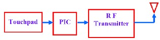
This part consists 4 major blocks as shown in the block dia- gram, given in Fig. 01. The touchpad is interfaced to an ADC (0808 or MCP 3208) which gives the co-ordinates of the point touched by the user on the touchpad. These co-ordinates are fetched by necessary action and transmit a unique character (say 1 for forward, 2 for backward, 3 for left, 4 for left and 5 for stop) serially through serial port. An RF transmitter (315 MHz or 433MHz) is connected to the serial port which transmits these characters through an antenna.
————————————————
• Priyanka Dalvi is completed bachelor of engineering in electronics and
Telecommunication engineering in Mumbai University, India, PH-
+918275634667. E-mail: priyanka.dalvi@vpmmpcoe.org
• Girish Joshi has completed masters degree program in Manufacturing
engineering in Dr. B. A. Technological UniversityLonere, India, PH-
+919765853065. E-mail: girish.joshi@ vpmmpcoe.org
Fig. 1 Block Diagram of Transmitter
In this work, the main signal was in analog form which needs to be converted into digital. For this programmable intercom- bination circuit (PIC) was used instead of analog to digital convertor (ADC). It is advantageous to use programmable intercombination circuit (PIC) over analog to digital convertor (ADC) because PIC can be used to interface touchpad and also perform serial port programming. PIC gives it output to 8051 which uses keil software programmed in C for input, output programming. The output of 8051 is performed on looping basis. The output is transmitted through RF transmitter [1].
This part also consists of 4 major blocks as shown in Fig. 02. The RF receiver receives the serial data (character 1, 2, 3, 4, or
5) transmitted from the remote control circuit and gives it to microcontroller 8051. Depending upon the data received seri- ally 8051 takes move the vehicle, 8051 controls the two 12V DC motors connected to it [2]. The 8051 cannot directly drive the DC motors because it lacks sufficient current. Therefore, a mo- tor driver IC (L293D or ULN2803) is used to drive the motors. The circuit diagram for Vehicle is shown in Fig. 03.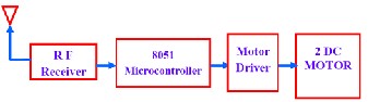
Fig. 2 Block Diagram of Receiver
IJSER © 2013 http://www.ijser.org
International Journal of Scientific & Engineering Research, Volume 4, Issue 7, July-2013 211
ISSN 2229-5518
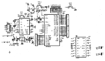
Fig. 3 Circuit Diagram for Vehicle
The transmitted output is received through RF receiver which is connected to another 8051. Here 8051 is used to interface driver and motors. The gist of the project is hidden in this part. The vehicle is operated on the motors which are connect- ed through driver to the 8051. The motion of the vehicle is based on the rotation of the DC motors. The motion of the ve- hicle is as given in Table 01.
TABLE 01
![]()
![]()
MOTION OF VEHICLE ACCORDING TO MOTOR SEQUENCE
Motion | DC motor-1 | DC motor-2 |
FORWARD | FORWARD | FORWARD |
BACKWAED | BACKWAED | BACKWAED |
RIGHT | FORWARD | BACKWAED |
LEFT | BACKWAED | FORWARD |
STOP | NO MOTION | NO MOTION |
![]()
There are four connections of two motors to 8051 microcon- troller. Out of these four connections, two are connected to ground GND and two are connected to VCC supply. For this interfacing any port of 8051 can be used. According to men- tioned combination vehicle moves as per given motion com- mand. Based on this connection various combinations are pos- sible according to which the vehicle is set into motion in par- ticular direction. Interfacing of PIC port with motion of vehicle is given as in Table 02
TABLE 02
INTERFACING OF PIC PORT WITH MOTION OF VEHICLE
A touch screen is a two dimensional sensing device which consist of two sheets of material separated slightly by spacer as shown in Fig. 04. Resistive coating is applied on top film as well as on bottom glass. Polyethylene (PET) acts as a flexible top layer whereas resistive coating on bottom of glass acts as flexible bottom layer. These two sheets are coated with a metal compound called INDIUM TIN OXIDE (ITO) usually. The ITO is thinly and uniformly sputtered onto both; the glass as well as on the PET layer. Tiny bumps called spacer dots are then added to the glass side, on top of the ITO coating, to keep the PET film from sagging, causing an accidental or false touch [3].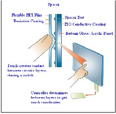
Fig. 4 Typical analog touch screen construction
![]()
When the PET film is press down the two resistive surfaces meet each other. The portion of this meeting can be read by touch screen controller circuit. ‘X’ touch position can be achieved by connecting the controller sets PIN 4 to + 5 V and PIN 2 to the ground (o V). At this condition PIN 1 left uncon- nected. The controller uses PIN 3 to read the voltage where the top layer meets the bottom layer. The controller converts the voltage to a number (data) and sends it to the host computer for further operation. Similarly to get the ‘Y’ touch position the controller sets PIN 1 to + 5 V and PIN 3 grounded. In this case PIN 2 is left unconnected. For capturing ‘Y’ touch position the controller uses PIN 3 to read the voltage where the top layer meets the bottom layer. Again, the controller converts the voltage to a number (data) and sends it to the host computer [4]. The capturing of ‘X’ and ‘Y’ is as shown n Fig. 05.![]()
MOTION | PORT 1 | PORT 2 | PORT 3 | PORT 4 |
FORWARD | 1 | 0 | 1 | 0 |
BACKWARD | 0 | 1 | 0 | 1 |
LEFT | 1 | 0 | 0 | 1 |
RIGHT | 0 | 1 | 1 | 0 |
STOP | 0 | 0 | 0 | 0 |
![]()
IJSER © 2013 http://www.ijser.org
International Journal of Scientific & Engineering Research, Volume 4, Issue 7, July-2013 212
ISSN 2229-5518
and also it is compact in size. L293D is a monolithic integrated high voltage, high current for channel driver which designed to accept standard DTL or TTL logic levels and drive loads. The L293D is assembled in a 16 lead plastic has four centre pins connected together and used for heat sinking [5].
Fig. 5 Capturing (a) “X” Touch, (b) “Y” Touch
In fact a PIC microcontroller is an amazingly fully featured processor with internal RAM, EEROM FLASH memory and peripherals. One of the smallest ones occupies the space of a
555 timer but has a ten bit ADC, 1K of memory, two timers; high current input output ports a comparator a watch dog timer. One of the most useful features of a PIC microcontroller is, it is re- programmable as it uses flash memory. ICSP serial interface built also use into each PIC microcontroller for pro- gramming. PIC microcontroller can be programmed by using assembler or a high level language and it is recommend using high level language such as C as it is much easier to use. Flash memory is the program storage area and gives the most im- portant benefit for using PIC microcontroller. Device used in this research was re-programmed up to 100,000 times as it uses flash memory. Circuit diagram of PIC used in this work is given in Fig. 06.
Fig. 6 Circuit Diagram of PIC
DC motors are operated on 12 V supply. Microcontroller 8051 is not capable of providing such a high voltage. It require mo- tor driver to overcome this problem. There are three drivers available –ULN2803, L298 and L293D. In this study L293D driver is used because it is cost effective as compare to other
Voltage regulator produces fixed DC output voltage from var- iable DC (a small amount of AC in it). Normally fixed output is getting by connecting the voltage regulator at the output of the filtered DC as shown in Fig. 07. It can also used in circuit to get low DC voltage from high DC voltage. In this work 7805 voltage regulator is used to get supply of 5 V from 12 V. 78XX is most commonly used series of voltage regulator, but in this research 7805 voltage regulator is used because it gives fixed 5
V DC voltage for input voltage range of 7.5 V to 20 V.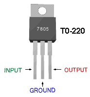
Fig. 7 Voltage Regulator
The MAX232 family of line driver or receiver is intended for all EIA/TIA 232E and V.28/V.24 communication interface. These parts especially useful in battery power system, since its low power shutdown mode reduces power dissipation to less than 5V. MAX 232 needs external capacitors for the internal voltage pump.
In the present vehicle, TX4915-F transmitter is used for modu- lation. The TX4915-F is an entire Phase-Locked Loop (PLL) for precise local Oscillator generation. It can use in OOK / HCS / PWM signal and modulate to transmit signal to receiver de- vice by air .It had a high performance and easily to design your product. In present study, RF transmitter TX4915 is used for specific remote-control function. It supports
315MHz/433.92MHz/868.35MHz/914.5MHz for ISM Band modules.
In receiver section of this vehicle, the RX3400 is a Miniature receiver module that receives FSK Modulation Signal and de- modulated to digital signal for the next decoder stage. Local Oscillator is made of PLL structure. Since RX3400 is designed specifically for remote-control and wireless security receiver operating at 315MHz/433.92MHz, in this research it is used in
IJSER © 2013 http://www.ijser.org
International Journal of Scientific & Engineering Research, Volume 4, Issue 7, July-2013 213
ISSN 2229-5518
remote control section. The circuit diagram for RF transmit- ter/RF receiver used in this work is as shown in Fig. 08.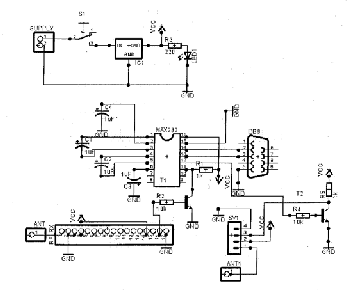
Fig. 8 Circuit diagram of RF Transmitter/RF Receiver
In the present study touch screen is interfaced with Program- mable Intercombination Circuit (PIC 18F4550). Figure 09 shows touch screen interfacing with PIC. It indicates touch screen having four channels interfaced with PIC PIN. Out of these four channels, channels 1 and 2 are digital pins whereas channel 3 and 4 are analog pins. Pins RB0, RB1, RB2, and RB3 are connected to channel 1, 2, 3 and 4 respectively. Pin RB2 and RB3 which are nothing but AN8 and AN9 (analog pin) are interfaced with channel 3, 4 to take analog input from touch screen [6,7].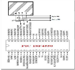
Fig. 9 Touch screen interfacing with PIC 18F4550
This interfacing configuration of port B is explained in follow- ing Table No. 03.This provides information regarding three
major modes which are touch detection, X channel detection and Y channel detection. When PIN 3 and 4 are constant and PIN 2 is connected to digital input of PIC then it started sens- ing of touch detection. Similarly, PIN 3 is connected to AN8 and PIN 4 is connected to + 5 V then it detects X channel whereas PIN 1 is connected to + 5 V and PIN 4 is connected to AN9 then it detects Y channel [8].
TABLE NO. 03
PORT B CONFIGURATION
Function | RB0 PIN 1 Touch Screen | RB1 PIN 2 Touch Screen | RB2 PIN 3 Touch Screen | RB3 PIN 4 Touch Screen |
Touch Detection | 0 | Digital input | NC | NC |
X_ Channel | NC | 0 | AN 8 | + 5 V |
Y_ Channel | + 5 V | NC | 0 | AN 9 |
The touch detection is schematically represented as given Figure
10.
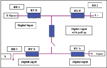
Fig. 10 Touch Detection
In this study, Keil software is used for touch screen program- ming. The Keil software is C compiler software. It converts C language into the machine language. The program which exe- cutes motion of touch pad controlled vehicle is as given below. Program consist five different positions of vehicle; those are left, right, forward (top), backwards (bottom) and center. In this program entire touch screen is divided into X mode and Y mode. These two modes decide different positions of vehicle and on the basis of these positions program is made through which vehicle gets appropriate motion.
IJSER © 2013 http://www.ijser.org
International Journal of Scientific & Engineering Research, Volume 4, Issue 7, July-2013 214
ISSN 2229-5518
# include<p18f4559.h>
#include”delay.h”
#include”ADC.h”
#define DEBUG
#define to Ascii(x)(x+0x30)
#define X_MAX 860
#define Y_MAX 910
#define X_MIN 72
#define Y_MAX 55
#define X_MID X_MAX/2
#define Y_MID Y_MAX/2
#define BOX_LENGTH 200
#define LEN BOX_LENGTH/2
#define SEPARATOR 100
#define CENTER_BOTTOM_LEFT_X X_MID-LEN
#define CENTER_BOTTOM_LEFT_Y Y_MID-LEN
#define CENTER_BOTTOM_RIGHT_X X_MID+LEN
#define CENTER_BOTTOM_RIGHT_X Y_MID-LEN
#define CENTER_TOP_LEFT_X X_MID-LEN
#define CENTER_TOP_LEFT_Y Y_MID+LEN
#define CENTER_TOP_RIGHT_X X_MID+LEN
#define CENTER_YOP_RIGHT_Y Y_MID+LEN
#define RIGHT_BOTTOM_LEFT_X X_MIN (LEN+SEPARATOR+BOX_LENGTH)
#define RIGHT_BOTTOM_LEFT_Y Y_MID-LEN
#define RIGHT_BOTTOM_RIGHT_X X_MID(LEN+SEPARATOR)
#define RIGHT_BOTTOM_LEFT_Y Y_MID-LEN
#define RIGHT_TOP_LEFT_X X_MIN
#define RIGHT_TOP_LEFT_Y Y_MID+LEN
##define RIGHT_TOP_RIGHT_X Y_MID- (LEN+SEPARATOR)
define RIGHT_TOP_RIGHT_Y Y_MID+LEN
#define LEFT_BOTTOM_LEFT_X X_MID
+LEN+SEPARATOR
#define LEFT_BOTTOM_LEFT_Y Y_MID-LEN
#define LEFT_BOTTOM_RIGHT_X X_MAX (LEN+SEPARATOR+BOX_LENGTH)
#define LEFT_BOTTOM_RIGHT_Y Y_MID-LEN
#define LEFT_TOP_LEFT_X X_MID+LEN+SEPARATOR
#define LEFT_TOP_LEFT_Y Y_MID+LEN
#define LEFT_TOP_RIGHT_X X_MAX (SEPARATOR+BOX_LENGTH)
#define LEFT_TOP_RIGHT_Y Y_MID+LEN
#define TOP_BOTTOM_LEFT_X X_MID-LEN
#define TOP_BOTTOM_LEFT_Y Y_MID+LEN+SEPARATOR
#define TOP_BOTTOM_RIGHT_X X_MID+LEN
#define TOP_BOTTOM_ RIGHT _Y Y_MID+LEN+SEPARATOR
#define TOP_TOP_LEFT_X X_MID-LEN
#define TOP_TOP_LEFT_Y Y_MAX
#define TOP_TOP_RIGHT_X X_MID+LEN
#define TOP_TOP_RIGHT_Y Y_MAX
#define BOTTOM_BOTTOM_LEFT_X X_MID-LEN
#define BOTTOM_BOTTOM_LEFT_Y Y_MIN (LEN+SEPARATOR++BOX_LENGTH)
#define BOTTOM_BOTTOM_RIGHT_X X_MID+LEN
#define BOTTOM_BOTTOM_RIGHT_Y Y_MIN
#define BOTTOM_TOP_LEFT_X X_MID-LEN
#define BOTTOM_TOP_LEFT_Y Y_MID- (LEN+SEPARATOR)
#define BOTTOM_TOP_RIGHT_X X_MID+LEN
#define BOTTOM_TOP_RIGHT_Y Y_MID- (LEN+SEPARATOR)
#define DELTA_X 75
#define DELTA_Y 75
#define DEFAULT 0
#define NOT_DEFAULT 1
#define TOUCH_DETECTED 1
#define TOUCH_NOT_DETECTED 0
Void main ()
{ //initialize serial communication
Serial_init();
// initialize ADC
ADC_init(); //init ADC peripheral
Delay 10KTCYx (255);
While (1)//; //loop forever
{
//TOUCH DETECT Configure_TouchDetect();
While(TouchDetect()!=TOUCH_DETECTED);
//configure for RB2,RB3 as analog input
Configure_ADC();
//X Channel
Configure_X_Channel();
// wait for screen to initialize Delay10KTCYx (1); Select_Channel(Channel8); Start_Conversion(); ConversionVGGGGVGGGGGGGBGVJJ While (ADCOV0bits.GO);
//read x channel reading’ADC_Result=Read_ADC_Result(); X_Cord=ADC_Result;
//Delay between conversions.
//it is a library function, refer deley.hfile in MCC18 installa- tion directory
Delay10KTCYx (255);
//Y Channel
Configure_Y_Channel();
//wait for screen to initialize
Delay 10KTCYx (1);
Select Channel (Channel9); Start Conversion ();
While (ADCON0bit.GO);
IJSER © 2013 http://www.ijser.org
International Journal of Scientific & Engineering Research, Volume 4, Issue 7, July-2013 215
ISSN 2229-5518
//Read y channel reading ADC_Result=Read_ADC_Result (); Y_Cord=ADC_Result;
//finds screen position left,right,top,right or center
Find_Screnposition ();
}
}
In this current study, performance of vehicle is evaluated by tak- ing number of test drives. It is found that vehicle reaches to ap- propriate position as per instructed by touchpad. Followings are major conclusions.
• Moving capacity of this vehicle is totally dependent of ca- pacity of RF transmitter and Receiver. In the present study it was found to be 12 – 16 meters. High quality, high capacity RF transmitter and Receiver provide more moving area.
• Programmable Intercombination Controller PIC 18F4550 is found to be suitable for this application because it inbuilt programmable flash memory.
• It is observed that L293 D motor driver is effectual as it works even for least power supply of +5 V to drive vehicle.
• This present model can be used for wild life discover just by attaching micro-camera on it for example to study living style of snake, tiger etc. This can be also used in critical situ- ations like identifying exact location of hidden terrorist, en- emy.
• It can be used where reaching of human being is practically not possible and fulfill all required activity just by adding appropriate high quality sensors on it.
The authors gratefully acknowledge the great support from SSPM college of Engineering, Kankavli, Sindhudurg. Also, the authors would like to thank to the Mumbai University for support.
[1] Brian W. Grasby, “A smarter computer controlled model car”, Monash
University School of Computer Science and Software Engineering, 2002. [2] Johansson, H. & Walter, K. “InVehicle Screen-Density, Driver distraction
and User Preferences for Low vs. High Screen Density in intergrated
Display”, Linkoping’s Universitet, Sweden, 2005.
[3] Landauer, T. K., Nachbar, D. W. “Selection from Alphabetic end Numeric Menu Treea Using A Touch Screen: Breadth, Depth, and Width”, Bell Communications Research Morristown, N.J. 1985.
[4] Vilimek, R., Zimmer, A. (2007) “Development and Evaluation of a Multimodal Touchpad for Advanced In-Vehicle Systems”, Engin. Psychol. and Cog. Ergonomics, HCII 2007, Springer- Verlag Berlin Heidelberg.
[5] Jamson, A.H. & Merat, N. “Surrogate in-vehicle information systems and driver behaviour: Effects of visual and cognitive load in simulated driving”, Transportation Research F, 8 (2). pp. 79-96. ISSN 1369-8478, 2005.
[6] Rydström, A., Broström, R. & Bengtsson, P. (2008) “Safety aspects of using multifunctional control interfaces while driving – a simulator”, 2007
[7] Gary Burnett, Glyn Lawson, Laura Millen, Carl Pickering “Designing touchpad user-interfaces for vehicles: which tasks are most suitable” Jaguar and Land Rover Technical Research, Jaguar Cars Ltd, Whitley, Coventry, UK,2007.
[8] Stefan Norberg and Professor Ulrike Rahe, “Touchpad as interaction input
control for use of in-vehicle infotainment systems”, Chalmers University of
Technology, Division Design Department for Product and Production, 2007
IJSER © 2013 http://www.ijser.org