International Journal of Scientific & Engineering Research, Volume 3, Issue 10, October-2012 1
ISSN 2229-5518
Tooth-Bending Effects in Plastic Spur Gears
Influence on load sharing, stresses and wear
Asst.Prof.Subburaj Ramasamy
Index Terms— Consequences, FEA, Gear teeth, Kinematics, Load sharing, PV Pressure Velocity, Stresses.
—————————— ——————————
LASTIC gears are now commonly used in the more de- manding automotive applications, such as electronic pow- er steering, electronic throttle control and starter motors.
However, the fundamental knowledge of plastic gear design and engineering does not seem to have kept pace with the number of gear applications.
Much research was done in the 1970s and 1980s, especial- ly in Germany, on predominantly polyacetal (POM) and pol- yamide (PA) gears (Refs. 1–8). These experimental investiga- tions focused on measuring the load capabilities for various gears under varying conditions. These studies typically yielded curves for the normalized force versus the number of cycles to failure. In this approach, the module of the gear and other geometry factors are still important variables. Relative- ly little attention was paid to stress analysis and wear mech- anisms and how these changed under varying conditions. The standardized calculations of ISO 6336 and DIN 3990 were used to calculate indicative stresses, but it was under- stood that a lot of discrepancies existed between “metal” theories and “plastic” practice. In the 1980s, a specific plastic gear standard was developed by VDI (VDI 2545), and although it was withdrawn again in 1996 for unknown reasons (Ref. 9), this standard is still commonly used. In the 1980s, Yelle and Burns (Ref.10) conducted substantial research to develop a more fundamental base to plastic gearing. Their approach succeeded in accounting for the tooth bending of plastic gears and in calculating real contact ratios for this type of transmis- sion.
————————————————
Professor.Subburaj Ramasamy.R is currently working as Assistant professor in Mechanical Engineering Departmant in Sakthi Marriamman Engineering College.
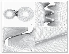
Figure 1—Details of the FE mesh. An overview of the complete model is shown in figure a, while zooming in on the refined mesh in the contact area from figures b to d.
With the ongoing development of finite element software packages and improved algorithms accompanied by sufficient computing power in the 1990s it became possible to solve complex contact problems like meshing (plastic) gears.In the group of Walton at the University of Birmingham, the experi- mental research on plastic gears was combined with numerical work (Refs.11 and 15–17). They confirmed the analytical find- ings of Yelle and Burns by FEA and showed that load sharing changes dramatically for plastic gears. Kapelevich and co- workers used FEA to modify tooth shapes and to optimize the tooth geometry specific for plastic gears (Ref. 14).
However, although substantial research has been conduct- ed in the field of plastic gears, this does not seem to have re- sulted in generally accepted design rules. Today’s plastic gear designs still seem to be based on empirics, experience and comparative calculations based on metal gear standards.
IJSER © 2012
International Journal of Scientific & Engineering Research, Volume 3, Issue 10, October-2012 2
ISSN 2229-5518
The essential differences between metal and plastic gears and how they affect kinematics, stresses and wear issues—are still rather undefined
In building knowledge in the field of plastic gearing, many
fundamental questions were encountered. For instance, what are the differences in kinematics between plastic gears and metal gears? To what extent are the standards developed in the
1970s for metal gears applicable for plastics?
To find answers to these questions, a program to compare the results of semi-analytical methods (e.g., ISO standards and KissSoft) and finite element analysis was begun, in addition to an extensive experimental program on plastic gears. In our approach, these calculations were used to study previously observed phenomena, like changes in contact path length and load sharing, but also to investigate stresses and kinematics. Finally, a hypothesis was formulated on the governing mecha- nism of wear in plastic gears.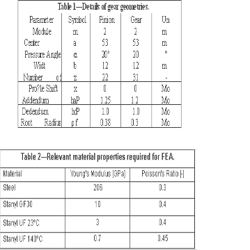
This paper describes the results of Finite Element Analyses (FEA) per- formed in order to study the effect of modulus and tooth bending on the kinematics and stresses in a gear pair. The FEA were done using a commercial FE software package, MSC.MARC. The gears were modeled as two discs with four teeth each, under plane strain conditions (2-D analysis). Around 80,000 first-order quads were used, with a refined mesh near the contact surfaces, in order to capture accurately the con- tact stresses. Detailed pictures of the finite element mesh of the gears are shown in Figure 1.
Linear elastic deformation behavior was assumed for all materials. Although the unfilled materials do show signifi- cantly inelastic behavior, this is expected to have only a mi- nor influence.
The calculations were done using the ISO 6336 standard
(similar to DIN3990) and KissSoft machine design program
(semi-analytical).
In this study the focus was on a gear transmission, con- sisting of a steel pinion and gear, which was made of various materials. Both gears have a module of two, a width of 12 mm, and no profile shifts are applied. The tooth profile is standard according to DIN 867, with a pressure angle of 20°. Further details are given in Table 1.
In the FEA, different material properties were assigned to
the gears. A steel gear was chosen, with the same properties as the pinion, a glass- fiber (GF)-reinforced grade of Stanyl (PA-46, 30 wt % glass fiber), and an unfilled Stanyl, tested at either room temperature or at 140°C. The relevant elastic properties are given in Table 2.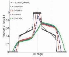
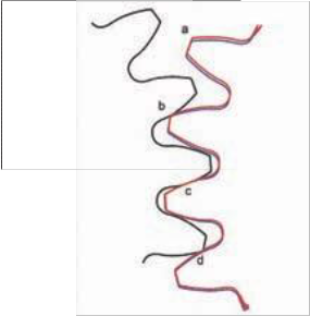
Figure 2—Load sharing between teeth of a steel pinion and a steel gear (black circles), a glass fiber (GF)-reinforced plastic gear (red circles), an unfilled plastic gear (blue circles) and an unfilled gear at elevated temperature (green circles). The dashed black line represents the theory (ISO 6336) and the dotted black line indicates the pitch point.
Figure 3—Tooth bending due to the combination of high load/low stiffness. The black lines represent the pinion, the blue line a steel gear, and the red line a plastic gear.
IJSER © 2012
International Journal of Scientific & Engineering Research, Volume 3, Issue 10, October-2012 3
ISSN 2229-5518
3/3rule, meaning that the load fraction at the initial moment of contact equals 1/3, increases to 2/3 at the moment the preced- ing tooth is leaving the contact, and is carrying the full load during the period of single-tooth contact around the pitch point. After the pitch point, the load fraction follows the same scheme, but in reverse order. In Figure 2, which shows the load fraction as a function of the roll angle (rotational angle of the pinion), this is represented by the dashed (theoretical) line.
Using FEA, the load sharing can also be studied. Calcula- tions and other studies in literature (Refs. 11 and 12) show that during meshing of two steel gears, load sharing is closer to a
2/5-3/5-5/5 rule, represented in Figure 2 by the black circles
(E=206 GPa).
When a steel pinion meshes with a plastic gear, the load sharing changes dramatically. Figure 2 shows the load sharing for combinations of steel and various plastics, and the most striking change is that the load sharing becomes skewed when a steel pinion meshes with a plastic gear, resulting in a load share of approximately 1/3 in the first part of the meshing cycle and a load share of 2/3 in the last part.
Another significant effect is that the contact path increases, resulting in a preliminary contact earlier in the meshing cycle and a prolonged contact at the end, reducing the period of single- tooth contact. This has already been reported in litera- ture in analytical (Ref.10) and numerical studies (Refs. 11 and
12). For a glass fiber-reinforced plastic gear (E=10 GPa), repre-
sented by the red circles in Figure 2, the single-tooth contact period is approximately halved, compared to a steel-on-steel combination. For an unfilled plastic gear (E=3GPa) and an unfilled plastic gear at elevated temperature (E=0.7 GPa), re- spectively, represented by the blue and green circles, single- tooth contact no longer occurs during meshing. With decreas- ing modulus, the maximum load share decreases to a plateau value of approximately 2/3. The origin of these effects lies in the fact that considerable tooth bending takes place, as is shown in figure 3.
The black steel pinion meshes with the blue steel gear, as expected, while considerable tooth bending for the red plastic gear is observed. At position ‘a,’ the red gear has a significant lag compared to the blue gear. At position ‘b,’ a lag can still be seen in that the red gear comes into contact with the black pin- ion before the theoretical point of initial contact. For position
‘c,’ the teeth of the red and blue gear are virtually at the same position. However, this tooth is the most deformed, making the rest of the gear and teeth lag. At position ‘d,’ the load on the tooth reduces and the tooth bends back.
Tooth bending is not solely determined by the modulus of
the gear, but also by a combination of stiffness (Young’s mod- ulus) and loading. As the ratio of Young’s modulus and yield stress (i.e., loading limit) for polymers is roughly an order of magnitude lower than for steel, tooth bending plays a much more prominent role in plastic gearing.
place during meshing of plastic gears, resulting in an extended contact path. In theory, the contact path length is defined as the length along the contact line from the initial point of con- tact until the last point of contact divided by the base circle pitch.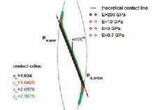
Figure 4—Contact path during meshing of a steel pinion with a gear of various materials.
As can be seen in Figure 4, the theoretical line of contact— typical for involute gearing—is well captured by two meshing steel gears (black circles). A contact ratio, of 1.634, derived by FEA, also agrees well with theory (1.63). For a GF-reinforced
plastic (red circles), the contact ratio increases to 1.84, and for
IJSER © 2012
International Journal of Scientific & Engineering Research, Volume 3, Issue 10, October-2012 4
ISSN 2229-5518
an unfilled plastic, a contact ratio of two is just exceeded, which corresponds well with the fact that single-tooth contact was not seen in Figure 2. For an unfilled plastic gear at elevat- ed temperature, the contact ratio goes to 2.37.
As can be seen in Figure 4, for plastic gears the contact
path increases at the beginning and end. However, the exten- sion of the contact path does not coincide with the straight con- tact line, but instead bends off. In fact, the extension of the con- tact path lies exactly on two circles—the tip circles of both gears.
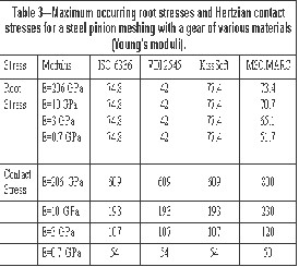
Furthermore, Table 3 shows that both the root stresses and the Hertzian contact stresses decrease with decreasing Young’s modulus of the mating gear. For the Hertzian con- tact stresses, this perfectly agrees with theory, as the contact stresses are dependent on the contact stiffness. For the root stresses, this is less evident, as the stress level in theory only depends on geometry and load. Nevertheless a decrease is seen for plastic gears, which is the subject of further investi- gation in the next sections.
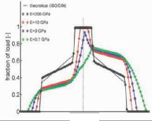
Figure 5—Root stress as a function of the roll angle for a steel pinion meshing with gears of various materials (moduli).
For a steel pinion and gear, the root stress is around 45
MPa in the first part of the meshing cycle. At the first moment
of single-tooth contact, a jump to 74 MPa is seen. With increas- ing roll angle, the stress level lowers again as the contact point moves down along the tooth flank of the gear, reducing the lever arm. At the end of single-tooth contact, a large decrease is seen—to some 35 MPa—reducing even further towards the end of the meshing cycle.
As the load fraction carried by a single tooth deter- mines the level of the root stress, the fact that the load sharing becomes skewed for plastic gears is expressed in the root stresses. The root stresses are considerably lower in the first stage of the meshing cycle compared to steel gears, and are considerably higher at the last part of the meshing cycle. De- pending on the con- tact ratio and thus modulus, a period of single-tooth contact is achieved during which the root stresses become high. As can be seen in Figure 5, the level of root stresses reached in the single- tooth contact period follows the same trend as those found in steel gears.
However, due to the changes in load sharing, the time span of single-tooth contact becomes shorter, and the high stress level of the initial moment of contact for a steel gear is not reached. For an unfilled plastic gear at elevated tempera- ture, the peak stresses around the pitch have completely dis- appeared, and the maximum values tend to go to a value of some 2/3 of the theoretical maximum value. It is expected that a further decrease of the modulus will not result in a further decrease of the root stress level.
An implication of this lowered root stress (compared to standardized calculations) is that the gears can be loaded to higher torques than expected based on the comparison of the theoretical root stress and yield stress of the material. This does not mean that the standardized approach is fundamental- ly wrong, but rather that it should be modified by incorporat- ing the altered load sharing due to tooth bending.
ing meshing of two gear teeth can be estimated using Hertzian theory. The contact stresses can be expressed as a function of the load, contact stiffness, reduced radius of the contact and the width of the contact, according to:
where F is the force (load), Er reduced modulus or contact stifness (see equ 2), b is the width of the gear and Rr is the reduced radius of the contact (see equ 3)
Where Eg & Rp are the young’s modulus, Vg & Vp are the pois-
son’s ratios of the gear and pinion, respectively,
IJSER © 2012
International Journal of Scientific & Engineering Research, Volume 3, Issue 10, October-2012 5
ISSN 2229-5518
Where Rg & Rp are the local radii of the tooth flanks of the gear and pinion, respectively.
The FEA results of the contact stresses as a function of the roll angle are represented in Figure 6. The contact stresses for a steel pinion and gear, rep- resented by black circles, have a maxi- mum in the region of single-tooth con- tact (around 800
MPa). This agrees with the values that were calculated semi-
analytically. Furthermore, the local radii of curvature and the load fraction deter- mined the course of the contact stress, as a function of roll angle.
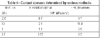
According to Equations 1 and 2, the maximum contact stress occurring around the pitch point will reduce markedly with decreasing modulus. For a GF-reinforced plastic gear, the maxi- mum contact stress around the pitch point reduces from 800 MPa to 250 MPa. For an unfilled plastic gear, this reduces to 120 MPa, and at elevated temperature to 50 MPa. The values found using FEA correlate very well with the val- ues using standardized calculations or KissSoft (Table 4).
However, as can be clearly seen in Figure 6, very high
peaks appear at the beginning and end of the meshing cycle. Due to the tooth bending and the increased contact path, pre- liminary and prolonged contact occurs for plastic gears. At preliminary contact, the tip of the gear meshes with the root of the pinion, while at the prolonged contact, the tip of the steel pinion meshes with the root of the gear. This implies that it is not the involute parts of the flanks that are meshing, but that the tip of the tooth, which is determined by tip radius (tip ra- dius equals 0.1 mm in the calculations), is in contact with the other tooth flank. For a GF-reinforced plastic gear (red circles), the contact of the sharp tip radius of the steel pinion and the tooth root of the gear (end of mesh- ing cycle) results in a con- tact stress of 940 MPa, which exceeds the values found for the steel pinion and gear. For an unfilled plastic gear, the value of the contact stress reaches 500 MPa at room temperature and
220 MPa at elevated temperature.
Using Equation 1 and taking the load sharing into ac- count, the contact stress at the prolonged contact can be esti- mated using Equation 4.
![]() (4)
(4)
Where αls the load sharing factor and Rtip is the tip radius. Figure 2 shows that the load share carried by a single tooth at the moment the maximum contact is observed is around 50% and hence αls is chosen to be equal to 0.5.The maximum values found by FEA and those obtained using Equation 4 compare very well (Table 4, Column 3). This equation can be used to estimate contact stresses, based on geometry and loading, without going through the elaborate process of FEA.
20%), PV values are found which are much higher than calcu-
lated based on conventional theory.
Figure 7 shows the PVvalues for a steel pinion meshing with a gear of various materials. For a GF-reinforced gear, the PV value is expected to drop by a factor of 4; instead, a value is found which exceeds the PV value of a steel-on-steel combina- tion by 30%. For the unfilled materials, the PV values are about a factor of seven times higher than those calculated by conven- tional theory. The PV values calculated by conventional theory and FEA are summarized in Table 5.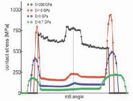
Figure 6—(Hertzian) contact stress as a function of the roll angle for a steel pinion meshing with a gear of various materials.
It must be noted that the calculations are performed using a tip-rounding radius of 0.1mm. If a larger tip radius is used, contact stresses will drop according to equation 3. In a steel- plastic combination, the peak in contact streeses and PV value at the beginning of the meshing cycle is less important than the peaks at the end. At the beginning of the meshing cycle, the tip of the poastic gear is in contact with the root of the steel gear.
After running in, the tip of the plastic gear will be worn in
IJSER © 2012
International Journal of Scientific & Engineering Research, Volume 3, Issue 10, October-2012 6
ISSN 2229-5518
such a way that its contact radius has become larger and the contact stresses have reduced. Apart from a lowered contact ratio, this will have no significant negative side effects.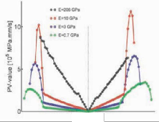
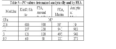
Figure 7—PV values found for a steel pinion meshing with gears of various materials.
A closer look at Figure 4 reveals that the extension of
the contact path is perpendicular to the contact line and the rest of the contact path. Combined with the bending of the teeth, the question arises whether the involute flanks are still meshing properly. Therefore the kinematics of the meshing teeth were investigated in more detail. Figure8 shows four subsequent images of the gear flank on four stages during the meshing cycle.
Figure 8a shows that, at the initial contact stage, the tip of the gear flank is in contact with the root of the pinion. Although not visible in this picture, the tip (and thus tip rounding) re- main in contact for quite awhile, meaning that the rolling component of the velocity is very low during this stage. Therefore this stage can be regarded as if a plastic pin (or cylinder) is sliding on a steel surface.
With increasing roll angle, the con- tact point slides along the flank, as is expected based on theory. The involute flanks mesh properly and the contact point moves with fluid motion from the tip to the root of the gear (Fig. 8b).
Figure 8c visualizes the last moment of the meshing cycle
when the contact point has moved along the contact line and reached the root of the gear. The contact point then enters the stage of prolonged contact.
Figure 8d reveals what is actually happening in the exten- sion of the contact path the contact point is moving back along the flank towards the pitch point. Hence in the pro- longed and also preliminary contact, a reciprocating move- ment takes place at the root of the gear with a high sliding velocity, and very high contact pressure (and high PV).
In the case of a steel pinion meshing with a plastic gear, it is as if a sharp cylindrical, steel tip (radius of curvature equals the tip-rounding radius) is digging into the root of the gear. Depending on the length of the contact path (and thus tooth bending and Young’s modulus), the end of contact ap- proaches the pitch point.
Our hypothesis now is that this high-PV, reciprocating movement at the beginning and end of the contact is the gov- erning mechanism of wear in plastic gears.
To substantiate this hypothesis, the results of experi-
mental studies were consulted. The first results investigated are experimental studies conducted by Walton and Weale at the University of Birmingham, in which they performed ex- periments on polyacetal (POM) gears to investigate their wear behavior (Ref.17). Although our simulations are done on steel-plastic combinations, the same phenomena will oc- cur in plastic gear pairs.
At the tooth tip, indicated by ‘a’ in Figure 9, high wear is
observed. This can be explained by the fact that the tip of the gear is coming into preliminary contact with the root of the pinion, experiencing a high PV (Fig. 7; i.e., negative roll angles, left-hand side).
T h e addend u m s h o w s a much smoother wear pattern,
indicated by ‘b’ in Figure 9. In light of the simulations, in which the involute tooth flanks of the addendum are meshing properly (although still at a considerable PV), this is also in agreement.
In the region indicated by ‘d,’ the most severe wear oc-
curs, and the surface shows surface pits and scoops. This is the region in which the high PV, reciprocating movement takes place, and indeed the most severe wear is expected in this area.
The last striking feature is the formation of a ridge near the pitch point. This can be explained by the fact that, due to the reciprocating movement, the tip of the pinion returns at a high PV towards the pitch point. The high contact pressure digs out and deforms material, and pushes it toward the pitch
point. At the end of the meshing cycle the pressure reduces,
IJSER © 2012
International Journal of Scientific & Engineering Research, Volume 3, Issue 10, October-2012 7
ISSN 2229-5518
leaving the deformed material on a ridge. The severe effects seen in Figure 9 are the result of many repeated cycles.
If the mechanism described above is the governing mech- anism in the wear of plastic gears, it would imply that the wear scars on the pinion (driver gear) and driven gear must be dif- ferent. The reason for this is that, for the driven gear, the con- tact point moves from the tip to the root and then moves back towards the pitch point, as shown in Figure 8. For the drive gear, the opposite is true; the tip of the gear contacts the pinion near the pitch point and moves towards the root of the pinion, pushing the material down. The direction of the movement changes, and the contact point moves along the contact line from the root to the tip of the pin-ion. The experimental study on polyacetal gears (Ref. 17) shows that the wear patterns at the dedendum of the pinion (drive gear) are very different and that a valley or depression without ridges is seen near the pitch point.
Breeds, et al., (Ref. 17) explained the observed differences
by the fact that the surface stresses resulting from the friction forces are compressive for the driven gear, while the driver gear experiences tensile stresses. The differences in wear of the addendum and dedendum were explained by the fact that the directions of the rolling and sliding velocities are different above and below the pitch point. Thus the rolling component of the tip of the gears in the preliminary and prolonged contact is only of minor influence.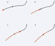
Figure 8—Kinematics of two meshing tooth flanks (only gear flank is drawn). The solid black line represents the tooth flank of the gear, the black dot represents the pitch point, the red dot rep- resents the moving contact point and the solid red line represents the part of the flank that has already been in contact.
Further support for our hypothesis is found in an ex- perimental study of White, et al. (Ref. 18), in which they inves- tigated the effect of tip relief on wear in plastic spur gears. Their general observation is that tip relief has very beneficial effects on the wear performance of plastic gears and that dou- bling the amount of required tip relief (based on calculations) gives the lowest wear rates. They state further that the shape of tip relief is important, as it determines the level of contact stress. These observations complement our simulations, as tip
relief reduces the effects of preliminary and prolonged contact. Moreover, the level of contact stress can also be considerably lowered. For example, applying a tip rounding radius of 0.3 mm instead of 0.1 mm reduces the PV value by 30%.
It has been shown that the load sharing of a steel- plastic gear pair changes dramatically compared to the con- ventional theory of steel gears. Not only does the length of the contact path increase, so also does the shape of load sharing change due to significant tooth bending. For steel-to-steel and plastic-to-plastic gear pairs, the load sharing is symmetrical around the pitch, while for a steel-plastic gear pair it becomes skewed, and the teeth face the most severe loading in the last part of the meshing cycle (roughly 2/3 of the load). It was also shown that the extension of the contact path lies perpendicular to the theoretical contact line of involute gearing.
The changes in load sharing also change the stresses.
Although the root (bending) stresses are only dependent on load and geometry, due to the changes in load sharing, the bending stresses decrease for plastic gears. Here a plateau val- ue of roughly 2/3 of the theoretical root stress is predicted. With decreasing modulus the contact stresses around the pitch point become lower. But the extended contact path tip of one gear comes into contact with the other gear, resulting in very high con- tact stress peaks. As a result the PV value can be up to seven times higher than predicted in theory.
In the preliminary and prolonged contact, the involute
tooth flanks do not mesh properly, but the tooth tips make a reciprocating movement on the root of the other tooth. We state that this high-PV, reciprocating movement of the tooth tip is the governing mechanism of wear in plastic gears. Exper- imental observations in the literature substantiate our hypoth- esis.
1. Klein, G. “Untersuchungen zur T r a g f ä h i g k e i t t h e r m o p l a s t i s c h e r
Kunststoffzahnräder.” Konstruktion 20 (1968) pp. 385–390.
2. Cornelius, E.A. and W. Budich. “Untersuchungen an Zahnrädern aus Acetalhar- zenKonstruktion 22 (1970) pp. 103–116.
3 . B u d i c h , W . “ E r g e b n i s s e v o n V e r s u c h e n a n G e s c h m i e r t e n T
h e r m o p l a s t i s c h e n .Z a h n rädern. Konstruktion 22 (1970) pp.96–401.
4 . B e i t z , W . a n d E . S i e d k e . “Untersuchungen an Zahnrädern aus Poly-
amid 12.” Kunststoffe 62 (1972) pp. 390-393.
5 Severin, D. and H. Lütkebohle. “Wälzreibung zylindrischer Räder aus Kunststoff.”
Konstruktion 38 (1986) pp. 173–179.
6 . S e v e r i n , D . a n d B . K ü h l k e n . “Tragfähigkeit von Kunststoffrädern u n t e r B e r ü c k s i c h t i g u n gd er Eigenerwärmung.” Konstruktion 43 (1991) pp. 153
160.
7 . B a u m g a r t , J . “ T r a g f ä h i g k e i t m o d i f i z i e r t e r K u n s t s t o f f /
S t a h l - Zahnradpaarungen.” Konstruktion 43 (1991) pp. 378 384
8. Chen, Q.T. “Flankenbeanspruchung bei Stirnzahnrädern aus Kunststoffen.”
Konstruktion 43 (1991) pp. 225 232
IJSER © 2012
International Journal of Scientific & Engineering Research, Volume 3, Issue 10, October-2012 8
ISSN 2229-5518
9 . H o m a n n , H . V D I , A b t e i l u n g Richtlinien. Personal Communication, October 2004.
1 0 . Y e l l e , H . a n d D . J . B u r n s . “Calculation of Contact Ratios for Plas- tic/Plastic and Plastic/Steel Spur Gear Pairs.” Journal of Mechanical Design 103 (1981) pp. 528–542.
11. Walton, D., A.A. Tessema, C.J. H o o k e a n d J . M . S h i p p e n . “ L o a d Sharing in Metallic and Non-Metallic Gears.” Proc. Inst. Mech. E, Part C: Journal of Mechanical Engineering Science 208 (1994) pp. 81–87.
12. Arafa, M.H. and M.M. Megahed. “ E v a l u a t i o n o f S p u r G e a r M e s h Compliance Using Finite Element Method.” Proc. Inst. Mech. E, Part C: Journal of Mechanical Engineering Science 213 (1999) pp. 569–579.
13 . T s a i , M . H . a n d Y . C . T s a i . “A Method for Calculating Static Trans- mission Errors of Plastic Spur Gears Using FEM Evaluation.” Finite Elements in Analysis and Design 27 (1999) pp. 345–357.
14. Litvin, F.L., L. Qiming and A.L. Kapelevich. “Asymmetric Modified Spur Gear Drives: Reduction of Noise Localization of Contact, Simulation of Meshing and Stress Analysis.”
15. Comput. Methods Appl. Mech. Engrg. 188 (2000) pp. 363–390.
16. Walton, D., A.A. Tessema, C.J. Hooke and J.M. Shippen. “A Note on Tip Relief and Backlash Allowances in Non-Metallic Gears.” Proc. Inst. Mech. E, Part C: Jour- nal of Mechanical Engineering Science 209 (1994) pp.383–388
17 . M a o , K . , C . J . H o o k e a n d D . W a l t o n . “ T h e W e a r B e h a v i o r o f Polymer Composite Gears.” Synthetic Lubrication 12 (1996) pp. 337–342.
18. Breeds, A.R., S.N. Kukureka, K. Mao, D. Walton and C.J. Hooke. “Wear be-
havior of Acetal Gear Pairs” Wear 166 (1993) pp. 85–91.
19. White, J., D. Walton and D.J. Weale. “The Beneficial Effect of Tip Relief On
Plastic Spur Gears.” ANTEC Conf. Proc. Society Plastics Engineers 3 (1998) pp.
3013–3107
IJSER © 2012