Inte rnatio nal Jo urnal o f Sc ie ntific & Eng inee ring Re se arc h, Vo lume 3, Issue 2, February -2012 1
ISS N 2229-5518
Throughput Analysis of IEEE 802.16j Network
Naresh Singh, Vikas Solomon Abel, Rodney Rambally
Abs tract— Relay Stations are responsible f or relaying and regulating the data transmission betw een the Base Station and Subscriber Stations. The system perf ormance is sensitive to the number of relays deployed and their location. A n important issue is to determine the relay placement and the number of relays to be deployed in the system in order to maximise the overall system capacity and throughput. The main objective of this paper is to analyse the perf ormance of Relay Station placement in WiMAX 802.16j in transparent mode.
Inde x Terms — IEEE 802.16, Relay Station, Throughput, WiMAX, Broadband
—————————— ——————————
and can be mounted on moving vehicles such as train s, buses
1 INTRODUCTION
The paper focuses on the issue of r elay placement that arises in
802.16j WiMAX netw or k operating in transpar ent mode. A key and important issue is to determine the r elay placement and the number of r elays to be deploy ed in the system in or der to maximise the overall system capacity and thr oughput.
Based on the physical pr ocessing perspective, Relay Stations (RSs) ar e classified into two modes, Transpar ent Relay Station (T-RS) and Non-Transpar ent Relay Station (NT-RS).
or cars so as to acquir e connection via a Relay Station (RS)

through mobile link [2].
BS
Transpar ent Relay Station (T-RS) does not forward framing information and does not have scheduling capability . Communication occurs when carrier fr equencies ar e the same. Non-Transpar ent Relay Station (NT-RS) has the ability to forwar d fr aming information and has scheduling capabilities. Communication can occur using the same or differ ent fr equencies also [1].
Relay Stations can be classified as Fixed, Nomadic or Mobile Relay Stations to suit differ ent deployment scenar ios or usage models. Furthermor e, it is important to highlight that the
RS
RS
BS – Bas e Station
RS – Re lay Station
MS
MS MS
metr ics of W iMAX system depends on envir onmental
conditions, W iMAX channel configurations and typ es of applications being used [2]. Relay Station (RS) is used for the system per formance enhancement by allowing coverage extension. Fixed Relay Station (F-RS) is installed permanently at fixed location to enhance cover age, capacity or thr oughput to user s in ar eas wher e the coverage is low. Nomadic Relay
Station (N-RS) can be used in ar eas w her e tempor ary coverage is r equir ed for the dur ation of that particular event in order to pr ovide additional cover age. It is suitable for events like sports events etc. Mobile Relay Station (M-RS) is fully mobile
———— ——— ——— ——— ———
Rodney Rambally is currently a Associate Professor in Information and Communication Technology Department at The University of Trinidad and Tobago,Trinidad and Tobago, E-mail: rodney.rambally@utt.edu.tt
Vikas Solomon Abel is currently a Senior Instructor in Information and
Communication Technology Department at The University of Trinidad
and Tobago,Trinidad and Tobago, E-mail: vikas.abel@utt.edu.tt
Naresh Singh is currently persuing his studies in Information and
M S – Mobile Station
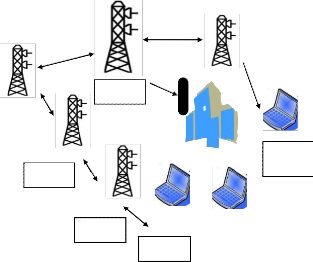
Fig 1. Multi-hop Re lay Netw ork architectures
Source: [3]
2 M ATERIALS AND SCEN ARIO
This study pr ovides guidelines on the design of 802.16j systems operating in transpar ent mode, the deployment scenario(s) and system configur ation that would lead to a significant thr oughput gain. Differ ent deployment scenar ios containing a Host, Base station (BS), Relay station (RS) and Subscr iber station (SS) wer e consider ed, all aimed at optimising thr oughput among their r espective topology. The Relay station (RS) position w as manipulated w ith its
Communication Technology Department at The University of Trinidad and Tobago,Trinidad and Tobago, E-mail: naresh.singh1@hotmail.com
IJSER © 2012 http :// www.ijser.org
Inte rnatio nal Jo urnal o f Sc ie ntific & Eng inee ring Re se arc h, Vo lume 3, Issue 2, February -2012 2
ISS N 2229-5518
corr esponding Base and Subscr iber station to determine the r eaction in terms of thr oughput.
The IEEE 802.16j netw or k was simulated into an NCTU networ k simulator . NCTUns w as mainly chosen because it supports both the transpar ent and non -transpar ent modes defined in the IEEE 802.16j standar d and is very easy to manoeuvr e and use via its highly-integrated Graphics User Inter face (GUI) envir onment [4] . The simulator also supports the scenarios and parameters that would lead to the successful completion of the pr oj ect.
3 RESULTS AND D ISCUSSION
3.1 Scenario 1
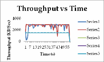
The Subscr iber station (SS) was at a fixed location outside the range of the Base station (BS). The Relay station (RS) was placed betw een the Base Station (BS) and the Subscr iber station (SS). The height of the Base St ation, Relay Station and the Subscr iber Station was set to 20 meter s, 15 meter s and 1.5 meter s r espectively . The pow er of the Base Station, Relay Station and the Subscr iber Station w as set to 43 dbm, 43 dbm and 35 dbm r espectively. The Input Output Thr oughput average values w er e r ecor ded as shown in TABLE 1. The Average Input Output Thr oughput decr eased as the Subscr iber Station (SS) distance incr eased fr om the Relay Station (RS) up to a certain distance. The distance of 275.600 meter s betw een the Subscr iber Station (SS) and the Relay Station (RS) gave the low est Aver age Input Output throughput . The distance of 225.505 meters betw een the Subscr iber Station (SS) and the Relay Station (RS) also gave a low Average Input Output thr oughput. Subscr iber Station (SS) was placed at a constant distance of 950 meter s fr om the Base Station (BS).
TABLE 1
Throughput for a height of 20 meters and 15 meters for the
Base station (BS) and Relay station (RS)
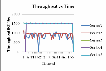
Fig 2. Graph f or Table 1 Average Throughput values
3.2 Scenario 2
Scenar io 2 focused mainly on incr easing the height at the Base Station (BS) and Relay Station(RS) for the same distances betw een the Base Station (BS) and Relay Station (RS) as in TABLE 1. TABLES 2 and 3 show the Average Input Output Thr oughput values for change in height and distance betw een the BS and the RS. The heights of the Base Station(BS) and the Relay Station was incr eased to 30 meters and 20 meters r espectively. It can be seen fr om TABLE 2 that the thr oughput incr eased for the distances of 275.600 and 225.505 meter s w ith the incr ease in heights of the Base Station (BS) and Relay Station(RS). Table 3 shows that fur thur incr easing the heights of the Base Station (BS) and Relay Station(RS) to 45 meters and 35 meters impr oved the Average Input Output Thr oughput at the distances of 275.600 and 225.505 meters.
IJSER © 2012 http :// www.ijser.org
Inte rnatio nal Jo urnal o f Sc ie ntific & Eng inee ring Re se arc h, Vo lume 3, Issue 2, February -2012 3
ISS N 2229-5518
The Subscr iber Station (SS) was placed at a constant distance of 950 meters fr om the Base Station (BS).
TABLE 2
Throughput for a height of 30 meters and 20 meters for the
Base station (BS) and Relay station (RS)
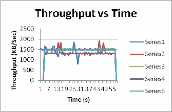
Fig 3. Graph f or Table 2 Average Throughput values
TABLE 3
Throughput for a height of 45 meters and 35 meters for the
Base station (BS) and Relay station (RS)
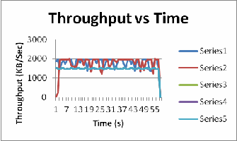
Fig 4. Graph f or Table 3 Average Throughput values
3.3 Scenario 3
Scenar io 3 focused mainly on incr easing the pow er at the Base station (BS) and Relay station (RS) so as to determine the RS placement which yields the maximum thr oughput. TABLE 4 shows the thr oughput for change in power by furthur incr easing the power of the Base Station (BS) and Relay Station(RS) to 55 dbm and 55 dbm. The Aver age Input Output Thr oughput at the distances of 275.600 and 225.505 meters showed a lar ge incr ease. The Subscr iber Station (SS) was placed at a constant distance of 950 meters fr om the Base Station (BS).
TABLE 4
Throughput for a power of 55 dbm and 55 dbm for the
Base station (BS) and Relay station (RS)
IJSER © 2012 http :// www.ijser.org
Inte rnatio nal Jo urnal o f Sc ie ntific & Eng inee ring Re se arc h, Vo lume 3, Issue 2, February -2012 4
ISS N 2229-5518
height and pow er ar e significant factors w hen distance b etw een Base and Relay Station is lar ge.
4 Future Work
WiMAX IEEE 802.16j is an evolving technology and ther e is a lot of r oom for r esearch. The following ar e a few suggestions for futur e w or k:
Operating in a Non-Transpar ent mode RS (NT-RS) envir onment. This mode allows for hops gr eater than tw o.
Applying a variety of modulation schemes to the
r elay-based networ k, both in Tr anspar ent mode RS (T-RS) and NT-RS. These include Phase Shift Key (PSK), Quadratur e Phase Shift Key (QPSK) and
Quadratur e Amplitude modulation (QAM).
References
[1]Masato , O. C .Zhu and V io re l, “Multiho p Re lay e xte nsio n fo r
WiMAX ne two rks-ove rv ie w and be ne fits o f IEEE 802.16j standard”,
2008, Fujitsu Sci. Tec h. J., 44: 292 -302,
http://www.fujitsu.co m/do wnlo ads/MAG /vo l44 -3/pape r10.pdf [2] A.F.Bay an, T.Wan, S.Ramadass, “De lay Analy sis and Syste m Capac ity Co ntro l fo r Mo bile WiMAX Re lay Ne two rks”, Jo urnal o f Co mpute r Sc ie nce 6, 2010, pp1108 -1114
[3] V.Abe l, “S urvey o f Curre nt and Future Tre nds in Sec urity in Wire le ss
Ne two rks”, Inte rnatio nal Jo urnal o f Sc ie ntific & Eng ine e ring Re se arc h
(ISSN 2229-5518), April 2011
[4]S -Y. Wang and Y-B. Lin, “NCTUns ne two rk simulatio n and e mulatio n
fo r wire less reso urce manag e me nt”, Jo hn Wiley & Sons, Ltd, 2005, pp4
Fig 5. Graph f or Table 4 Average Throughput values
4 Conclusion
Thus fr om the specific scenar ios conducted above, it was seen in Scenar io 1, that as the distance between the Relay Station and the Subscr iber Station was incr eased the Aver age Input Output Thr oughput decr eased up to a certain distance, w hen the distance betw een the Relay Station (RS) and the Subscr iber Station (SS) w as lar ge as shown in TABLE 1. At the same distances of the Relay Station (RS) and Subscriber Station (SS) placements, w ith incr ease in the heights and tr ansmit pow er of the Base and Relay stations significant incr ease in thr oughput was found for distances as shown in TABLES 2,3 and 4 at distances wher e the distance betw een the Relay Station (RS) and the Subscriber Station (SS) w as lar ge. Thus, this implies
IJSER © 2012 http :// www.ijser.org