International Journal of Scientific & Engineering Research, Volume 2, Issue 6, June-2011 1
ISSN 2229-5518
Thermal Performance of Thermosyphon Charged by Nanofluid for Cooling Electronic Component
M. G. Mousa
Abstract— In present work a experimental study based on thermosyphon is investigated using a solid nano-particles added to water as a working fluid. Tests are made on a thermosyphon. The experiment was performed in order to measure the temperature distribution and com- pare the heat transfer rate of the thermosyphon with the nanofluid and with pure water. The tested concentration level of the nano-particles is
0%, to 1.2%. Results show that the addition of 1.2% (by volume) of Al2O3 nano-particles in water presented improved thermal performance compared with the operation with pure water. Results showed that the total thermal resistance, using Al2O3-water based the nanofluid is en- hanced by 57% at f equal 1.2 % compared to that of pure water, depending on filling ratio and volume fraction of the nano-particles in the base fluid. The experimental data are compared with the available literature and discrepancies between results are discussed.
Keywords - Two phase loop Thermosyphon, Thermal Performance, Nanofluids, Cooling of Electronic Devices.
Cp Specific heat, J/kg K
FR Filling ratio
I Current, Amp
k thermal conductivity
L Length, m
N Number of thermocouples
Q Input heat rate, W
TR Total thermal resistance, K/W
T Temperature, K
V Applied voltage, Volt
Z Vertical coordinates parallel to the test section ,m
Greek Symbols
� Volume fraction of nano-particles, %
p Density, kg/m3
µ Dynamic viscosity, N.S/m2
Subscript
c Condenser
e Evaporator
nf Nanofluid
m Base fluid
RR Reduction factor in thermal resistance, --
—————————— • ——————————
IJSER © 2011 http://www.ijser.org
International Journal of Scientific & Engineering Research, Volume 2, Issue 6, June-2011 2
ISSN 2229-5518
1. INTRODUCTION
Heat dissipation from high performance microprocessors is approaching 100 W/cm2. At this level, conventional cooling solution cannot match the demand from this high perfor- mance of components. In the present a new way to resolve the thermal challenges by developing and implementing an innovative low cost compact loop thermosyphon. The progress in the PC industry of high thermal loading coupled with high flux levels demands exploration of new heat transfer augmentation mechanisms. A nanofluid is emerg- ing a s a l t er n at i v e heat t r a ns f er fluids. The term ‘Na- nofluids’ is used to indicate a special class of heat transfer fluids that contain nano-particles (<~100 nm) of metallic or non metallic substances uniformly and stably suspended in a conventional fluid. To solve the problem of growing heat generation by such electronic equipment, two- phase change devices such as heat pipe and thermosyohon cooling systems are now used in electronic industry and attracted the attention of several researchers [1].
The traditional working fluids have poor heat trans- fer properties compared to most solids. Therefore, Argonne National Laboratory has developed a new class of heat transfer fluids called “Nanofluids”, which are engineered by suspending ultra-fine of metallic or nonmetallic nanometer dimension particles in traditional fluids such as water, en- gine oil, ethylene glycol by Choi, and Eastman [1]. Some experimental investigations have revealed that nano-fluids have remarkably higher thermal conductivity and greater heat transfer characteristics than conventional pure fluids
Two phase loop Thermosyphon, TPLT, is a very simple and very efficient heat transfer device. Basically, it can be considered as a super-thermal conductor that trans- mits heat at small temperature difference by evaporation and condensation of the working fluid. The thermosyphon utilizes the local gravitational acceleration for the return of condensate from the condenser to the evaporator. Thermo- syphon is considered as a passive device because heat is transferred inside a tube by buoyancy force only. Thermo- syphon has a simple construction with no moving parts. Thus, it can be easily manufactured at low fabrication cost. Because of its small thermal resistance, thermosyphon trans- fers large amount of heat rates at small temperature differ- ences. Heat transfer in thermosyphon is studied by many researchers. But, there is a need to investigate the effect of some parameters such as nanofluid concentration and other parameter especially from experimental point of view.
The heat transfer in a two-phase thermosyphon, TPLT, operating with a fluid in the near critical state was studied experimentally by Gross and Hahne, [2]. The fluid pressure, heat flow rate and tube inclination angle were ex- perimentally investigated. Refrigerant-115 was used as a working fluid in the near critical state.
Steady state performance of a thermosyphon with tube separator was presented by Lin and Faghri, [3]. A one- dimensional steady-state mathematical model describing natural circulation two-phase flow thermosyphon with tube separator was presented. The theoretical results showed that a single liquid region in the lower part of the evaporator was
available if the heat rate and operating temperature were fairly low.
Single-phase and two-phase heat exchangers for power electronic components were presented by Gillot et al., [4]. The experiment performed to assess the feasibility of single-phase and two-phase micro heat sinks applied to the cooling of power components. After a brief recall of the principal characteristics of a power component insulated gate bipolar transistor, experimental measurements were described for multi-chip modules cooled by single-phase or two-phase heat sinks machined in a piece of copper.
Two-phase loop compact thermosyphon was pre- sented by Beitelmal et al., [5]. Heat dissipation from high performance microprocessors had a limiting value of 100
W/cm². They adopted a new way to resolve the thermal challenges by developing and implementing an innovative low cost compact loop thermosyphon.
Integrated thermal management techniques for high power electronic devices were presented by Mcglen et al., [6]. In electronics industry, miniaturization of silicon com- ponents and enhanced performance has led to high power electronic devices with high packing densities. That has identified the future development of very high heat flux components. They reviewed the development of micro- processing technology and proposed a project to develop combined two-phase heat transfer and heat pipe technology with forced air convection and liquid condenser systems
An experimental investigation of thermosyphon thermal performance carried out using water and dielectric heat transfer liquids as the working fluid was performed by Jouhara et al., [7]. The copper thermosyphon was 200 mm long with an inner diameter of 6 mm. Each thermosyphon was charged with 1.8 ml of working fluid and tested usin an evaporator length of 40 mm and a condenser length of 60 mm. The thermal performance of the water charged thermo- syphon outperformed the other three working fluids (FC-84, FC-77 and FC-3283) in both effective thermal resistance as well as maximum heat transport. However, these fluids, offered the advantage of being dielectric which may be bet- ter suited for cooling applications of sensitive electronics. Furthermore, they provided adequate thermal performance up to approximately 50 W, after which liquid entrainment compromised the thermosyphon performance.
Visual observation of flow patterns in the condenser and heat transfer measurements were obtained by Maezawa and Takuma, [8] using a vertical annular thermosyphon. Refrigerant-115 was used as a working fluid. As a result of visual observations, ripples (interfacial waves) were gener- ated on the condensate film surface when the corresponding film Reynolds number exceeded approximately 20, and con- densation heat transfer was promoted.
Ueda et al. [9] performed an experiment with verti-
cally arranged closed two-phase thermosyphon. The charac- teristics of heat transfer of boiling in the heating section and condensation in the cooling section were investigated. The condensation heat transfer coefficient of the cooling section showed a decreasing trend with increasing wall temperature difference. However, its value was considerably lower under high vapor velocities. The boiling heat transfer characteristic
IJSER © 2011 http://www.ijser.org
International Journal of Scientific & Engineering Research, Volume 2, Issue 6, June-2011 3
ISSN 2229-5518
of the heating section could be approximated by the empiri- cal correlation given for pool boiling.
Tanaka and Koshino, [10] performed series of ex- periments with a copper-water wickless heat pipe. The in- fluence of working fluid charge and inclination angle on the heat transfer coefficients of the evaporator and the condens- er were studied. The experimental results indicated that, as the heat transfer coefficient in the case of liquid film is larger than that in case of liquid pool.
Lin and Shyu, [11] experimentally studied the geyser boiling in a vertical annular closed two-phase ther- mosyphon. The experimental parameters considered were the heat load, condenser temperature, degree of liquid fill and length of the evaporator. It was clear that, geyser boiling i occurred more frequently and irregularly at high heat load. Wall temperature measurements indicated that the period of geyser boiling is shorter at higher heat load, shorter evapo- rator length and smaller liquid fill.
Noie et al, [12], studied experimentally the two phase closed thermosyphon in heat transmission. Fluids, with nano-particles suspended in them, were used as work- ing fluids. The experimental results, at different input pow- er, showed that the used of nanofluids increases the efficien- cy of two phase closed thermosyphon by 14.7%.
Mehta and Khandekar [13] and Khandekar et al [14and 15]
investigated experimentally the overall thermal resistance of a closed two-phase thermosyphon using pure water and various water based nanofluids (of Al2O3, CuO and Lapo- nite clay) as working fluids. All these nanofluids were show- ing the thermal performance greater than pure water. The behavior of nanofluids is explained in the light of pool boil- ing dynamics and the interplay of nucleating cavities with wettability of the nanofluids.
Zhen, et al [15] the experimental study was carried out to understand the heat transfer performance of a miniature thermosyphon using water-based carbon nanotube (CNT) suspensions as the working fluid. The suspensions consisted of deionized water and multi-wall carbon nanotubes with an average diameter of 15 nm and a length range of 5-15 lm. Experiments were performed under three steady operation pressures of 7.4 kPa, 13.2 kPa and 20 kPa, respectively.
The aim of the present work is to study experimen- tally, the thermal performance of thermosyphon cooling
system in electronic equipment. The effect of different oper- ating conditions on the thermal performance of the con- structed thermosyphon is study. These conditions involve the type of working fluid (pure water and Al2O3 - water based nanofluid); filling ratio of the working fluid; volume fraction of nano- particles in the base fluid, and heat input rate. The additional aim of the loop thermosyphon is to re- duce acoustic noise in the system by eliminating the existing heat sink fan.
2. Description of Experimental Apparatus
The nano-particles used in these experiments are AL2O3. To reduce the contact thermal resistance between the heater and the thermosyphon surface, the heated and adia- batic sections are insulated by Bakelite (0.233 W/m-K) and glass fiber wool (0.034 W/m-K). The ratio between the thermal resistances of heat flow from heater to the surround-
ing air compared to that from heater to thermosyphon is about 0.1%.
In this work adopts pure water and Al2O3-water based the nanofluid as working fluids. The size of used na- no particles is 40 nm. A schematic layout of the experimen- tal test rig is shown in Fig.1. The thermosyphon is divided into three sections; the evaporator and condenser are made of copper cube of 100.0 mm length and 1.0mm wall thick- ness and the adiabatic tubes which are 100.0mm length, 6.37 mm diameter and 0.85 mm thick. In the thermosyphon, the heat flux is generated by an electric heater (10). Pure water or nanofluid (16) is used as working fluid, and the vapor generated at the evaporator (1) is moved to the condenser (3) through the insulated vapor tube (2). The condensate returns back to evaporator by gravity through the insulated down- comer (4). The temperature along the thermosyphon walls are measured by Copper-Constantan thermocouples (K- type). Thermocouples are connected to a digital temperature recorder via multi-point switch connected to a data acquisi- tion system. The thermosyphon is evacuated through a va- cuum line (14) by vacuum pump and charged with working fluid through charging line (13). The electric power sup- plied to the evaporator heater which is similar to the heat of CPU (10) is measured by an ammeter (9) and voltmeter (8). The value of voltage can be adjusted by using an autotrans- former (7). The voltage drop across the heater is varied from
5 to 35 Volt and the resistance of the heater is 20 Q. A.C.
voltage stabilizer (6) is used to ensure that no voltage fluctu- ation occur during the experiments. The operating pressures are 10, 12, and 15 kPa. The distribution of thermocouple along the thermosyphon is shown in figure 1.
2.1. Experimental Procedure
In the experimental work, the effect of filling ratio, FR, (volume of liquid over total evaporator volume) and heat flux are examined. The experimental runs are carried out according to the following steps:
1. The thermosyphon is evacuated and charged with a certain predetermined amount of working fluid and then the current and voltage are adjusted.
2. The supplied electrical power is manually adjusted to
the desired value using the autotransformer.
3. As noted, the steady state condition is achieved after a
time period of about 120 min, during which necessary adjustments in the input power is made. Thereafter, the readings of thermocouples, voltage and current are rec- orded as follows:
The reading of thermocouples at the thermosy- phon surface and ambient temperature are rec- orded sequentially using the selector switch.
The voltage and current of the heater are measured
to determine the value of the applied heat flux.
4. After finishing the above experimental steps, power is
changed to another value and step 3 is repeated.
5. The thermosyphon is charged with another adjusted value of working fluid such that the filing ratio, FR, is changed using the following values: 32.0%, 40.0%,
48.0%, 56.0%, 64.0%, 72.0%, 80.0%, 88.0%, 96.0%, and
100.0% respectively. Then steps 1 through 4 are re-
peated.
IJSER © 2011 http ://www.ijser.org
International Journal of Scientific & Engineering Research, Volume 2, Issue 6, June-2011 4
ISSN 2229-5518
Preparation of nano-particle suspensions is applied the nanofluids in heat transfer enhancement. In the present study, Al2O3 nano-particles are dispersed in pure water by ultra sonic without using any dispersant or stabilizer to pre-
vent any possible changes of chemical properties of the
specific heat, viscosity, and thermal conductivity after [21-
23]. One can assume that the nano-particles are well dis-
persed within the base-fluid. Thus, the effective physical
propeVrties are described by classical formulas as;
nanofluid due to presence of additions. Nanofluids of 0.1%, to 1.2% volume fraction of particles are prepared. After
p nf
= (1 - � )p m + �p p
(6)
measuring the equivalent volume to the required mass of
nano-particle powder, they were mixed with distilled water
p nf Cp nf = (1 - � )pm Cp m + � p P Cp p
(7)
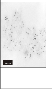
in a flask subject to ultra sonic for about 4 h. No precipita- tion or settlement of the nano-particles is observed after 24 h of settling the suspension. The micrograph of Al2O3 nano- particles in pure water is shown in figure 2 at concentration,
� , equal to 1.0%.
The effective dynamic viscosity of the nanofluid can be calculated using different existing formulas that have been obtained for two-phase mixtures. The following rela- tion is the equation for a viscous fluid containing a dilute suspension of small, rigid, spherical particles.
1
2.2. Calculations procedure:
nf
![]()
= m
(1 - � )2.5
(8)
The obtained measured data of temperature and
knf
k p
![]()
= km (
+ 2 km
- 2� (km
- km ) )
power are used to calculate the heat rate and the total ther-
k p + 2 km + (km
- km )
mal resistance.
At steady state condition, the produced heat gener-
ated by the electrical heating is given by the following equa- tion to calculate the heat transfer rate and check the error analysis in experimental data may have resulted from:
Where, � is the ratio of the volume of nano-particle to volume of the base fluid.
The relevant thermo-physical properties of the solid nano-particles (Al2O3) used in the present study are: Cpp
Q = I X V
(1)
=773 J/kg.oC, p =3880 kg/m3 ,and kp =36 W/m.oC .from
Where, Q, I, and V are the input heat rate, the electrical cur- rent in Amp, and the applied voltage drop a cross the heat element terminals.
[21,23]
One can calculate the reduction factor in total thermal
Thus of the
resistance of thermosyphon charged with nanofluid by refer-
Q = f ( I , V )
(2)
ring its thermal resistance to that charged with pure water,
Error analysis of heat transfer rate is obtained by the follow- ing relation;
1 / 2
expressed as
RR = (TRm –TRef)/TRm (9)
The average temperature of the surface of the eva-
W = T
i
aQ 2
![]()
WV )
aV
+ ( =aQ
aI
2
WI ) I
(3)
porator section increased from 60 to 100 oC. Data are rec- orded when the system reached steady-state condition. The maximum error in thermal resistance is +8.4 %
The experimental determination of the thermal per-
formance of the thermosyphon requires accurate measure-
ments of evaporator and condenser temperatures as well as
the power transferred. Characterizing evaporator and con-
denser temperatures is, relatively, a straightforward task.
One can obtain the average temperature along the evapora- tor and condenser surfaces are expressed as:
Experiments were performed under three steady operation pressures of 10.0 kPa, 12 kPa and 15 kPa, respec- tively
3. Results and Discussion
In the present section, experimental results involve the study of convective heat transfer in thermosyphon. Total thermal resistance is introduced. Using wall temperature
= "LTci
, (4)
readings, the total resistance of the tested thermosyphon is
e c
e c calculated for different values of operating parameters. The
Where Ne, Nc are the number of thermocouples on the eva- porator, seven thermocouple, and condenser, seven thermo- couple, respectively. The obtained data for temperatures and heat input rate are then used to calculate the total thermal resistance using the following relation:
experiments for thermosyphon are carried out varying the
values of heat source from 10 to 60 W. Pure water and the
nanofluid used as working fluids are charged with filling
ratios, FR, of 32.0%, 40.0%, 48.0%, 56.0%, 64.0%, 72.0%,
80.0%, 88.0%, 96.0%, and 100.0% respectively. Nano-particle concentration, � are varied from 0.0% to 1.2%. Finally, the
obtained experimental results are compared with the values![]()
(5)
obtained from available literature.
3.1. Thermal performance of thermosyphon using pure
The physical properties used for nanofluid are cal- culated from water and nano-particle properties at average bulk temperature using following correlations for density,
water as a working fluid
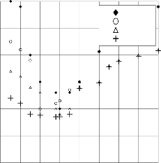
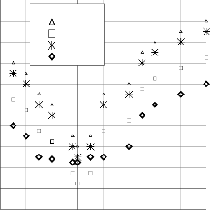
Figure 3 illustrates the surface temperature along the thermosyphon for different heat input rates (10, 20, 30 and 60 W) at fixed filling ratio, FR of 48% and operating
IJSER © 2011 http://www.ijser.org
International Journal of Scientific & Engineering Research, Volume 2, Issue 6, June-2011 5
ISSN 2229-5518
pressure of 15 kPa. As expected, the surface temperature decreases with increasing the distance from the evaporator, for any heat input rate. The surface temperature increases with the increase of heat input rate at a certain position along the thermosyphon. The adiabatic operating tempera- tures ranged from 40°C to 65°C. Externally controlled condi- tions are kept identical for baseline experiments with pure water.
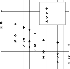
Figure 4 illustrates the variation of the total thermal resis- tance, TR, with the filling ratio, FR, at different heat input rates, Q. It can be noticed that, TR decreases with increasing FR up to a value of 48%, after which the total thermal resis- tance, TR, starts to increase with increasing FR due to the increase of liquid inside the evaporator. The total thermal resistance, TR, is decreases as the heat input rate increases.
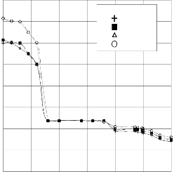
Figure 5 illustrates the surface temperature along the thermosyphon for different heat input rates (10, 20, 30 and 60 W) at fixed filling ratio, FR of 48% and operating pressure of 12 kPa.. Moreover, the surface temperature de- creases with increasing the distance from the evaporator, for any heat input rate. At any certain position along the ther- mosyphon, the surface temperature increases with increas- ing heat input rate. The temperatures measured in case of operating pressure 12 kPa is lower than those measured in operating pressure 15 kPa see in (figures 3 and5)
3.2. Thermal performance of thermosyphon using nanoflu-
id as a working fluid
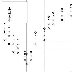
Figure 6 illustrates the surface temperature along the thermosyphon for different heat input rates (10, 20, 30 and 60 W) at fixed filling ratio, FR of 48% and operating pressure of 15 kPa. The surface temperature decreases with increasing the distance from the evaporator, for all heat in- put rate.
Figure 7 illustrates the variation of the total thermal resistance of the heat pipe, R with the filling ratio for Al2O3- water based nanofluid of � = 0.5% at different heat input rates (10, 20, 30, and 60 W). As shown in the figure, TR de- creases with the increase filling ratio up to a value of FR equals to 48%, where its value starts to increase with increas- ing FR. It can be also noticed in the figure that the thermal resistance, TR, gets decreases as the heat input rate increas- es.
Figure 8 illustrates the variation of the total thermal resistance, TR, of the thermosyphon, with the filling ratio for Al2O3-water based nanofluid of � = 0.5% at different heat input rates (10, 20, 30, and 60 W). As shown in the figure, TR decreases with the increase filling ratio up to a value of FR equals to 48%, where its value starts to increase with in- creasing FR. It can be also noticed in the figure that the thermal resistance, TR, decreases as the heat input rate in- creases.
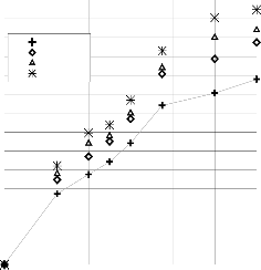
Figure 9 shows the variation of the total thermal resistance of the thermosyphon, TR, with volume fraction of the nano- particle in the base fluid, � at different heat input rate (10,
20, 30, and 60 W). Over the tested range of �, while keeping the filling ratio of 48%, the percentage enhancement in TR ranged from 67% at � = 1.2% compared to that calculated using pure water. The addition of nano-particles has illu-
strated that during nucleate boiling some nano-particles
deposit on the heated surface to form a porous layer. This layer improves the wet ability of the surface considerably. The thermal conductivity of the working fluid is preferably high in order to minimize the temperature gradient. Thus, the thermal resistance of the fluid will be minimized. Ther- mal resistance of thermosyphon is caused by the formation of va- por bubble at the liquid–solid interface. A larger bubble nuclea- tion size creates a higher thermal resistance that prevents the transfer of heat from the solid surface to the liquid [23]. The sus- pended nano-particles tend to bombard the vapor bubble during the bubble formation. Therefore, it is expected that the nucleation size of the vapor bubble is much smaller for the fluid with sus- pended nano-particles than that without them. One can estimate the relation between the percentage reduction factor in total thermal resistance, TR, RR, as a function of concentration as follow;
RR=0.84 �-0.3�2 (10)
The error in calculated thermal resistance is predicted by the above suggested around ±12 %.
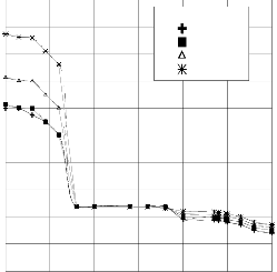
3.3. Comparison between present and previous results
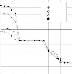
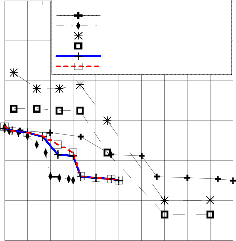
Figure 10 shows a comparison between the present experimental results with those reported by Noie et al [12] in case of using pure water as a working fluid with FR equals to 0.5. It can be observed that the present experimen- tal results for the used two working fluids have the same trend as those reported by Noie et al [12].The difference be- tween both results when using pure water may be attributed to the difference in heat uncertainty in measurements.
4. Conclusions
In this paper the thermal enhancement of the thermosyphon
performance, using Al2O3 nanofluid as the working fluid. In the present case, the DI-water with Al2O3 nano-particles in thermosy- phon is experimentally tested. Conclusions may be drawn from the results of the performance tests. The more Al2O3 nano- particles are dispersed in the working fluid enhancement of the thermosyphon performance expressed by of the performance curves (thermal resistance as a function of the volume fraction,
�). The thermal resistance of the thermosyphon with nano- particle solution is lower than that with DI-water. It is shown that
the thermal resistance decreases as the concentration increases.
Results indicate that the Al2O3 nanofluid has remarkable potential as working fluid for thermosyphon of higher thermal perfor- mances. In order to obtain high heat transfer performance, it is necessary to fill between 40% and 60% of the evaporator inner volume. This conclusion is true for thermosyphons. For most ex- amined conditions, the thermal resistance is improved by about to
60 % by increasing the nanofluid concentration to �
References
(1) Choi, S.U.S, "Enhancing thermal conductivity of fluids with nano-particles", in: D.A. Siginer, H.P. Wang (Eds.), Developments and Applications of Non-Newtonian Flows, in: FED, vol. 66, ASME, NY, pp. 99-103,1995.
(2) Gross, U., and Hahne, E.,"Heat transfer in a two-phase
thermosyphon operating with a fluid in the near critical
state," Int. J. Heat Mass Transfer, Vol. 28, pp.589-601,
1985
(3)Lin, L., and Faghri, A.," Steady – state performance of a thermosyphon with tube separator ", Applied Thermal Engineering Vol. 17. No. 7, pp. 661-679, 1996.
(4) Gillot, C., Bricard, A., and Schaeffer, C.," Single- and two-phase heat exchangers for power electronic compo-
nents", Int. J. Thermal Sciences Vol. 39,PP 826–832, 2000.
IJSER © 2011 http ://www.ijser.org
International Journal of Scientific & Engineering Research, Volume 2, Issue 6, June-2011 6
ISSN 2229-5518
(5) Beitelmal, M. H., and Patel, C. D.," Two-Phase Loop: Compact Thermosyphon", Internet Systems and Storage Laboratory, 2002.
(6) Mcglen, R. J., Jachuck, R., and Lin, S.," Integrated ther- mal management techniques for high power electronic devices", Applied Thermal Engineering ,Vol.24 ,PP 1143–
1156, 2004.
(7) Jouhara, H., Martinet, O., and Robinson, A.J., “Experi-
mental Study of Small Diameter Thermosyphons
Charged with Water", FC-84, FC-77 & FC-3283- 5th Eu-
ropean Thermal-Sciences Conference, The Netherlands,
2008.
(8) Maezawa, S. and Takuma, M., “Heat transfer characte-
ristics of the R113 annular two-phase closed thermosy-
phon,” JSME series II, Vol. 31, pp. 469-476, 1988.
(9) Ueda, T., Miyashita, T., and Chu, P., “Heat transport
characteristics of a closed two-phase thermosyphon,” JSME series II, Vol. 32, pp. 239-246, 1989.
(10) Tanaka, O., and Koshino, H., “Heat transfer characte- ristics of a copper-water wickless heat pipe,” JSME series B, Vol. 60, pp. 2826-2832, 1994.
(11) Lin, T. F., and Shyu, R. J., “Experimental investigation
of geyser boiling in an annular two-phase closed thermo- syphon,” Int. J. Heat Mass Transfer, Vol. 38, pp. 295-307,
1995.
(12) Noie, S.H., Zeinali, S., Kahani, M., and Nowee, S. M., “
heat transfer enhancement using Al2O3/ water nanofluid in a two phase closed thermosyphon International Jour-
nal of Heat and Fluid Flow 30 , pp.700–705, 2009.
(13) Mehta, B., and Khandekar, S., 'Two-phase closed ther-
mosyphon with nanofluids' 14th International Heat Pipe
Conference (14th IHPC), Florianópolis, Brazil, April 22-
27, 2007.
(14) Khandekar, S., Joshi, Y., and Mehta, B., "Thermal per-
formance of closed two-phase thermosyphon using na-
nofluids", International Journal of Thermal Sciences, 47
pp.659-667, 2008.
(15) Khandekar, S., Joshi, Y., and Mehta, B.," Thermal per- formance of closed two-phase thermosyphon using na- nofluids "International Journal of Thermal Sciences 47, pp. 659–667, 2008.
(16) Liu,Z. , Yang, X., Wang,G., and Guo, G. "Influence of carbon nanotube suspension on the thermal perfor-
mance of a miniature thermosyphon" International Jour- nal of Heat and Mass Transfer vol.,53 , pp. 1914–1920,
2010.
(17) Liu, Z., Yang, X., and Guo, G., " Effect of nanoparticles
in nanofluid on thermal performance in a miniature
thermosyphon, Journal of Applied Physics, 102, 013526,
2007.
(18) Huminic, G., Huminic, A., Morjan, I., and Dumi- trache, F., "Experimental study of the thermal perfor- mance of thermosyphon heat pipe using iron oxide na- no-particles" International Journal of Heat and Mass Transfer 54, pp. 656–661, 2011.
(19) Xue, H., Fan, J., Hu, Y., Hong, R., and Cen, K., "The interface effect of carbon nanotube suspension on the thermal performance of a two-phase closed thermosy- phon", Journal of Applied Physics, 100, 104909, 2006.
(20) Parametthanuwat, T., Rittidech, S., and Pattiya A., “A
correlation to predict heat-transfer rates of a two-phase closed thermosyphon (TPCT) using silver nanofluid at normal operating conditions” International Journal of Heat and Mass Transfer 53, pp. 4960–4965, 2010.
(21)Collier, G., and Thome, J.," Convective Boiling and Condensation, Clarendon Press, Oxford,
1996.
(22) Faghri A., Heat Pipe Science and Technology, Taylor
and Francis, 1995.
(23)Das, S. K., Choi, U.S., Yu,W., and Pradeep, T., "Na-
nofluid Science and Technology", Wily-Interscience,
2007.
IJSER © 2011 http://www.ijser.org
Fig.2 micrograph of Al2O3 the nano- particles
52
FR = 40%
Q= 10 W
Q= 20 W
48 Q= 30 W Q= 60 W
44
40
Figure (1) Schematic layout of the test
rig used in experimental work and 36
thermocouple distribution.
32
0 100 200 3
Distance, mm
Figure 3 Temperature distribution along the thermosy- phon surface for different heat input rate at operating pressure equal kPa.
IJSER © 2011 http://www.ijser.org
8 International Journal of Scientific & Engineering Research, Volume 1, Issue 2, November-2010
ISSN 2229-5518
0.4
0.3
48
Q = 10W Q = 20 W Q = 30 W Q = 60 W
44
FR = 48%
Q= 10 W
Q= 20 W Q= 30 W Q= 60 W
40
0.2
36
0.1
20 40 60 80 100
F i l l i n g R a t i o, FR%
32
0 100 200 300
Distance, mm
Figure 4 Variation of the total thermal resistance with filling ratio at different heat input rate
Figure 6 Temperature distribution along the thermosyphon surface for different heat input rate at operating pressure equal kPa.
0.32
52
FR = 48%
Q= 10 W
Q= 20 W
48 Q= 30 W Q= 60 W
0.28
0.24
�= 0.5%
Q = 10 W
Q = 20 W Q = 30 W Q=60 W
0.2
44
0.16
40
20 40 60 80 100
F i l l i n g R a t i o, FR %
36
Figure 7 Variation of t hermal resistance with filling ratio
at different heat input rate
32
0 100 200 300
Distance, mm
Figure 5 Temperature distribution along the thermosy- phon surface for different heat input rate at operating pressure equal kPa.
0.32
0.28
�= 0.5%
Q = 10 W
Q = 20 W Q = 30 W Q = 60 W
0.24
0.2
0.16
20 40 60 80 100
F i l l i n g R a t i o, FR %
Figure 8 Variation of thermal resistance with filling ratio at different heat input rate
IJSER © 2011 http://www.ijser.org
0.35
0.3
0.25
0.2
FR=0.45
Q = 10 W Q = 20 W Q = 30 W Q = 60 W
0 100 200 300
80
Comparsion
Noie et al @ Q=48 W and �=0.0%
Noie et al @ Q=48 W and �=1.0% Noie et al @ Q=97.1 W and �=0.0% Noie et al @ Q=97.1 W and �=1.0% Present @ Q=20 W and �=0.0% Present @ Q=20 W and �=1.0%
60
0.15
0.1
40
0.05
0 0.2 0.4 0.6 0.8 1 1.2
Volume Fractionof nano-particle, �%
Figure 9 Variation of thermal resistance with volume frac-
tion of nano-particles
0.7
20
0 200 400 600 800 1000
Vertical Distance, mm
0.6
0.5
Q = 10 W Q = 20 W Q = 30 W Q = 60 W
Figure 11 Comparison of the present results with available literature at different value of heat input rate
0.4
0.3
0.2
0.1
0
0 0.4 0.8 1.2
Volume fraction ofNano Particles, � %
Figure 10 Reduction factor of total thermal resistance at different volume fraction of the nano-particles, �
IJSER © 2011 http://www.ijser.org