The research paper published by IJSER journal is about Thermal modeling Of Solar Pond In Matlab 1
ISSN 2229-5518
Thermal modeling Of Solar Pond in Matlab
Mr. Md. Irfan Ali, Ms. S. Madhu, Mr. R. Yuvaraj
————————————————————
olar energy is an abundant and renewable energy source. The annual solar energy incident at the ground in india is about 20,000 times the current electrical energy consump- tion. Solar energy can be collected and stored effectively as sensible heat in a solar pond containing dissolved salt (NaCl), the latter helping to create a stable density-gradient. The sto- rage capacity depends on the ponds depth: the salt concentra- tion increasing with depth in the solar pond. It has been rea- lized recently that solar ponds can be an economically-viable source of heat. The use of solar energy in India has been very limited. This is because solar energy is a dilute energy source, and hence energy must be collected over large areas resulting in initial capital investment, moreover it is also an intermittent energy source. Hence solar energy systems must incorporate storage in order to take care of energy needs during nights and on cloudy days. This results in further increase in the cap- ital cost of such systems. One way to overcome these problems is to use a large body of water for the collection and storage of solar energy. Another useful way is to build a physical model of solar pond in simulink using thermal library and giving real working inputs and getting the simulated results. By analys- ing the simulated results we can construct the real working
practical model, which saves both money and the time.
In salt-gradient solar-pond there are three zones, 1) upper convective zone (UCZ), it consists of fresh water, 2) non- convective zone (NCZ) the salinity gradually increases, 3) lower convective zone (LCZ) the salinity is maintained at
50g/Kg for the experimental analysis. In this paper only the
LCZ is considered where the sensible energy is stored.
A salt-gradient solar-pond collects and stores solar-insolation
————————————————
![]() Md Irfan Ali is currently pursuing masters degree program in Energy
Md Irfan Ali is currently pursuing masters degree program in Energy
Engineering in SRM University, India, E-mail: irfanalimech@gmail.com
![]() S. Madhu is currently pursuing masters degree program in Information Technology in SRM University, India, E-mail: madhuit.1506@gmail.com
S. Madhu is currently pursuing masters degree program in Information Technology in SRM University, India, E-mail: madhuit.1506@gmail.com ![]() Mr.R. Yuvaraj is currently working as an assistant professor in dept. Of
Mr.R. Yuvaraj is currently working as an assistant professor in dept. Of
Mechanical Engineering, SRM University, India.
as heat in single unit. The stability of the solar-pond is normal- ly maintained by the presence of the salt when exposed to so- lar insolation for heating.
Following assumptions were made, both the UCZ and LCZ strata have uniform and constant temperatures and salt con- centrations, whereas the temperature and the salt- concentration increase with depth in the NCZ layer. In the pseudo steady-state :
Rate of heat input = Rate of heat stored in the LCZ + rate of heat losses,
i.e. Qin = Qstored + Qlost (1)
The temperature of the stored zone (LCZ) at the end of the period, Tt+dt is
T t+dt = { As [ h(z)Ig + (kwTa/dncz)] + [mCpTt/dt] }/ {[mCp/dt] +[Askw/dncz] } (2)
Where
As surface area, m2
cp specific heat of stored water, J / Kg K
dncz lower vertical zone vertical extent, m dt time intervals, (sec)
h(z) fraction of solar insolation penetrating to LCZ
Ig hourly insolation incident on a horizontal surface,W/m2
kw stored-water thermal conductivity, W / m K
m mass of the water in the store, Kg
Ta ambient temperature, οC
Tt temperature of the pond at time ‘t’, οC Qin rate of energy input to the pond, W
Qlost rate of energy lost from the LCZ to environment, W
Qstored rate of energy stored in the LCZ, W
The fraction of solar radiation penetrating to the depth ‘z’ in the pond is taken as 0.7. Specific heat of the saline water, Cpw is calculated from[5] :
Cpw = a1 + a2 Tw + a3 Tw 2 + a4 Tw 3 (3)
and
a1 = 4.206 – 6.6197 s + 1.2288 * 10-2 s2 (4) a2 = -1.1262 + 5.4178 * 10-2 s – 2.2719 * 10-4 s2 (5) a3 = 1.2026*10-2 – 5.5366*10-4 s + 1.8906*10-6 s2 (6)
IJSER © 2012
The research paper published by IJSER journal is about Thermal modeling Of Solar Pond In Matlab 2
ISSN 2229-5518
a4 = 6.8774*10-7 + 1.517*10-6 s – 4.4268*10-9 s2 (7)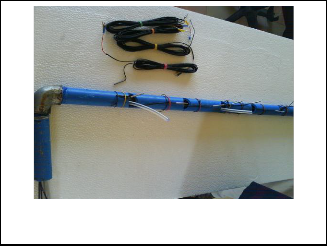
where ‘s’ is the salinity of the LCZ in g/Kg.
The effectiveness of the copper heat exchanger is taken as 0.9. The vertical distant (dncz) of the NCZ is 0.9. The water passing through the copper heat exchanger gets heated up due to the heat stored in the LCZ. For every time interval dt, the change in saline water temperature is taken as the sum of initial tem- perature (ambient temperature in the case of first iteration) and the temperature difference obtained from Eq.(1). Like that every time interval the change in temperature is calculated.
The thermal effectiveness, ηp, of solar pond can be defined as
the ratio of the useful energy stored to the amount of insola-
tion transmitted to the LCZ of the pond, both in the same pe-
riod, dt.
ηp = [ ( m Cp / dt ) * ( Tt+dt - Tt) ] / [ As Ig h(z)] (8)
In fig. 1 you can see the experimental set-up of solar-pond in- stalled in SRM University. It is made-up of mild steel and mounted on a concrete slab. The height of the pond is 0.95m and its diameter is 1.25m. The surface area exposed to the so- lar insolation is 1.23m2. In fig.2 you can see the arrangement of k-type thermocouples to measure the temperature of various zones of the solar-pond.
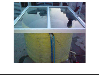
Fig. 2. Arrangement of K-type thermocouples to measure the temperature of various zones of solar-pond.
he above discussed mathematical model was coded in M-file to generate the temperature readings of the LCZ of the solar-pond at consecutive time intervals ‘dt’, the
code also generates the efficiency of the solar-pond at consecu- tive time intervals. With the help of M-file code we can find the temperatures of the LCZ and the thermal efficiency of the pond at consecutive time intervals for any solar pond of given dimensions. A physical model of LCZ of the solar-pond was built in simulink assuming the pond is perfectly insulated and only loss is because of the convection current created at the interphase of LCZ and NCZ. In fig.3 you can see the physical model of pond in simulink.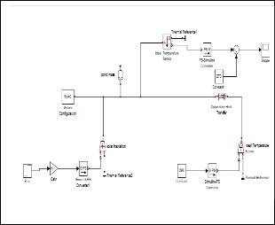
Fig. 1. Experimental set-up of solar-pond in SRM University
In fig.2. you can see the arrangement of 9 k-type thermo- couples adopted to measure the temperature of the solar pond at various zones.
Experiments were conducted with 50 g/Kg salinity concentra- tion in LCZ and the results obtained were compared with si- mulated results. The results from simulation were supporting the experimental results, there was not much variation.
Fig. 3. Physical model of solar-pond in simulink.
IJSER © 2012
The research paper published by IJSER journal is about Thermal modeling Of Solar Pond In Matlab 3
ISSN 2229-5518
The simulated results of solar-pond are for surface area 1.2m2, And dncz= 0.32m. Salt concentrations of 40g/Kg, 50g/Kg,
60g/Kg, and 70g/Kg were considered for the simulation. As
the salinity increases the temperature of the LCZ increases.
But 50g/Kg salt concentration was found to be most optimal
for the above pond. As the concentration of LCZ increases
there are chances of choking of pipes. The maximum experi-
mental temperature obtained was 45 οC between 12 noon to
2PM. The experimental values were little bit deviating from
the simulated values obtained in matlab. Following are the
simulated results obtained from the matlab.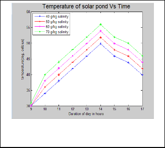
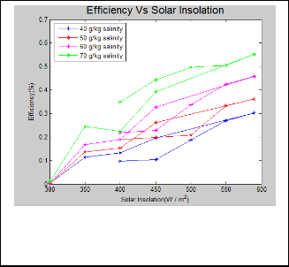
Fig. 6. Efficiency of the pond vs solar insolation, you can see as the insolation increases the efficiency increases, and as the insolation decreases the efficiency decreases. Higher efficiency can be obtained for higher salt concentration.
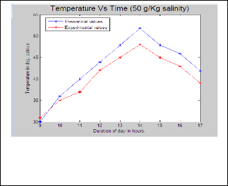
Fig. 4. Variation of temperature in LCZ for different salinities with duration of day. As the salinity increases the temperature of the LCZ increases.
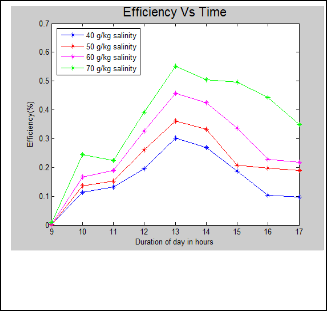
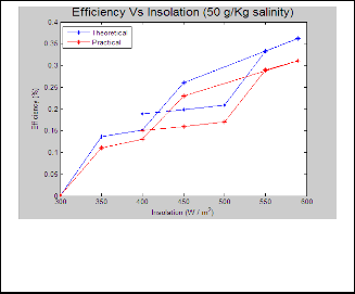
Fig. 7. Comparision of theoretical and practical values of LCZ temperatures with respect to time are shown here. 5 deg. Cel- cius difference was found between the theoretical and experi- mental values at the peak temperatures.
Fig. 5. Variation of efficiency of solar pond vs duration of day in hours. Efficiency of the pond increases for higher salinity. The efficiency of the pond is higher between 12 noon to 2 PM.
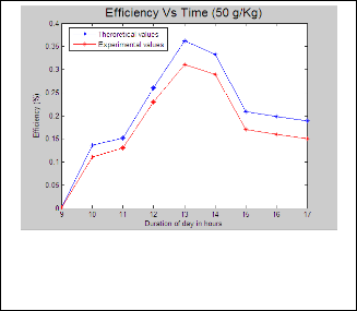
Fig. 8. Theoretical and experimental efficiencies of the pond at
50 g/Kg salinity are compared with respect to time. 0.05% differ- ence in the efficiencies was found at the peak insolation level.
IJSER © 2012
The research paper published by IJSER journal is about Thermal modeling Of Solar Pond In Matlab 4
ISSN 2229-5518
[6] Khashhan SA. Computer simulation of a solar pond, Msc thesis, JUST,
1993.
Fig. 9. Experimental and theoretical efficiencies of pond at 50 g/Kg salinity were compared with respect to time. 0.05 % differ- ence was found between the theoretical and experimental val- ues at the peak efficiencies.
With respect to the size of the solar-pond the above results were obtained. It was found that, as the salinity of the LCZ increases, the temperature of the LCZ and efficiency of the pond increases. But higher salt concentration in the LCZ may choke the pipe-lines. So from the simulated results in matlab
,we find that 50 g/Kg is the optimal salinity for the LCZ for our pond. The simulated results were not much deviating with the experimental results. Reliable results were obtained from the thermal modeling of pond in simulink. The solar-pond can be used as a pre-heater. Solar-pond can be integrated to still for increasing the efficiency of the still. Many pre-heating ap- plications of solar-pond and its portability, low space- requirement and its environmental friendliness make it more advantageous.
we sincerely thank Dr. M. Cherlathan for his overwhelming support, and encouragement given by him at every step of the project.
[1] Duffie JA, Beckman WA. Solar engineering of thermal processes. Ne- wark, (USA) : Wiley, 1991.
[2] Seebaluk D, Russol MS. A small-scale solar pond’s performance at
Reduit. PROSI Magazine, N 344, September 1997.
[3] Keren Y, Rubin H, Atkinson J, Priven M, Bemporad GA. Theoretical and experimental comparisions of conventional and advanced solar pond performances. Solar Energy 1993; 51(4) : 255-70.
[4] Newell TA, Boehm RF. Gradient zone constraints in a salt-gradient
solar pond. Solar Energy Engineering, 1982;104:285.
[5] Jabri AJI, Rasheed AM. An investigation of solar pond capability in providing space heating for resdental building in Baghdad/Iraq. JIMEC 97 1997;1:200-17.
IJSER © 2012