Inte rnatio nal Jo urnal o f Sc ie ntific & Eng inee ring Re se arc h Vo lume 3, Issue 3, Marc h -2012 1
ISS N 2229-5518
Thermal Performance Evolution of 2-D CFD Model of Natural Draft Wet Cooling Tower
Alok singh, S P S Rajput
—————————— ——————————
Cooling tow ers ar e heat r ej ection devices used to transfer waste heat to the atmospher e. Cooling tower s ar e an integr al part of many industr ial process. They ar e often
used in power generation plants to cool the condenser feed- water . In cooling tower the ambient air is used to cool
warm water coming fr om the condenser . Ther e ar e many cooling tow er designs or configurations. In dr y cooling tow ers the water is passed thr ough finned tubes forming a
heat exchanger so only sensible heat is transfer ed to the air . In w et cooling tow ers the water is sprayed dir ectly into the air so evaporation occur s and both latent heat and sensible heat ar e exchanged. Cooling tow ers can further be
categor ised into forced or natural draft tower s. For ced units
tend to be r elatively small str uctur es w her e the air flow is driven by fan.
_
Alok singh, Assista nt Professor, Depa rtment of Mechanical Engineering, Ma ulana Azad Na tiona l Institute Of Technology, Bhopa l (MP) India , E- ma il:- er_a loksingh@rediffmail.com
Dr.S.P.S. Ra jput, Associa te Professor, Depa rtment of Mecha nica l
Engineering, Maula na Azad Na tional Institute Of Technology, Bhopa l (MP)
India, E-ma il:- spsra jput@gma il.com
In a natur al dr aft cooling tower the air flow is generated by natur al convection only.
The draft is established by the density differ ence betw een the warm air inside the tow er and the cool dense ambient air outside the tow er . In a w et cooling tower , the water vapour inside the tow er contributes to the buoyancy and tow er draft. A further classification is betw een counter-flow and cr oss-flow cooling tow ers. In cr oss-flow configuration, the air flows at some angle to water flow wher eas in counter-flow the air flows in the opposite dir ection to water flow .
This study is concer ned with natural draft w et cooling tow ers (NDW CT) in counter-flow configuration. These structur es ar e most commonly found in power generation plants.
In a NDW CT in counter flow configuration. Ther e ar e thr ee heat and mass transfer zones,
1. spray zone
2. fill zone
3. r ain zone
IJSER © 2012 http :// www.ijser.org
Inte rnatio nal Jo urnal o f Sc ie ntific & Eng inee ring Re se arc h Vo lume 3, Issue 3, Marc h -2012 2
ISS N 2229-5518
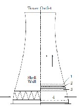
Figure 1. Natural draf t w et cooling tow er 1. Drif t eliminator 2. Nozzle 3. Fill 4. Water basin
The water is intr oduced into the tow er thr ough spray nozzles appr oximately 8-12m above the basin. The pr imary function of the spray zone is simply to distr ibute the water evenly acr oss the tower . The water passes thr ough a small spray zone as small fast moving dr oplets befor e enter ing the fill. Ther e ar e a range of fill types. Generally they tend to be either a splash bar fill type or film fill type. The splash bar type acts to br eak up water flow into smaller dr oplets with splash bars or other means. A film fill is a mor e modern design which forces the water to flow in film over closely packed par allel plates. This significantly incr eases the sur face ar ea for heat and mass transfer .
study to develop a tw o dimensional steady state simulation
of NDW CT.
model imagined in advance, because the possibilities in the subsequent steps depended on the composition of differ ent geometr ical shapes .Assumptions w er e made to take into account the main featur es of r eal constr uction.
2-D symmetry model is developed, fix the fill corr esponding to r eal arrangement.
Inlet and outlet space is cr eated at bottom and top of the tow er
Cooling tower shell is consider ed as a wall
with zer o thickness and its pr ofile is for med by curve by thr ee point including thr oat.
Assuming symmetrical thermal and flow field
in the model, only one half of the cooling
tow er is modeled with a symmetry boundary condition.
Fill depth 1 m
Tow er basin diameter 98 m
Fill base diameter 94 m
Tow er top diameter 68 m
Spr ay zone height 12 m
Water flow rate 15000 kg/s
Water inlet temperatur e 318 K
Ambient air temperatur e 298 K
Ambient air humidity 55 %
Ambient pr essur e 101 kPa
Inlet turbulence intensity 1 %
Design parameter s f or ref erence tow er
Differ ent parts is meshed with differ ent element sizing .
Fill zone must be fine meshed.
By using mapped face meshing mesh the model with appropr iate element sizing.
After mesh generation cr eate name of differ ent parts of cooling tow er .
The inner and outer sur face of the wall inside the model have identical shapes but ar e disconnected, so the mesh sizes on the two sides of the walls can be differ ent.
IJSER © 2012 http :// www.ijser.org
Inte rnatio nal Jo urnal o f Sc ie ntific & Eng inee ring Re se arc h Vo lume 3, Issue 3, Marc h -2012 3
ISS N 2229-5518
In cell zone sur face body is consider ed as fluid. The operating pr essur e is 101325 Pa in upstr eam from the center line of the cooling tow er . The gr avitational acceler ation is 9.81 m/s2 . Operating temper atur e is 288.16 K and oper ating density is 1.22 kg/m 3 enter ed.
Velocity inlet boundary condition is used to define the inlet velocity and other pr operties of air . Velocity magnitude of air takes normal to the boundary of inlet. Turbulence is taken as intensity and length scale. Thermal condition and species in mole fr action is defined.
Pr essur e out let is defined at out let of air . Other zone also
define likewise.
The governing equations for incompr essible steady fluid flow can be wr itten
in general form as:
∇ · (ρuφ – Ƭφ ∇φ ) = Sφ
wher e ρ is the air density (kg/m3), u is the fluid velocity
(m/s), φ is the flow variable (u, v,w , k, ε, T, ω) and Ƭφ is the diffusion coefficient for φ and Sφ the source term. These equations can be expanded into the individual momentum and transpor t equations w hich, together w ith the continuity equation give the Navier -Stokes Equations. These equations can be solved numerically enabling fluid flow to be
simulated forming the basis for CFD.
For all flows, FLUENT solves conservation equation for
mass and momentum. For flows involving heat transfer and compr essibility an additional equation ener gy conser vation is solved. For flows involving species mixin ,a species conser vation equation is solved.
The continuity equation for conservation of mass in
Cartesian coor dinates for tr ansient flow can be given as,
∂ρ / ∂t + ∇· (ρ→v) = Sm
wher e Sm is the mass sour ce term. The steady equation is
obtained by simply neglecting the transient ter ms, ∂/ ∂t ,
fr om the left hand side.
The equation for conser vation of momentum can be written
as,
∂/ ∂t (ρu i) + ∂/ ∂xj (ρu iuj) = − ∂p/ ∂xi + ∂/ ∂xj
[ μ ( ∂u i / ∂xj + ∂uj / ∂xi)] + S
wher e S is now a source term for momentum. The sour ce term for buoyancy
can be written as,
Sb = (ρ − ρref ) g
The transport equation for a scalar φ can be written as:
∂/∂t(ρφ ) +∂/ ∂xj(ρφuj) = ∂/ ∂xj [ρƬ (∂φ/∂xj)] + Sφ
Navier-Stokes equations r epr esent all the scales of fluid motion. Many flows in engineering ar e
highly turbulent and so r esolving all the scales explicitly using dir ect numer ical simulation is too computationally intensive, r equir ing very fine discr etisation of the above equations. Turbulence models ar e employed to r educe the computational wor k load by intr oducing simplifying assumptions and r epr esenting some of the scales of motion with additional equations.
The transport equations for the turbulence kinetic ener gy, k, and the rate
of dissipation, ε, ar e given as
∂/ ∂ t(ρk) + ∂/ ∂xi (ρ kui ) =∂/∂xj *(αk μeff) ∂k/ ∂xj ]
+ Gk + Gb − ρ ε + S k
∂/ ∂t (ρε) + ∂/ ∂xi (ρεu i) = ∂/ ∂xj *(α ε μeff)∂ ε/ ∂xj]
+ C1ε.ε/k (G k + C3εGb ) − C2ε ρ ε2/ k -Rε+Sε
![]()
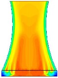
The air enter ing in to cooling tow er suddenly changes temper atur e due to contact of hot water coming out fr om nozzle. Highest temperatur e zone is near the axis of cooling tower . As the air flows up the temper atur e goes
IJSER © 2012 http :// www.ijser.org
Inte rnatio nal Jo urnal o f Sc ie ntific & Eng inee ring Re se arc h Vo lume 3, Issue 3, Marc h -2012 4
ISS N 2229-5518
dow n. Near wall of cooling tow er the air temperatur e is comparatively low.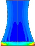
![]()

At inlet the pr essur e of air is maximum and gradually decr eases as the air flows up. Above the spray zone and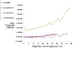
ar ound the axis up to some extent the pr essur e having very less some, time it is negative also. Some distance fr om wall the value of pr essur e is like constant thr ough- out the wall. Below the fill it is always higher than above the fill. Dynamic pr essur e is having higher value near the wall and lesser near the axis thor ough-out the cooling tow er height. Static pr essur e decr eases up to fill and than decr eases up to air outlet. Value of pr essur e coefficient is high at inlet and low at outlet.
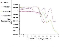
To find out the var ious pr oper ites of cooling tower ther e must be some line horizontzl w ith r efr ence to axis and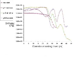
gr ound level.
S. NO. | Wind speed | Hor izontal line coor dinate (Diameter of cooling tow er ) | Line name | |
S. NO. | Wind speed | (X1 , Y1 ) | (X2 , Y2 ) | Line name |
1 | 2 m/s | (0, 6 ) (49, 6 ) | Y=6 , at rain zone | |
2 | 2 m/s | (0, 13) (46, 13) | Y=13, above spray zone | |
3 | 2 m/s | (0, 65) (36, 65) | Y=65, at middle |
Thr ee line dr awn hor izontally at rain zone, above spr ay zone and at middle of the cooling tow er to find out the various thermal pr oper ties of cooling tower .
IJSER © 2012 http :// www.ijser.org
Inte rnatio nal Jo urnal o f Sc ie ntific & Eng inee ring Re se arc h Vo lume 3, Issue 3, Marc h -2012 5
ISS N 2229-5518
Nomenclature Cp specific heat (j /kg K) g gravitational acceler ation (m/s 2 ) G mass flow rate per unit ar ea (kg/s/m2 ) k turbulence kinetic ener gy (m2 /s2 ) R univer sal gas constant (N.m/kmol.K)
S sour ce term U, v velocity component (m/s)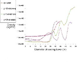
turbulence kinetic ener gy dissipation rate
(m2 /s3 ) Ƭ diffusion coefficient (kg/ms) μ viscosity (kg/ms) ρ air density (kg/m3 ) α kinetic ener gy coefficient
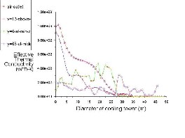
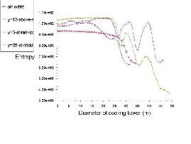
The simulation of multi phase steady state flow inside a natur al dr aft cooling tower has been conducted using CFD code “FLUENT 12”. Thermal parameter has been find out in various positions inside cooling tow er along the diameter . Air temper atur e var ies fluently above and below the fill because maximum heat transfer take place in fill zone as compar e to spray zone and rain zone. At outl et air temperatur e changes ar ound 5% near axis, wher e at its change near the w all is only 3%. Random change of
pr essur e occur s below the fill, near w all its value almost
zer o. Enthalpy and entr opy having descending values
towar ds wall fr om axis.
1. Klo ppe rs, J.C. and Kroge r, D.G. A c ritic al cooling towe r
pe rfo rmance ev aluatio n. In 12th IARH Sy mpo sium in Coo ling
To we r and He at Exc hange rs, UTS, Sy dney , Australia, 11 -14
Nove mbe r 2001.
2. Gan, G., Riffat, S ., S hao , L. and Do he rty , P. Applic atio n o f CFD to c lose d-we t coo ling to we rs. Applie d The rmal Eng inee ring, 21:79–92, 2001.
3. Fo urnie r, Y. and Boye r, V. Improve me nts to the N3S -AERO he at
e xc hange r and cooling towe r simulatio n co de. In 12th IARH
Sy mpo sium in Coo ling To we r and He at Exc hange rs, page s 339–
350, UTS, Sy dney, Australia, 11 -14 Nove mbe r 2001.
4. De V illie rs, E. and Kr¨oge r, D.G. Inle t lo sses in co unte rflo w
we tcoo ling to we rs. Jo urnal o f Eng inee ring fo r Gas Turbine s and
Po we r, 123:460–464, 2001.
5. Pe truc hik, A.I., Solo dukhin, A.D. and Fise nko, S.P. S imulatio n o f
cooling o f wate r dro ple t and film flo ws in large natural we t cooling to we rs. Jo urnal o f Eng inee ring Phy sics and
The rmo physic s, 74(1):62–68, 2001.
6. Hasan, A. and Gan, G. Simplific atio n o f analy tic al mo de ls and inco rpo ratio n with CFD fo r the pe rfo rmance pre dic atio n o f
c lose d-we t coo ling to we rs. Inte rnatio nal Jo urnal o f Ene rgy
Re se arc h, 26:1161 – 1174, 2002.
7. Fise nko, S.P., Pe truc hik, A.I. and So lo dukhin, A.D. Ev apo rative
cooling o f wate r in a natural draft coo ling to we r. Inte rnatio nal
Jo urnal o f He at and Mass Transfe r, 45:4683 –4694, 2002.
8. Hawlade r, M.N.A and Liu, B.M. Nume ric al study o f the the rmal
hy draulic pe rfo rmance o f ev apo rative natural draft coo ling to we rs. Ap plie d The rmal Eng ine e ring , 22:41 –59, 2002.
9. M. Le mo uari, M. Bo umaza, Expe rime ntal study o f the air/wate r he at transfe r by direc tco ntac t in a co lumn pac ke d with v e rtic al g rids – applic atio n to the wate r cooling, in: Procee ding 11th
Inte rnatio nal Mee ting o n He at Transfe r (JITH2003), vo l. 2, 2003, pp. 457–464.
IJSER © 2012 http :// www.ijser.org
Inte rnatio nal Jo urnal o f Sc ie ntific & Eng inee ring Re se arc h Vo lume 3, Issue 3, Marc h -2012 6
ISS N 2229-5518
10. Klo ppe rs, J.C. and Kr¨oge r, D.G. Lo ss coe ffic ie nt co rre latio n fo r we t-coo ling to we r fills. Applie d The rmal Eng inee ring , 23:2201 –
2211, 2003.
11. Klo ppe rs, J.C. A Critic al Ev aluatio n and Re fine me nt o f the Pe rfo r
manc e o f We t-Coo ling To we rs. PhD the sis, Unive rsity o f
S te lle nbosc h, S te lle nbosc h, South Afric a, 2003.
12. S iro k, B., Blago jev ic, B., Nov ak, M., Hoc hev ar, M. and Je re , F.
Ene rgy and mass transfe r phe no me na in natural draft coo ling to we rs. He at Transfe r Eng inee ring , 24(3):66–75, 2003.
13. Kröge r, D.G., Air-coo le d He at Exhang e rs and Coo ling Towe rs: The rmal-flo w Pe rfo rmance Ev aluatio n and Desig n, Pe nwe ll
Co rp., Tulsa, Oklaho ma, 2004.
14. Fise nko, S.P., Brin, A.A. and Pe truc hik, A.I. Ev apo rativ e coo ling o f wate r in a mec hanic al draft coo ling to we r. Inte rnatio nal
Jo urnal o f He at and Mass Transfe r, 47(1):165–177, 2004.
15. Klo ppe rs, J.C and Kröge r, D.G., Coo ling To we r Pe rfo rmance : A Critic al Ev aluatio n o f the Me rke l Assumptio ns , R & D Jo urnal, Vo l. 20, No 1, pp. 24 - 29, 2004.
16. Al-Wake d, R. and Be hnia, M. The pe rfo rmance o f natural draft
dry coo ling to we rs unde r c ro ss-wind: CFD study . Inte rnatio nal
Jo urnal o f Ene rgy Re se arc h, 28:147–161, 2004.
17. J.R. Khan, B.A. Qureshi, S.M. Zubair, A co mpre he nsive de sig n
and pe rfo rmanc e ev aluatio n study o f co unte r flo w we t cooling to we rs, Inte rnatio nal Jo urnal o f Re frige ratio n 27 (2004) 914–923.
18. Al-Wake d, R. and Be hnia, M. The e ffec t o f windbre ak walls e ffec t o n the rmal pe rfo rmance o f natural draft dry coo ling to we rs. He at Transfe r Eng ine e ring , 26(8):50–62, 2005.
19. Klo ppe rs, J.C. and Kroge r, D.G. A c ritic al inve stig atio n into the he at and mass transfe r analy sis o f
co unte rflow we t-coo ling to we rs. Inte rnatio nal Jo urnal o f He at and Mass Transfe r, 48:765–777, 2005.
20. Klo ppe rs, J.C. and Kr¨oge r, D.G. Re fine me nt o f the transfe r
coe ffic ie nt co rre latio n o f we t coo ling to we r fills. He at transfe r e ng inee ring , 26:35–41, 2005.
21. Al-Wake d, R. Deve lo pme nt o f Pe rfo rmance -Improv ing S truc ture s fo r Powe rS tatio n Cooling To we rs. PhD the sis, Unive rsity o f Ne w So uth Wale s, Sy dney, Australia, 2005.
22. Klo ppe rs, J.C. and Kr¨oge r, D.G. The Le wis fac to r and its
influe nc e o n the pe rfo rmance pre dic tio n o f we t-coo ling to we rs. Inte rna-tio nal Jo urnal o f The rmal Sc ie nce s, 44:879 –884, 2005.
23. Klo ppe rs, J.C. and Kr¨oge r, D.G. Influe nce o f te mpe rature
inve rsio ns o n we t-coo ling to we r pe rfo rmance . Applie d The rmal
Eng inee ring, 25:1325–1336, 2005.
24. S arke r, M. M. A., Kim, E. P., Moo n, C. G. and Yoo n, J. I.; “The rmal
Pe rfo rmance Charac te ristic s o f
Close d-We t Cooling To we r”, J. Ko re an
Soc ie ty fo r Powe r Syste m Eng inee ring, Vo l.
9, No. 2 (2005), pp. 88 -92.
25. Williamso n, N., Be hnia, M. and Armfie ld, S . Co mpariso n o f a 2D
axisy mme tric CFD mo de l o f a natural draft we t coo ling to we r and a 1D mo de l, Inte rnatio nal Jo urnal o f He at and Mass Transfe r 51 (2008) 2227-2236.
26. Theo ry g uide o f” Ansys 13” 2010.
IJSER © 2012 http :// www.ijser.org