International Journal of Scientific & Engineering Research, Volume 6, Issue 2, February-2015 133
ISSN 2229-5518
Theoretical and Experimental Study for Hybrid
Journal Bearing
Lijesh K.P., Harish Hirani, Samanta P.
Abstract— Journal bearings are well known for their lowest wear rate and high damping coefficients under fully developed hydrodynamic lubrication mechanism. However, metal-metal contact at start/stop and low speed condition, causing bearing wear and excessive power loss, are major disadvantages of hydrodynamic bearing. Therefore, a concept of hybrid (hydrodynamic-permanent magnetic) bearing for the radial applied load has been developed. In such bearings the static load is taken by magnetic bearing and dynamic load by hydrodynamic bearing. However, due to the unstable nature of passive magnetic bearings and larger axial thrust compared to radial thrust emphasis for the requirement of extra subassembly and proper alignment compared to conventional bearings test setup. In the present work, using 3D Coulombian model, the radial and axial forces of a passive magnetic bearing for the given dimension having different arc length of the top stator magnet have been analyzed. To reduce the unstable force, the required axial offset was estimated. After obtaining the required configuration from the theoretical results, the hybrid bearing was developed. Experiments were performed on the preliminary developed experimental setup and the challenges faced for development of setup and problems faced after performing the experiment have been reported. A detailed investigation was carried out to overcome the problems and various solutions have been provided.
Index Terms— Passive Magnetic Bearing, Hydrodynamic bearing, Hybrid bearing, Radial load, Axial load, Axial offset, Coulombian model
—————————— ——————————
1 INTRODUCTION
IFE Life of well-designed machine components, in rela- tive motion, is decided by wear rate occurred in running
augment the hydrodynamic bearing for satisfactory opera- tion at low speeds.
conditions. On comparing the data related to wear coef- ficients collected under different mechanical contact condi- tions, as shown in Table1 [1], one finds lowest wear rate in the hydrodynamic mechanism. The lowest value of friction coefficient under fully developed hydrodynamic conditions, as shown in Table2 [2], is an additional advantage of hydro- dynamic journal bearing. Rolling contact bearing [3], a com- petitor of hydrodynamic bearings [4-5], has a finite life for a given load and speed condition. Further low damping, noisy
TABLE 1
WEAR RATE [1]
10
-10
10 -
-7
operations, and high contact stresses make rolling element bearings inferior to hydrodynamic journal bearing. Very- low/high values of load and high-speed cause significant reduction in rolling-bearing life. However, the major disad- vantage of hydrodynamic bearing is its inability to make hydrodynamic-lubricant-film at start, stop and low speed operations [6-7], which brings journal bearing under mixed/boundary lubrication conditions [8-9]. Table 2 indi- cates a reduction in the coefficient of friction from 0.25 (dur- ing start/stop operation) to 0.001 (under fully developed hydrodynamic lubrication). In other words, if a system of rotor bearing system requires X horse power for normal op- eration, then it needs 250X horsepower during start-up op- eration. This requirement of huge horsepower just for start- ing purpose is objectionable in the present competitive world, where minimization of power loss, weight and cost are the main objective functions. Therefore, there is a need to
————————————————
• Lijesh K.P. PhD, Mechanical Department. Indian Institute Technology
Delhi, India, E-mail: lijesh_mech@yahoo.co.in
• Harish Hirani, Professor Mechanical Department, Indian Institute Tech-
nology Delhi, New Delhi, E-mail: hirani@mech.iitd.ac.in
• P. Samanta, Scientist, Surface Engineering and Tribology, CMERI Dur-
gapur, India, E-mail: p_samanta@cmeri.res.in
TABLE 2
DIFFERENT FRICTION COEFFICIENTS [2]
Type | Hydro- dynamic Contact | Dry Bearing | Semi lub- ricant bearing | Roll- ing ele- ment Bear- ing |
Start up friction Co- efficient | 0.25 | 0.15 | 0.1 | 0.05 |
Running friction Co- efficient | 0.001 | 0.1 | 0.05 | 0.05- 0.001 |
As an alternative, hydrostatic bearing is the best choice for its minimum start-up friction (0.0001), high stiffness and high load carrying capacity at low speeds. Hydrostatic bear- ings, however, have the disadvantage of requiring complex lubrication system consisting of high pressure subsystem, filtering subsystem, feedback control system, and complex geometry. Such a system requires high initial and running costs, and occupies space. Another alternative is active mag- netic bearings [10-11] that provide lubricant free, adjustable damping and stiffness characteristics in all directions, and allow high-speed relative motion. However, the active mag-
IJSER © 2015 http://www.ijser.org
International Journal of Scientific & Engineering Research, Volume 6, Issue 2, February-2015 134
ISSN 2229-5518
netic bearing incurs high cost, has complicated structure, and relatively low (5-15 %) capacity compared to hydrody- namic bearing [11].
One can think of hybrid bearings such as: hydrodynamic- hydrostatic, hydrodynamic-active-magnetic or hydrodynam- ic-permanent-magnetic bearings. Hydrodynamic-hydrostatic bearing is an old concept and has been used in almost every journal-bearing configuration. Generally hydrodynamic bearing is made with a lubricant supply groove, and the lub- ricant is fed at a pressure above the atmospheric pressure. Level of supply pressure decides the hydrostatic action. However, in many cases, supply pressure pump is linked with shaft (such as in internal combustion engines), support- ed on the bearing. Therefore, supply pressure cannot be achieved at the start/stop of shaft-rotation. So, first two hy- brid concepts (hydrodynamic-hydrostatic and hydrodynam- ic-active-magnetic), which are complicated in structure, and having expensive hydraulic systems, sensors, power ampli- fiers and controllers, cannot be justified for ordinary indus- trial applications. The best solution is the use of repulsive
equation (1).

dF13 = σ1σ 2r1dβdr1r2dr2dα
4πµ0 r13

r13
(1)
type passive magnetic levitation [12-13] in the hydrodynam- ic bearing to extract the advantages of magnetic bearing at low speeds for reducing the start-up friction and the ad- vantages of hydrodynamic bearing at high speeds which will be attractive in commercial applications for their low cost, simplicity in structure and no metal-to-metal contact.
In the present case, the hybrid bearing is made of perma- nent magnets to develop repulsions between magnets and lubricant is supplied to develop hydrodynamic action be- tween relatively moving permanent magnets. The setup for testing hydrodynamic action is well known, however club- bing testing of repulsive action between magnets requires
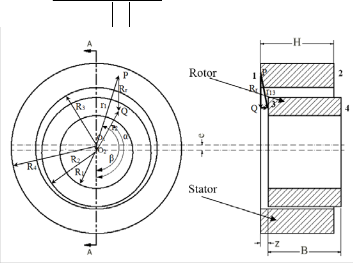
Fig. 1 Orthographic views of Magnetic bearing
Where r1 is the position vector between O1 and P; r2 is po- sition vecor between O2 and Q; r12 is the position vector be- tween P and Q; and σ1 , σ2 are the surface density of rotor and stator magnet respectively. From figure 1, the position


vector between P and Q ( r13 ) can be expressed as r13 = e + r1 + r2 + z . The force in y direction (load due to
gravity) is given by:
σ σ r dβdr r dr dα
thorough analysis. In the case of passive magnetic bearing, there is a very strong coupling between axial and radial stiffness of cylindrical magnets [14]. In other words, radial permanent-magnet bearing, designed to support radial load, will be unstable in axial direction. To assure stability of radi-


dF y13 = dF13 . j = 1 2 1 1 2 2 r13 .j
4πµ0  r13
r13 


Where: r13 .i = (r2 sin α + r1 sin β ), r13 .j = e + r2 cosα − r1 cos β
(2)


al bearing made of permanent-magnets requires a separate


( )2


( )2
1 / 2
( )2
arrangement/modification in the test setup.
Using 3D Coulombian [15-18] model the radial and axial
r13 = e + r2 cos α − r1 cos β
+ r2 sin α + r1 sin β
+ L + z − H
loads were studied. Based on the estimated results, a test setup was fabricated for the hybrid bearing incorporating the selected configuration of magnetic bearing. The prob-
The force in y and z, generated between faces 1 and 3 can
be calculated by integrating equation 3(a-b) along the end
faces of the magnet.
lems faced during and after the development of test set up
θ4 R4θ2 R2


θ4 R4θ2 R2
σ σ e + r cos α − r cos β
Fy =
dF13 . j = 1 2
2 1 r dr dβr dr dα (3(a))
have been presented and the solutions to those problems
13 ∫ ∫ ∫ ∫
θ3 R3 θ1 R1


4πµ0 ∫ ∫ ∫ ∫ (e + r cos α − r cos β )2
1 / 2 1 1 2 2
have been discussed.


+ (r sin α + r sin β )2 + (L + z − H )2
2 1
2 MODELING OF PERMANENT MAGNET
A magnetic beairng, made of two cylinderical magents,
θ 4 R4 θ 2 R2

13 13
1 2
θ 4 R4 θ 2 R2
( )
1 1 2 2
(3(b))
Fz =
∫ ∫ ∫ ∫
dF .k = σ σ


∫ ∫ ∫ ∫
L + z − H
1 / 2
r dr dβr dr dα
has been depicted in figure 1. Inner and outer radii of rotor
θ 3 R3 θ 1 R1
4πµ0 θ R θ R (e + r cosα − r cos β )2
have been symbolized as ‘R1’ and ‘R2’ respectively. Simi- lalry, the inner and outer radii of stator are depicted as ‘R3’ and ‘R4’ respectively. The repulsive force, generated by the stator magnet on the rotor magnet, comes from the interac- tion between the charges located on the surfaces of magnetic poles (1,2,3,4 shown in figure 6). The net force can be esti- mated by summing the force between faces 1-3, 1- 4, 2-3 and
2-4. The elemetary force between surfaces 1-3 is given in


+ (r2 sinα + r sin β ) + (L + z − H )2
2
1


Similarly total force in y and z directions developed be- tween faces 1-4 ( F14 ), faces 2-3 ( F23 ) and faces 2-4 ( F 24 )
by the rotor magnet on the stator magnet is given by equa-
tion 4(a) and 4(b) respectively.
IJSER © 2015 http://www.ijser.org
International Journal of Scientific & Engineering Research, Volume 6, Issue 2, February-2015 135
ISSN 2229-5518
2π R4 2π R2 1 1


σ σ −

− 1 +
1

MENSIONS OF THE MAGNETIC RINGS.
Fy == 1 2 ∫ ∫ ∫ ∫ r13
r23
r14
r24 r1dr1dβr2dr2dα
(4(c))
4πµ0


0 R3 0 R1 (e + r cosα − r cos β ) 5
2π R4 2π R2 ( L − H + z ) − ( L + z ) − ( H − z ) + ( z )


σ σ
Fz == 1 2 ∫ ∫ ∫ ∫
r13
r23
r14
r24 r1dr1dβr2dr2dα (4(b))
4πµ0


0 R3 0 R1 (e + r cosα − r cos β )
Where:


r = (e + r cosα − r cos β )2 + (r

sinα + r sin β )2 + (L + z )2
1 / 2
200
150
Radial
Axial
23 2 1 2 1
1 / 2
100


r = (e + r cosα − r cos β )2 + (r

sinα + r sin β )2 + (H − z )2 50
14 2 1 2 1
1 / 2 0


r = (e + r cosα − r cos β )2 + (r

sinα + r sin β )2 + (z )2
24 2 1 2 1
15
-50 10
Radial
Axial
The rotor magnet in the present work is a full ring magnet i.e. θ1 =0 and θ2 =1800 while the value of θ3 and θ4 depends upon the position of the stator sector magnet. The final equation for sector magnet is given by:
-100
-150
5
0
-5
-10
-15
-20
-3 -2 -1 0 1 2 3 4 5
Axial offset (m) x 10-4
θ 4 R4 2π R2 1 1
σ σ −

− 1 +
1

-200
-0.015 -0.01 -0.005 0 0.005 0.01 0.015


Fy == 1 2 ∫ ∫ ∫ ∫ r13
r23
r14
r24 r1dr1dβr2dr2dα (5(a))
Axial offset (m)
4πµ0


θ3 R3 0 R1 (e + r cos α − r cos β )
( L − H + z ) − ( L + z )
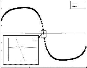
Fig 2 Magnetic forces for different axial offset at eccentricity ratio 0.99


σ σ θ 4 R4 2π R2
r13
r23
Fz == 1 2 ∫ ∫ ∫ ∫
r1dr1dβr2dr2dα
(5(b))
4πµ0
θ3 R3 0 R1 −

( H − z ) +
r14
( z )

r24
Each integrating terms in equation 5(a) and 5(b) is solved
using Gaussian Quadrature numerical integration method in
MATLAB software.
2.1 Results and Discussion
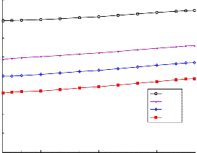
To provide hydrodynamic action, the clearance between the rotor and stator magnets is kept as 25µm. In the present work the applied load is set a 80N in the form of disk and loading was applied on two numbers of passive magnetic bearings. Therefore the sing magnetic bearing will be designed for 40N. The dimensions of the magnet considered for the present case is tabulated in table 1. The axial and radial force estimated for the full ring magnet is plotted in figure 2. From this figure it can be observed that the due to less clearance the radial load is only 3N and axial load in 150N which is less than the applied load. However the radial load can be increased and unstable axial load can be reduced by reducing the arc length of the stator magnets in the top side. In the present study magnetic bearing with four different top arc length of stator (i) 00, (ii) 300, (iii) 450 and (iv) 600 (as shown in figure 3) is analyzed.
TABLE 3
PROPERTIES OF THE PERMANENT MAGNETIC MATERIAL AND DI-
(a) 00 (b) 300
(c) 450 (d) 600
Fig.4 Different arrangement of magnetic bearing considered for analysis
IJSER © 2015 http://www.ijser.org
International Journal of Scientific & Engineering Research, Volume 6, Issue 2, February-2015 136
ISSN 2229-5518
80
80
70
60
60
40
50
20 40
0 30
20
-20
10
0 deg
30 deg
45 deg
60 deg
-40
-0.015 -0.01 -0.005 0 0.005 0.01 0.015
Axial Offset(m)
0
-1 -0.8 -0.6 -0.4 -0.2 0 0.2 0.4 0.6 0.8 1
(a) Radial force
(a) R
Eccentricity Ratio
Fig.5
120
90
0 deg
30 deg
Radial load for different eccentricity for different arrangement
48
50
10
-30
45 deg
60 deg
47 0
0.0005
46 0.001
45
44
-70 43
-110
-150
-0.015 -0.01 -0.005 0 0.005 0.01 0.015
Axial offset (m)
(b) Axial force
Fig 4 Magnetic forces for non-uniform magnetic field with different ec-
centricity
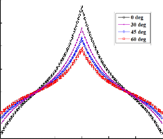
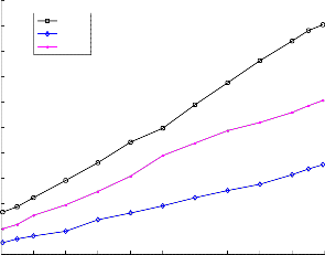
The radial and axial load carrying capacity of different ar-
rangement is plotted in figure 4(a) and 4(b) respectively. From these figures following conclusion were made:
(i) Radial load decreases with the increase in arc length of top stator magnet while increases the axial unstable force.
(ii) The radial magnet load carrying capacity is maximum at the zero offset and decreases with axial offset while axial load carrying capacity is zero at the center and maxi- mum at an axial offset of 0.005m. However, any small deviation from the zero offset will increase the axial load and will lead to bearing failure.
(iii) For half ring magnet the radial load carrying capacity is
maximum and axial force is minimum, but it can be not- ed that for half ring magnet the value of radial load and axial load is almost equal.
42
41
40
39
38
-1 -0.8 -0.6 -0.4 -0.2 0 0.2 0.4 0.6 0.8 1
Eccentricity ratio
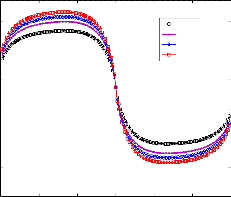
Fig.6 Radial load at different eccentricity for arrangement with 450 top stator magnet for different axial offset
In the present work the applied load is 80N on two bearing, while the load estimated for half ring magnetic bearing is 150N (by two bearing) which is higher than the applied load. In fig- ure 4 the eccentricity ratio was selected to be maximum (0.99), it required to estimate the load carrying capacity at minimum eccentricity so that to whether rotor will hit the top stator. Fig- ure 5 shows the plot for radial load carrying capacity for dif- ferent arrangement at different eccentricity ratio. From this figure it can be observed that for arrangement 00, 300 and 450 the load at the minimum eccentricity is greater than the ap- plied load hence the rotor will be hitting the top stator magnet. However for the magnetic arrangement with 450, the load car- rying capacity can be reduced by providing some axial offset. This offset can be provided in the motor side so that the axial disturbance can be avoided. The radial load for different axial offset is shown in figure 6. From this figure it can be observed that with axial offset of 0.0005m the load carrying capacity reaches the range of the applied load. Since providing an axial offset of exactly 0.0005m is difficult, in the present work an
IJSER © 2015 http://www.ijser.org
International Journal of Scientific & Engineering Research, Volume 6, Issue 2, February-2015 137
ISSN 2229-5518
axial offset in the range of 0.0005mm to 1mm is set. In the fol- lowing section the discussion of setup development with the obtained arc length and axial offset is performed.
3 DEVELOPMENT OF HYBRID BEARING TEST SETUP
The initial test setup designed on the basis of the simula- tion results is shown in the Fig. The setup was developed to experience the behavior of the proposed hybrid bearing under various lubrication mechanisms such as boundary, mixed and hydrodynamic-lubrication by varying the rotor speed ranging between 100 to 6000 rpm.
This setup consists of a 1HP 3-phase motor and the cou-
pling to connect the stainless steel shaft and motor, two hybrid
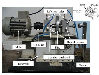
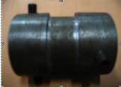
bearing and lubrication system. A disk of mass 8kg has been mounted on the shaft at the center of hybrid bearing. NdFeB material have been used as a bushing for journal bearing and cylindrical magnets of same material have been mounted on the shaft. Details have been shown in figure 7. Liners of the aluminum rings have been used because aluminum is non- magnetic material and it will not be attracted by the magnets. All the liners, magnets and aluminum, have been placed on the housing tightly to form a complete circular bushing. The oil is supplied to the hybrid bearing clearance is fed by gravity through the oil hole located at 40o from load line as shown in Fig 7 by means of a flexible pipe from the oil tank. After first installation of setup a number of unforeseen problems came across, which were difficult to outline at the designed stage. These problems are categorized in (i) Axial thrust, (ii) Cou- pling, and (iii) Bearing arrangement. All these problems with probable solutions are detailed as follows.
Fig-7 Hybrid Bearing test setup
3.1 Axial Thrust
(i) To provide the axial thrust, three different arrangements of providing thrust bearings were applied.
(ii) In the first arrangement a thrust bearing mounted a plate was set as shown in figure 8. With this modification rota- tional speed was increased to approximately 800 rpm. At higher rpm, thrust bearing was unable to locate the shaft
and shaft was slipped away from motor coupling to bear- ing housing as shown in figure 6(b).
(a) Thrust Bearing
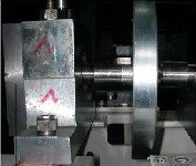
(b) Slippage of shaft
Fig. 8 Thrust bearing failure
(iii) Another effort had been taken to reduce the axial force by using the axial thrust force of the powerful magnet as shown in figure 7. By this change, speed had been reached up to 1000rpm.
(iv) In the third arrangement based on the simulation result
an axial offset of 0.001 was provided and observed that
the stator magnets and system became more stable than before. It was able to reach up to speed of 1700 rpm. However still the problem persisted and further investi- gation was performed by changing flexible jaw coupling to rigid coupling or semi rigid (spiral) coupling.
3.2 Coupling
To deal with axial thrust force induced by permanent magnetic bearing, jaw type coupling was changed to rigid coupling (shown in figure 9(a)). Rigid coupling had created problem of misalignment and sharing the load. To eliminate this ambiguity a semi-rigid (aluminum spiral) coupling as shown in figure 9(b) was used. This spiral coupling was able to bear the misalignment and allow 6000 rpm rotational speed of shaft. However, at higher speed wobbling of shaft was ob- served. This has raised the question on formation of hydrody- namic action, which is explained in the next subheading.
IJSER © 2015 http://www.ijser.org
International Journal of Scientific & Engineering Research, Volume 6, Issue 2, February-2015 138
ISSN 2229-5518
4 CONCLUSION
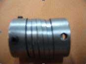
(a) Rigid Coupling
(b) Spiral Coupling
Fig. 9 Couplings
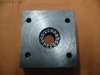
3.3 Bearing Arrangement
Based on the simulation the magnetic bearing made by us- ing 1800 and 450 magnets mounted on the aluminum ring as shown in figure 10(a). The wobbling of the rotor might have occurred due to the discontinuity formed during the assembly of the magnets in the aluminum ring. To reduce the problem of wobbling at higher speed and form a continuous smooth inner surface, aluminum ring along with magnets were coated with Teflon as shown in figure 10(b) and then again magnetized. With all these changes setup was working satisfactorily at both low and high speed.
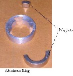
(a) Magnetic Bearing

(b) Hybrid Bearing
Fig. 10 Magnetic and hybrid bearing
.
Different configurations of magnetic bearing were proposed and detailed theoretical study on those configurations using
3D Coulombian model were performed. Following conclu- sions can be made from the theoretical study
(i)Radial load decreases and axial unstable force increases with the increase in arc length of top stator magnet.
(ii)The maximum radial load and the minimum axial load
occur at the zero offset.
(iii)For half ring magnet the radial load carrying capacity is
the maximum and axial force is the minimum
(iv)An experimental setup for hybrid was developed. The
first few experiments showed unsatisfactory performance and on investigation it was found that providing suffi- cient axial offset and usage of spiral coupling can reduce majority of the problems. By providing Teflon coating to the hybrid bearing configuration eliminated the wobbling of the rotor.
ACKNOWLEDGMENT
This research was supported by Council of Scientific and
Industrial Research, New Delhi, India, Grant No.
70(0073)/2013/EMR-II.
References
[1] M.B.Peterson and W.O.Winer, “Wear Control Handbook,” ASME, New
York, pp..443, 1980 .
[2] M. M. Khonsari and E. R. Booser, “Applied Tribology, Bearing Design and
Lubrication,” John Wiley & Sons, Inc. (2001)
[3] H. Hirani, “Root cause failure analysis of outer ring fracture of four row cylindrical roller bearing,” Tribology Transactions, vol. 52, no. 2, pp. 180-190,
2009.
[4] H. Hirani, and P. Samanta, “Hybrid (Hydrodynamic + Permanent Magnet- ic) Journal Bearings,” Proc. Institute Mech. Engineers., Part J, Journal of Engi- neering Tribology, vol. 221, no. 8, pp. 881-891, 2007.
[5] H Hirani, “Multiobjective optimization of journal bearing using mass con- serving and genetic algorithms,” Proc. Institute Mech. Engineers., Part J, Jour- nal of Engineering Tribology, vol. 219, no. 3, pp. 235-248, 2005.
[6] H Hirani and M Verma, "Tribological study of elastomeric bearings of marine shaft system,” Tribology International, vol. 42, no. 2, pp. 378-390,
,2009.
[7] H Hirani, K Athre and S Biswas,"Dynamic Analysis of Engine Bearings", International Journal of Rotating Machinery,” vol. 5, no. 4, pp. 283-293, 1999.
[8] S.M. Muzzakir, K.P. Lijesh, and H. Hirani, “Tribological Failure Analysis of a Heavily-Loaded Slow Speed Hybrid Journal Bearing,” Engineering Failure Analysis, vol. 40, pp. 97–113, 2014.
[9] S M Muzzakir, K P Lijesh, H Hirani, and G D Thakre, “Effect of Cylindricity on the Tribological Performance of Heavily-Loaded Slow Speed Journal Bearing,” Proc. Institute Mech. Engineers., Part J, Journal of Engineering Tribolo- gy, vol. 229, no. 2, pp.178-195, 2015.
[10] K. P. Lijesh, and H. Hirani, “Optimization of Eight Pole Radial Active Mag-
netic Bearing,” ASME, Journal of Tribology, vol. 137, no. 2, (7 pages), 2015.
IJSER © 2015 http://www.ijser.org
International Journal of Scientific & Engineering Research, Volume 6, Issue 2, February-2015 139
ISSN 2229-5518
[11] S. Shankar, S. Sandeep and H. Hirani, “Active magnetic bearing: a theoreti- cal and experimental study,” Ind.J. Tribol., vol. 1, pp.15–25, 2006.
[12] K. P. Lijesh, and H. Hirani, “Development of Analytical Equations for De- sign and Optimization of Axially Polarized Radial Passive Magnetic Bear- ing,” ASME, Journal of Tribology, vol. 137, no. 1, (9 pages), 2015.
[13] P. Samanta, and H. Hirani, “Magnetic Bearing Configurations: Theoretical and Experimental Studies,” IEEE Transactions on Magnetics, vol. 44, no. 2, pp. 292-300, 2008.
[14] S. Earnshaw, “On the nature of molecular forces which regulate the consti- tution of luminiferous ether,” Trans. Cambridge Phil. Soc, vol. 7, pp. 97–112,
1839.
[15] K. P. Lijesh and H. Hirani, “Stiffness and Damping Coefficients for Rubber mounted Hybrid Bearing,” Lubrication Science, vol. 26, no. 5, pp.301-314,
2014.
[16] H. Hirani and P. Samanta, "Hybrid (Hydrodynamic + Permanent Magnet- ic) Journal Bearings," Proc. Institute Mech. Engineers., Part J, Journal of Engi- neering Tribology, vol. 221, no.8, pp. 881-891, 2007,.
[17] P. Samanta, and H. Hirani, “A Simplified Optimization Approach for
Permanent Magnetic Journal Bearing,” Ind.J. Tribol, 2007.
[18] K. P. Lijesh, and H. Hirani, “The Performance of Hybrid Journal Bearing under Extreme Operating Conditions,”IJCET, vol. 5, no. 1, pp. 277-282,
2015.
IJSER © 2015 http://www.ijser.org