The research paper published by IJSER journal is about The Power Saving Low Cost Rotating 8 Led Information Display 1
ISSN 2229-5518
The Power Saving Low Cost Rotating 8 Led
Information Display
Sheikh Rafik Manihar
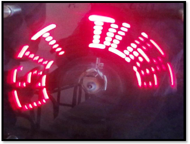
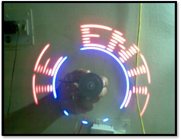
Abstract- This paper explains the project which is a special kind of circular rotating 8 LED display. W ith the help some mechanical assembly , LED count, hardware requirement, and hence overall cost is cut to very affordable price and power is also saved. Also, maintenan ce and repairing of the display is so easy, that anyone having a little electronics knowledge can take care of this. All the synchronizing can be imp lemented through software. First of its kind, made using the 20-pin 8051 series microcontroller, this project use the principle of Space Multiplexing. This propeller display is mechanically scanned and displays the characters in digital format. Made from scrap it can be used anywhere and everywhere an d the most amazing fact about this display is its crystal clear display. This display consists of just 8 bright LEDs which are rotated to show the display. For building this project, requirement is just a small 20 pin microcontroller, a position encoder, and LEDs. This display can show the messages , which will require a whopping 525 LEDs. So hardware and cost minimization is achieved and power which is required to run the 525 is also saved by using rotating 8 led display.
Index Terms— Microcontroller, Persistence of Vision, Space Multiplexing, Rotating display, Position encoder, Prime mover, pristine balance.
—————————— ——————————
As this project needs to rotate whole circuit assembly, there must be some prime mover attached to it. So, the term
‘rotating’ is used. This project using bright light emitting
diodes for displaying the characters and symbols on its assembly. That’s why this project is called rotating 8 led information display. This is the phenomenon which is related to vision capability of human eye by which an after- image is thought to persist for approximately 1/25th of a second. So, if someone is observing the images at a rate of 25 images per second, then they appear to be continuous. The best example of this property is the red circle we observe when we rotate the firecracker or incense stick in circle. This project was started with a simple principle which is frequently encountered in our everyday life, which is Persistence of Vision. This phenomenon makes one feel fast moving/changing objects to appear continuous. A television is a common example; in which image is re-scanned every 25 times, thereby appear continuous. Further, a glowing objects if rotated in a circle at fast speed, it shows a continuous circle. By modifying this basic idea, 8 LEDs can be rotated in a circle, showing 8 concentric circles. But if these LEDs are switched at precise intervals, a steady display pattern can be shown. Existing systems do employ POV principle, but for displaying each pixel, individual LED is used. This results in a huge number of LEDs even for small sized displays. By using a
————————————————
![]() Sheikh Rafik Manihar is currently pursuing Bachelor degree program in electronics and instrumentation engineering in Chhatrapati Shivaji Institute of Technology, Durg, Chhattisgarh, India.
Sheikh Rafik Manihar is currently pursuing Bachelor degree program in electronics and instrumentation engineering in Chhatrapati Shivaji Institute of Technology, Durg, Chhattisgarh, India.
PH-09907205664.
E-mail: rafik.csit@gmail.com, sheikhrafik.48@gmail.com
propeller type display, LED count can be kept to a bare minimum. Even 8 LEDs can perform a task of over 525
LEDs.Applications can find their way into cost effective
solutions for large public displays, information systems. It can directly replace Railway station information displays, bus stands and many more places.

Figure1.Block Diagram.
In this section we will emphasize on detailed overview of each of the block shown in above block diagram. In every description of the block respective schematics and working is
IJSER © 2012 http://www.ijser.org
The research paper published by IJSER journal is about The Power Saving Low Cost Rotating 8 Led Information Display 2
ISSN 2229-5518
explained. The propeller display consists of following blocks, as shown in the block diagram.
This project is based around the microcontroller AT89C2051, which is a derivative of 8051 family, from Atmel Inc. This is a
20 pin IC packaged in DIP package. This small sized IC is used, mainly because of its reduced weight. This improves the performance of the display, because reduced weight gives advantage of increased RPM.
LED module consisting of 8 bright LED is fixed in another side of the arm of our project. These LEDs are connected with each of the port pin of microcontroller, with a series current limiting resistor of 470 ohm.
Repeated scanning of the display is must for continuous vision. This task is achieved using circular rotation of the whole circuit assembly. So, we used a DC motor as the prime mover.
Interrupter module is our sensor module, consisting of the IR interrupt sensor MOC7811, from Motorola Inc. This sensor was selected from a variety of other alternatives, because of its small size, precise interrupt sensing, and study casing. One great advantage of using this module is interfacing it with the microcontroller is just a matter of two resistors and a general purpose transistor. Following is the complete circuit diagram of our interrupter module. MOC7811 is the sensing part of the interrupter module, while rest of the circuitry works as signal conditioning circuit. 3 wires emerge out from the module, respectively Vcc, Signal and Ground. Output of the module is LOW, if interrupt occurs, otherwise it remains HIGH. It consists of IR LED and Photodiode mounted facing each other enclosed in plastic body. When light emitted by the IR LED is blocked because of some completely opaque object, logic level of the photo diode changes. This change in the logic level can be sensed by the microcontroller or by discrete hardware.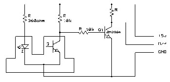
Figure1.Circuit Diagram of Interrupter Module
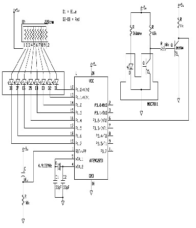
Figure1.Circuit Diagram of Hardware.
Mechanical assembly plays a vital role in proper functioning
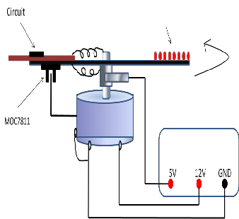
of this project. The display is scanned each time, by rotating the whole assembly in a circular path. The basic idea we developed is on our own, by implementing and modifying different ways to do this. Following diagram shows the most reliable way, that we finally selected. Here, one major challenge was how to bring +5V supply to the spinning circuit. We tried the same by adopting two-three different methods, but finally concluded on the method, as shown in the figure. As seen in the diagram, one supply connection (GND) is provided through the motor’s shaft. Other terminal (Vcc) is connected, by arranging a friction disc-brush arrangement. The brush keeps its contact with the Disc, so that current can be supplied. Most critical objective was to achieve pristine balance and overall good mechanical strength. For weight adjustment, we have provided one long screw, and weight can be attached or removed by adding / removing metallic bolts. If the assembly is balanced perfect, then it can achieve stability, and rotate at high RPMs too. This will improve the overall efficiency of this display.
IJSER © 2012 http://www.ijser.org
The research paper published by IJSER journal is about The Power Saving Low Cost Rotating 8 Led Information Display 3
ISSN 2229-5518

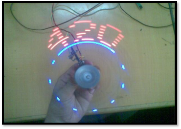
Figure3.Mechanical Assembly
A fixed voltage power supply producing constant +5V consists of step down transformer, a bridge rectifier, filter capacitors C1 and 3 terminal regulator IC LM7805. A step down transformer is selected in such a way that it produces 9V at the input of IC. This power supply is capable of supplying +5v and load current up to 500m A. The capacitor C2 connected between output terminal and ground cancels out any inductive effect due to long distribution leads. Input capacitor C1 is used to improve transient response of the regulator IC, i.e. response of regulator to sudden changes in load. It is also helpful in reducing the noise present in the output. Dropout voltage (Vin-Vout) needs to be at least 2V under all operating conditions for proper operation of regulator.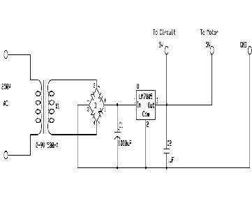
Figure2. Circuit Diagram of Power Supply.
IJSER © 2012 http://www.ijser.org
International journal of scientific & engineering research, volume 3, issue 5, march-2012
ISSN 2229-5518
![]() In each revolution as the beam is interrupted, the sensor generates a positive pulse.
In each revolution as the beam is interrupted, the sensor generates a positive pulse.
![]() Microcontroller will execute interrupt routine, when a pulse occurs.
Microcontroller will execute interrupt routine, when a pulse occurs.
![]() Interrupt routine measures the total time taken for one revolution,
Interrupt routine measures the total time taken for one revolution,
![]() Divides it by 120, and stores the result into another
Divides it by 120, and stores the result into another
timer,![]()
Configured in auto-reload mode.
Now, the timer overflows after tiny intervals of time.
Each time it overflows, next stored value is called from the lookup table, and displayed.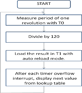
Figure1.Circuit Diagram of Interrupter Module.
This Interrupter module testing is required for detecting exact position of wheel on which whole circuit assembly is mounted. Supply voltage given to Pin. No. 1(Collector) and Pin.No.3 (Anode) of MOC7811=5.5VOutput voltage obtained at Pin.No.1 of MOC 7811 without interrupt=5.21v.Output voltage obtained at Pin.No.1 of MOC7811 with interrupt=0.08V
DC Motor used in this project is 12 V dc motor which is tested by using digital contact-less tachometer. Arrangement was made so that the sensing circuit gives high to low pulse for each completion of revolution. By measuring the time
difference between two successive pulses RPS can be calculated which further provide RPM value, as shown below: Power supply given to DC Motor = 9V
Time interval between two successive pulses as seen on CRO =
30.4ms
RPS = 1 / (30.4ms)
=32.89
RPS = 33
RPM= 33x60=1980
Power supply module was designed to provide 5V DC power supply necessary to drive both motor and circuit. AC input is given from 9V 750mA transformer. Results are as follows. Input voltage, Vs=9V AC.
Output voltage observed, Vo = 4.92V D
Power taken by the whole circuit is minimized by using this rotating 8 led information display. In the general led display which is available in the market , for displaying the single character we need 8x5 matrix led , it means for displaying a one character this display require 40 led’s. And one led consumed 75 miliAmphere current to glow. Therefore the total power consumed for displaying the single character is
8x5x75=3000 miliamphere current. If we want to display the 10
character we need 8x5x10= 400 led’s. Hence the power consumed by the 400 led’s also increased and 30,000 miliamphere current is consumed. But the same 10 character we are displaying by rotating 8 led’s in clockwise direction and switched at précised interval of time. This will result reduce in cost and also minimize the power consumptions for displaying the information.
IJSER © 2012 http://www.ijser.org
International journal of scientific & engineering research, volume 3, issue 5, march-2012
ISSN 2229-5518
*1+ Mitchell’s modular LED x-y (horizontally and vertically digitally scanned array system) was cited in the 29th International Science and Engineering Exposition "book of abstracts", page 97, published by the "Science Service", Washington D.C. May 1978.
[2] Technical reference detailing the LED display array, RF interface and scanning circuit was included as part of the 1978 29th ISEF exhibition in Anaheim, CA.
[3] Coltheart M. "The persistence of vision." Philos Trans R Soc Lond B Biol Sci.
1980 Jul 8; 290(1038):57–69.
*4+ ‚The 8051 microcontroller and Embedded Systems‛ by M.A.Mazidi. [5] Propeller Display Rennes’s H8 Design Contest 2003 Entry H3210 [6] An Analog & Digital propeller clock I made! By Luberth Dijkman.
IJSER © 2012 http://www.ijser.org