The research paper published by IJSER journal is about The Potential Use of Rotor Wing Unmanned Aerial Vehicle for Large Scale Stream Mapping 1
ISSN 2229-5518
The Potential Use of Rotor Wing Unmanned
Aerial Vehicle for Large Scale Stream Mapping
Wani Sofia Udin and Anuar Ahmad
Abstract - Unmanned Aerial Vehicle (UAV) systems offered many advantages in several mapping applications such as slope mapping, geohazard studies, etc.This study utilizes UAV system for large scale stream mapping by using digital camera attached to the UAV.The digital camera combined with the UAV form a data acquisition system. This study only concentrates on one type of rotor wing UAV. It is becaue rotor wing units are stable and able to capture images easily. Aerial photograph were acquired in the form of strips which followed the procedure of acquiring aerial photograph where the 60% forward lap and 30% sidelap. Secondary data of ground control points and check points established using Total Station technique was used. The digital camera was calibrated using close range photogrammetric software and the recovered camera calibration parameters were then used in the processing of digital images. All the aerial photographs were processed using digital photogrammetric software and the output in the form of orthophoto was produced. The research output is then evaluated for planimetry and vertical accuracy using root mean square error (RMSE). Based on the analysis, sub-meter accuracy is obtained. As conclusion, rotor wing UAV system has potential use for large scale stream mapping or other diversified applications especially for small area which has limited time and less man power.
Keywords- unmanned aerial vehicle, stream, digital camera, accuracy
1 INTRODUCTION
HOTOGRAMMETRY means a three dimensional coordinate measuring technique which utilizes photographs as the fundamental medium for measurement. Early development in the theory and science of photogrammetry occurred many years before the actual invention of a suitable means to apply the application. Over the years, photogrammetry has gone through several development phases and now entered into digital photogrammetry phase. Photogrammetry can be divided into aerial photogrammetry and terrestrial photogrammetry. Aerial photogrammetry involves the acquisition of aerial photograph using metric camera from aircraft, helicopter, hot air balloon, kite or parachurte. It is costly and time consuming due to appropriate planning in order to gain efficient information. Besides, it needs photogrammetry expertise to operate the camera during flying mode. However, aerial photogrammetry is expensive and improper technique especially for large
scale mapping [1].
The demands of aerial photogrammetry have increased
especially after the development of design, research and
production of UAV platform [4], [5]. The compatibility of
small format camera introduces new era for
photogrammetrist. Furthermore, the widely used of
Unmanned Aerial Vehicle (UAV) among civilian has
beneficial photogrammetry world.
————————————————
Wani Sofia Udin is currently pursuing doctor of philosophy program in geomatic engineering in Universiti Teknologi Malaysia, Johor, Malaysia, PH-0129495542. E-mail: wanisofia@umk.edu.my
Anuar Ahmad is lecturer and associate professor in department of geoinformatics in University Teknologi Malaysia, Johor, Malaysia, PH-
0197633125. E-mail: anuarahmad@utm.my
The UAV is exploited as the-state-of-the-art platform for small format digital aerial imagery acquisition which reduces the problem of cloud cover. With this advantage, UAV has been focused in the mapping research and various applications such as industrial, archaeology, architectural, geology, forestry, engineering and others.
These missions are very dangerous to the pilot who conducts the flight and need require longer durations from one to another destination. Hence, the development of remotely controlled aircraft without human on board can be implemented. Images taken from two UAVs that differed in size, payload capacity, flight duration, GPS guidance capability and cost has been used for determining the utility of UAVs for rangeland mapping [9].
According to “Bird et.al [3],” UAV system is also becomes very attractive among digital photogrammetric technique for modeling and monitoring of river beds at relatively high spatial resolution (0·01 to 1 m) through the extraction of digital elevation models (DEMs). A technique for capturing and analysis of close-range photogrammetric data acquired from a vertically mounted non-metric camera suspended 10 m above the channel bed has been implemented using a unipod. The camera was placed under the riparian forest canopy so that the channel bed can be imaged without obstruction. The system is convenient and permits relatively rapid image acquisition over rough terrain and in dense forest.
Based on the situations, this study is carried out to produce large scale mapping of stream mapping from digital aerial imagery of UAV platform. The orthophoto is then assessed with 3D coordinate established using Total Station technique. The study area is at Universiti Teknologi Malaysia (UTM) precinct by utilizing Sony Alpha NEX-5N digital camera mounted on Hexacopter rotor wing UAV.
IJSER © 2012 http://www.ijser.org
The research paper published by IJSER journal is about The Potential Use of Rotor Wing Unmanned Aerial Vehicle for Large Scale Stream Mapping 2
ISSN 2229-5518
2 UNMANNED AERIAL VEHICLE (UAV) AND DIGITAL CAMERA
Unmanned Aerial Vehicle (UAV) is an aircraft, flying in the air with no pilot onboard and with capability for remote controlling the aircraft as describe by [6]. UAV was developed by military during World War I and II for reconnaissance and surveillance purposes [7]. Today, the civilian is able to operate the UAV for photogrammetry application. Equipped with GPS, INS, autopilot system and others, the system is designed to collect data for mapping and image interpretation purposes working on areas. The advantages in developing the technology of UAV for low altitude photogrammetric mapping are to perform aerial photography at cloudy day, to get full image of object under study from aerial, and to supply a cheap and easy system for high frequency needs of aerial photogrammetric survey [8].
Micro UAV, also known as Hexacopter is considered as the type of low altitude UAV system. These platforms have
capability to capture images from certain altitude. The transmitter for hexacopter can received signal via radio control at five (5) kilometer radius. Hexacopter has been gathered with completed set device such as GPS on board, pressure board, speed board, gyro and mainboard. Figure
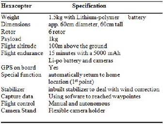
1 shows the hexacopter with the other device. As stated by “Tahar and Ahmad [10],” Hexacopter has six blades in which three blades rotate in clockwise direction and the other three blades rotate in counterclockwise direction. It offers images on demand and is an inexpensive alternative to satellite or flying on the airplane over a field. The specification of rotary wing used in this study is shown in Table 1.
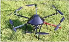
Fig. 1. Hexacopter
TABLE I
HEXACOPTER SPECIFICATION
Digital camera is categorized as non-metric camera where the camera is not specifically built for photogrammetric purposes. Digital camera is not characterized with fiducial mark, unstable calibration parameter, small format and many more [1]. Figure 2 shows the Sony Alpha NEX-5N digital camera with interactive 16.1 Megapixel. The digital camera has Tiltable
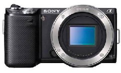
3.0" Touch liquid crystal display (LCD) screen. It is offers a high resolution, with a maximum 4912 x 3264 pixels. This camera was attached at the bottom of Hexacopter to capture aerial images during flight operation.
Fig. 2. Alpha NEX-5N digital camera
TABLE 2
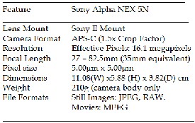
SONY ALPHA NEX-5N SPECIFICATION
The research paper published by IJSER journal is about The Potential Use of Rotor Wing Unmanned Aerial Vehicle for Large Scale Stream Mapping 3
ISSN 2229-5518
3 RESEARCH METHODOLOGY
The research methodology adopted in this study is shown in Figure 3. Each phase of the study is explained as the procedure of orthophoto production using digital aerial imagery.
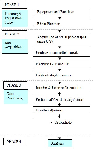
Fig. 3. Flow chart of research methodology
3.1 Planning and Preparation Stage
This stage investigates the purpose of the study. This phase involved the study area, software and instrument selection such as digital camera and types of UAV platform.The digital aerial imagery is processed using ERDAS Orthobase
8.6 for producing orthophoto of the streamTotal Station is used to establish the Ground Control Point (GCP) and Check Points (CP) for accuracy assessment. Due to focus under study, the photographic scale, flying height of UAV, coverage and others are determined. The area must be easily accessible. The area should include open area for easy takeoff and landing of the platform or UAV. Therefore, few aspects involved in preparation such as flight planning and properly install the instrument were considered. It involved the determination of 60% side lap and 30% end lap. A well-organized image requires an essential arrangement because it is vital for data processing
and analysis.
3.2 Data Acquisition
The study area is Universiti Teknologi Malaysia (UTM) main campus in Johor Bahru, Malaysia and it is shown by the red oval on the aerial photograph acquired using Wild RC30 aerial camera (Figure 4).This part of the stream is a
200m long regulated stretch, downstream of the main artificial lake. Water level and discharge are fairly low and constant in the natural bed of the river and the shallow waters are usually clear. Stream width varies between 3 and 10m. The digital aerial imagery is collected using digital camera mounted on Hexacopter. The aerial photograph must be acquired in a straight line and form a block of photograph. Flying height and speed were fixed, with an average flying height of 50 m. A timing interval was determined in order to obtain consistent flying axes with 60% overlapping. One strip of the image in JPEG (Joint Photographic Experts Group) is captured then transfers to the notebook for image processing. On-site calibration is also done for the aerial imagery. Figure 4 shows the study area and a strip of overlapping aerial photograph captured using the Sony Alpha NEX-5N digital camera of 16.1 megapixel resolutions.
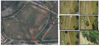
Fig. 4. Study Area (left) and example for a strip of aerial photograph (right)
3.3 Establishment of GCP and CP
The GCP and CP were established after the aerial photography mission and formation of uncontrolled mosaic is carried out. As for one strip of small format photograph, about 17 white crosses were painted as ground control points which enclosed the overlapped area as shown in Figure 5. Photogrammetric control targets were fixed alongside both plain as well as in two, almost straight, and coordinated by Total Station. Easy identification and clear image of the control points on the photograph increases the accuracy and efficiency of the photogrammetric process. The control points were painted on a hard surface to reduce the possibility of pre-marked points being moved or lost prior to the aerial mission. Targets were in symmetrical shape, adequate size, and appropriate photographic contrast and resolution. These target points provided sufficient control for photogrammetric processing, as well as providing check point data to access accuracy.
The research paper published by IJSER journal is about The Potential Use of Rotor Wing Unmanned Aerial Vehicle for Large Scale Stream Mapping 4
ISSN 2229-5518
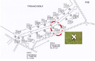
Fig. 5. The location of GCP and CP
3.4 Camera Calibration
Camera calibration is carried out before image processing is done. It is done by capturing convergence image of a test field which comprises of several targets and scale bar. The method used is self-calibration bundle adjustment method. A camera calibration plate with dimension of 0.6meter x
0.6meter and consist of 36 reflective points were used as a camera calibration platform. The digital camera is used to capture image of the calibration plate at four positions, including landscape and portrait position. The angle and distance between calibration plate and camera at four positions should be approximately the same. The images from four different positions were processed using Australis software and the results of calibration are shown in Table 3.The camera calibration parameters consist of the focal length (c), principal point offset (xp, yp), radial (k1, k2, k3) and tangential (p1, p2, p3) lens distortion, “affinity” (b1) and different in scale factor (b2).
TABLE 3
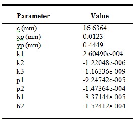
THE CAMERA CALIBRATION PARAMETERS OF SONY ALPHA NEX-5N DIGITAL CAMERA
3.5 Data Processing
Digital image processing is carried out in this phase for deriving orthophoto from UAV imagery. The ERDAS Orthobase is exploited to process the digital image of small format camera. Raw images went through certain photogrammetric processed such as interior orientation, exterior orientation, aerial triangulation and bundle adjustment. The GCPs is used to perform the aerial triangulation in order to produce stereoscopic model. In the software, the 3D stereoscopic model was setup within short period of time [2]. Ground control points were also used to geo-reference images to the local coordinate system. The step is continued by generating orthophoto of the digital aerial imagery.
3.6 Analysis
Last stage of the study comprises of analysis in qualitative and quantitative technique. The qualitative is done by analyzing the quality of orthophoto and DTM generation. Meanwhile, the quantitative analysis is performed by using Root Mean Square Error (RMSE). The arbitrary coordinates system (X, Y, and Z) of control and check points derived using Total station were compared with estimates established by photogrammetry. The RMSE is carried out by using equation shown in Equation 1.
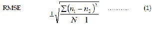
where,
n1 = differences value between two parametres
n2 = mean differentiation
N = total no. of points
4 RESULTS
Based on the study, two sets of output are obtained. The first result is camera calibration parameter derived from camera calibration process. The second result is orthophoto.
4.1 Aerial Triangulation
Figure 6 depicts the triangulation summary and the image Root Mean Square Error (RMSE) of the unit weight. The triangulation summary showed that the Unit Weigt RMSE of the Alpha NEX-5N digital camera is ±0.1020. During image processing, the accuracy was maintained by checking the value of RMSE. The value of RMSE must be less than 1.0 in order to obtain good results. RMS error is reported in pixels. After performing AT, the footprint of the AT can be displayed. Figure 7 shows the graphic display of small format aerial photograph in Erdas Imagine software. The foot prints of the aerial photographs showing the location and names of all points (i.e control points, check points and tie points) that participated in the adjustment.
The research paper published by IJSER journal is about The Potential Use of Rotor Wing Unmanned Aerial Vehicle for Large Scale Stream Mapping 5
ISSN 2229-5518
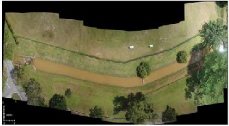
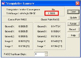
Fig. 6. Triangulation summary
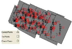
Fig. 7. Footprint of AT for small format aerial photograph in Erdas Imagine
4.2 Orthophoto
Subsequently, a series of digital aerial imagery of the small format non-metric camera was used to produce orthophoto. The orthophoto was created after the formation of aerial triangulation of digital imagery with
60% endlap and 30% sidelap overlapping by using established GCPs. A stereomodel in three dimensional (3D) was successfully produced and orthophoto can be visualized. Based on the Figure 7, the actual flight path is clearly seen that crabbing occurred during the process of photography. Even though the UAV is expected to follow a straight line, it suffers crabbing due to the wind speed. Figure 8 depicts the orthophoto of the stream digital aerial imagery.
Fig. 8. Orthophoto of stream digital aerial imagery
5 ANALYSIS
The orthophoto generated was analyzed by comparing with Total Station coordinate. The accuracy of orthophoto planimetry and vertical is shown in Table 4. In planimetry accuracy, a sub-meter ±0.164m and ±0.223 m were obtained for X and Y coordinates respectively. Meanwhile the RMSE for Z coordinates is ±0.639. For average RMSE, ±0.342m was obtained by averaging the planimetry and vertical RMSE of small format digital imagery orthophoto.
TABLE 4
RMSE OF DIGITAL AERIAL IMAGERY ORTHOPHOTO AND TOTAL STATION
Check Points | Erdas Imagine 8.6 | Total station | Diff. in Coordinates |
Check Points | X (m) | Y (m) | Z (m) | X (m) | Y (m) | Z (m) | ∆X (m) | ∆Y (m) | ∆Z (m) |
CP03 | 627466.554 | 172062.984 | 15.485 | 627466.488 | 172062.848 | 14.862 | 0.066 | 0.136 | 0.623 |
CP05 | 627480.570 | 172103.758 | 14.170 | 627480.460 | 172103.733 | 14.759 | 0.110 | 0.025 | -0.589 |
CP13 | 627453.803 | 172083.455 | 13.864 | 627453.996 | 172083.319 | 14.700 | -0.193 | 0.136 | -0.836 |
CP15 | 627436.592 | 172036.295 | 13.396 | 627436.409 | 172036.630 | 13.566 | 0.183 | -0.335 | -0.170 |
| RMSE | 0.164 | 0.223 | 0.639 |
| Average | 0.342 |
|
6 CONCLUSION
Based on this study, the digital aerial imagery of rotor wing hexacopter can be used for large scale stream mapping. The sub-meter accuracy produced by the data is relevant for various applications with low cost expenditure and less expert manpower. Besides, the flexibility and high efficiency of the UAV flight would be a solution for real-time mapping. It is because UAV can take-off and landing at limited open area with autopilot controlling. The map or the orthophoto produced from this system can be used in various fields such as Geographical Information System (GIS), geomatic, engineering, construction industry, planning etc. This study is more extensive if compared to the previous work done by [11]. The previous work used the low cost digital camera mounted on fixed wing Cropcam UAV. The study is performs to assess the accuracy of DTM derived from UAV platform. The research output is then evaluated for planimetry and vertical accuracy using RMSE.
The research paper published by IJSER journal is about The Potential Use of Rotor Wing Unmanned Aerial Vehicle for Large Scale Stream Mapping 6
ISSN 2229-5518
ACKNOWLEDGMENT
The authors would like to acknowledge the support of Faculty of Geoinformation & Real Estate in conducting this study. The authors would like to express their great thanks to Universiti Malaysia Kelantan (UMK) for surpporting this work. Further, authors would like to thanks the Research Management Center (RMC) of Universiti Teknologi Malaysia and Ministry of Higher Education Malaysia for guidance and supporting this study.
REFERENCES
[1] A.Ahmad, “Digital Mapping Using Low Altitude UAV,”Pertanika
Journal of Science and Technology. Vol. 19 (S): pg 51 – 58 Oct 2011.
[2] A.Ahmad, K.A. Hashim and A.M. Samad, “Aerial Mapping using High Resolution Digital Camera and Unmanned Aerial Vehicle for Geographical Information System;”2010 6th International Colloquium on Signal Processing & Its Applications (CSPA). Pg 201 – 206, 2010.
[3] S.Bird, D.Hogan and J.Schwab, “Photogrammetric Monitoring Of Small Streams Under A Riparian Forest Canopy,”Earth Surface Processes and Landforms. Volume 35, Issue 8, pages 952-970, 30 June 2010.
[4] R.P.Breckenridge and M.E.Dakins, “Evaluation of Bare Ground on
Rangelands using Unmanned Aerial Vehicles: A case study,” GIScience. Rem. Sens., 48(1): 74-85,2011.
[5] H.Y.Chao, Y.C.Cao and Y.Q. Chen, “Autopilots for Small Unmanned
Aerial Vehicles: A Survey,” Int. J. Contr. Automation. Syst., 8(1): 36-
44,2010.
[6] U.Coppa,A. Guarnieri, F. Pirotti and A.Vettore, “Accuracy Enhancement of Unmanned Helicopter Poisitioning with Low Cost System,”ISPRS (International Society of Photogrammetry and Remote Sensing . Vol. XXI Congress, Beijing, China, 2008.
[7] H.Eisenbeiss, “A Mini Unmanned Aerial Vehicle (UAV): System Overview And Image Acquisition,”International Workshop on Processing and Visualization Using High-Resolution Imagery. Nov
2004. Pitsanulok, Thailand, 2004.
[8] L.Z.Jian, “UAV for Mapping – Low Altitude Photogrammetric Survey,” The International Archives of The Photogrammetry, Remote Sensing and Spatial Information Sciences. Part B1. XXXVII, 1183-1186, 2008.
[9] A.Laliberte, A.Rango and J.E. Herrick, “Unmanned Aerial Vehicles for Rangeland Mapping and Monitoring: A Comparison of Two Systems,” American Society for Photogrammetry and Remote Sensing Proceedings, May 7-11, 2007, Tampa, Florida. 2007.
[10] K.N. Tahar and A.Ahmad, “A Simulation Study On The Capabilities Of Rotor Wing Unmanned Aerial Vehicle In Aerial Terrain Mapping,”International Journal Of Physical Sciences Vol. 7(8), Pp.
1300 - 1306, 2012
[11] W.S. Udin, A.F.Hassan, A.Ahmad and K.N. Tahar, “Digital Terrain Model Extraction Using Digital Aerial Imagery Of Unmanned Aerial Vehicle,”2012 IEEE 8th International Colloquium On Signal Processing And Its Applications (CSPA), 23-25 March 2012, Malacca, Malaysia.