International Journal of Scientific & Engineering Research, Volume 3, Issue 6, June-2012 1
ISSN 2229-5518
The Non-divergence Newton-Based Load Flow
Method in Ill Conditioned system
A.Shahriari, H. Mokhlis, A. H. A. Bakar, M. Karimi, M. M. Aman
Abstract— This paper implements the Optimal Multiplier Load Flow Method (OMLFM) in polar coordinate form to calculate low voltage solution and maximum loading point of system in ill conditioned system. OMLFM modifies the direction of state variables (buses voltage and phase) by using optimal multiplier in order to the convergence of load flow equations in ill conditioned system. The privilege of OMLFM emerges in keeping dimension of load flow jacobian matrix constant. W hile another method such as continuation and homotopy methods change the framework of jacobian matrix based on predictor and corrector steps in term of increasing load demand. Actually, the calculation process of SSSM is based on standard Newton Raphson load flow method. The validation of OMLFM for maximum loading point as ill-conditioned system is shown by testing IEEE 57 bus test system. Furthermore, the 13 bus radial transmission system is tested to with verify OMLFM for ill conditioned system includes high R/X ratio lines and the weak interconnection.
Index Terms— Optimal Multiplier Load Flow Method, low voltage solution, optimal multiplier, ill conditioned system
.
—————————— ——————————
conomic, Environmental, and technical problems such as the difficulty in construction of new transmission lines, new generation plants, and the raising load demand have let power system to operate near to its limit capacity[1, 2]. This is emerged in approaching to Maximum Loading Point (MLP), transmission lines with high R/X ratio and bus connections have a very high resistance and very low impedance that caus- ing the power system becomes ill-conditioned system [3]. Therefore, chance of the voltage collapse phenomenon is in- creased due to power system operation in the instability zone [4]. Although, voltage collapse is a dynamic problem, it can be considered as a static issue if the power systems parameters change slowly [5]. The change in these parameters corresponds to a small load increase in power system. Hence, a set of static nonlinear algebraic equations of the power flow equations is considered for the voltage stability study [6]. In this context, a several approaches based on power flow equations have been introduced to determine load flow solutions in ill conditioned system. This case forces the power flow equations to have Low Voltage Solution (LVS) or solution Type-1 as unstable equili- brium operation point. Under this condition, the original pow- er flow solutions as interesting power flow solution is called
High Voltage Solution (HVS) [7].
In this regard, two main approaches are have been presented in
order to find power system low voltage solutions, the Optimal
Multiplier Load Flow Method (OMLFM) and path follow ing
————————————————
![]() A. Shahriari is with Department of Electrical Engineering, Faculty of E n- gineering, University of Malaya, Kuala Lumpur 50603, Malaysia. PH-
A. Shahriari is with Department of Electrical Engineering, Faculty of E n- gineering, University of Malaya, Kuala Lumpur 50603, Malaysia. PH-
+60129723448. E-mail: shahriariamid@siswa.um.edu.my
![]() H. Mokhlis is with Department of Electrical Engineering, Faculty of Engi-
H. Mokhlis is with Department of Electrical Engineering, Faculty of Engi-
neering, University of Malaya, Kuala Lumpur 50603, Malaysia. E-mail:
hazli@um.edu.my![]()
![]() Ab. Halim Abu Bakar is with UM Power Energy Dedicated Advanced Centre (UMPEDAC), Level 4, Wisma R&D, University of Malaya, Ma- laysia. E-mail: a.halim@um.edu.my
Ab. Halim Abu Bakar is with UM Power Energy Dedicated Advanced Centre (UMPEDAC), Level 4, Wisma R&D, University of Malaya, Ma- laysia. E-mail: a.halim@um.edu.my
methods (PFM) [7, 8]. PFM utilizes trajectory of load demand enhancement in PV curves to detect MLP and beyond it [9]. This method is powerful and robust for detecting LVS [10]. However, PFM needs a large number of iteration and any prior information of the direction of load increasing to converge [7]. Also, PFM could not handle ill–conditioned and unsolvable condition in appropriate manner [11]. The PFM is classified as the Continuation methods (CM) and the Homotopy methods (HM) [9, 11, 12]. In contrary of CM, OMLFM does not need to several iterations and any previous information of direction of load demand increasing to calculate LVSs [13]. Because, OMLFM is based on Newton Raphson Load Flow Method (NRLFM) using optimal multiplier [13, 14]. The optimal multip- lier as accelerator damper converges the load flow equations in ill conditioned systems [15].
This paper utilizes the OMLFM in polar coordinate to find LVS at Maximum loading point, high R/X ratio and the weak interconnection as ill-conditionding. The polar coordinate com- pares with rectangular coordinate is system is more appropriate for power flow solution for ill-conditioned. Furthermore, polar coordinate form prevents switching all of PV type buses to PQ that happened in rectangular form [17, 18, 19]. The contribution of this paper is apparent in introducing the proposed algorithm based on OMLFM in order to obtain LVS’s and MLP simulta- neously. To evaluate the proposed method, case studies based on IEEE 57 bus test system and and 13 bus radial transmission system, in well and ill-conditioned systems are tested [20].
The power flow equations as a set of nonlinear equations can be written as:
M. Karimi is with Department of Electrical Engineering, Faculty of Engi-
neering, University of Malaya, Kuala Lumpur 50603, Malaysia. E -mail:
![]()
mazaher@ siswa.um.edu.my
Where![]()
F ( X , H ) 0
(1)
M. M. Aman is with Department of Electrical Engineering, Faculty of
Engineering, University of Malaya, Kuala Lumpur 50603, Malaysia.
X - Vector of independent (state) variables.
H - Vector of dependent variables
IJSER © 2012
International Journal of Scientific & Engineering Research, Volume 3, Issue 6, June-2012 2
ISSN 2229-5518
F- Load flow function
The E.q (1) involves only two variables i.e. bus voltage ampli- tude ( X a ) and its angle ( X b ) at buses as independent variables in polar coordinate form. Since, Taylor series, expansion of E.q (1) based on these state variables is formulated as follow:
![]()
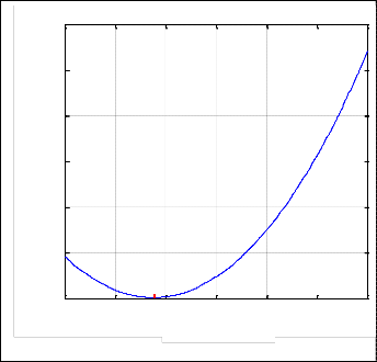
Iba et al. improved that the optimum points of multiplier cost function as quartic function in E.q (6) has a two minimum points and one maximum point [14]. The assumption illustra- tion of E.q (6) is depicted in Fig.1. In well conditioned system, the classical newton-based method can only detect on these minimum points as interested solution point called the high voltage solution (HVS). For this case is equal to one. In ill
i i i i i i
![]()
i i i
conditioned system, by increasing the load demand of system,
F ( X a
X a , X b
![]()
1 i i
X b )
T
F ( X a , X b )
2 i
X , X F X a , X b
i i
![]()
two minimum points of E.q (6) are forced to get closer to each other and meet at MLP located at maximum point of Fig.1. For
2 X a ,
X b X , X F X a , X b
0 (2)
this condition the closet value of to one is selected as the optimal multiplier to find LVS. Furthermore, it can be ob-![]()

The standard Newton-based methods can solve E.q (2) by neg- lecting the second term E.q (2). But in ill conditioned system first initial estimation of newton-based methods state variables such as Newton Raphson Load Flow Method (NRLFM) is far away from real solution. For this purpose, the Optimal Mul- tiplier Load Flow Method (OMLFM) modifies the direction of state variables in state space from first initial estimation in order to find best stable solution or low voltages solutions [7,
13]. Therefore, the modification of next step of state variables is
served that E.q (6) is based on NRLFM.
C
C
MAX
X i 1 X i X i
(3)
MIN
where is multiplier damper that is used to modify the mis- match vector of state variables. Since, E.q (3) can be rewritten by using
MIN
Fig.1.Illustration of assumption multiplier cost function re-
i i i i i i i
i i i
spect .
F ( X a
X a , X b
X b )
F ( X a , X b )
X , X F X a , X b
1 2 i ,
i T 2
i i , i 0
2 i X a
X b X , X F X a X b
(4)![]()
![]()
However, optimal multiplier is computed by minimizing![]() is called optimal multiplier due to optimization method based on nonlinear programming technique is utilized to cal- culate it. Under this condition the multiplier cost function in
is called optimal multiplier due to optimization method based on nonlinear programming technique is utilized to cal- culate it. Under this condition the multiplier cost function in
E.q (6) respect with as
(7)
E.q (5) is defined as objective function in order to obtain then the correction value of state variable as follows![]()
dL DT E
d
(DT D
2GT D) 3ET G 2
2GGT 3 0
1 i i i i i i i i i i
![]()
Where E=-D in order to simplify (7) [13].
C 2 F ( X a
X a , X b
X b )
F ( X a , X b )
X a , X b F X a , X b
The Cardan method is used to find possible real roots of this cubic equation. E.q (7) has three real roots in well-conditioned![]()
1 2 i ,
i T 2
i i , i
0 (5)
system. The numbers of real solutions of E.q (7) are decreased
i X a
X b X , X F X a X b
2 a b
We can get by manipulating (5) to
at MLP. E.q (7) does not have any real solution in infeasible
operation zone beyond MLP.
The proposed algorithm based on OMLFM to calculate LVS in
terms of load demand increasing is as follows![]()
1 T T T T 2 T 3 T 4
[D D
2
2D E
(E E
2G D) 2E G GG
] (6)
Increase predefined load demands based defined step then![]()
![]()
![]()
run NRLFM![]()
![]()
1 2 T 2
C D E
2
G D E G
1-If NRLFM converges go to 1 otherwise go to 3
2-Calculate the closet optimal multiplier to one of equation (6)
by using cardan method due to calculate low voltage solu-
where
D F( X i a
X i , X i a b
![]()
X i ) F( X i , X i )
b a b
tions.
3-Increase load demands based defined step
B X , X F
X a , b
4- If that E.q (7) has a real solution (as index to approaching to
a b
1 2 X i , i T
2 i b
i
![]()
X a , X b F
![]()
X i , i ![]()
MLP) stop process and calculate the LVS based on this optimal multiplier otherwise go to (3).
IJSER © 2012
International Journal of Scientific & Engineering Research, Volume 3, Issue 6, June-2012 | 3 |
ISSN 2229-5518 |
IEEE 57- bus test system is tested to show convergence cha- racteristics of OMLFM at MLP as ill-conditioned system. The linear active and reactive load demand models are utilized to detect the maximum loading point of this system as follows [15]:![]()
(8)![]()
23 1.00366 -0.232048 -0.0409509 -608.772
24 0.99534 -0.237434 0.00594188 -389.213
25 0.97804 -0.324235 0.136447 -1171.4
26 0.95515 -0.232163 0.0127438 -64.5743
27 0.97935 -0.205333 0.451047 -197.135
28 0.99513 -0.186871 0.658432 -194.071
29 1.00906 -0.17423 0.80046 -193.041
30 0.95785 -0.334146 0.33876 -1163.4
31 0.93046 -0.346596 0.582395 -810.355
P P0
![]()
Q Q0
P
Q (9)
32 0.94372 -0.332325 -0.419363 -694.734
33 0.94143 -0.333027 -0.470902 -610.467
34 0.95513 -0.252822 0.410462 -1870.77
Where P0 and Q0 are the intial and actual vector of active
and reactive powers. Alfa (α) involves the step size and the
direction the load demand changing. The calculated MLP
based on proposed algorithm with α=0.001 this system is 1.92.
The newton-based methods cannot converge in ill conditioned
system due to the fact the region of LVS if far away from their
initial guess. The Table 1 shows the divergence characteristics
of NRLFM in calculating LVS’s at MLP of IEEE 57 bus. Also,
the drastic difference between load flow solutions in ill and well -conditioned for both systems confirms that the result of NRLFM is not at vicinity of its initial guess in ill conditioned system.
35 0.96213 -0.248674 0.145749 -1885.93
36 0.97178 -0.243984 0.00944599 -1959.29
37 0.98061 -0.240741 -4.66e-005 -1035.23
38 1.00797 -0.228583 -0.0472536 -800.697
39 0.97861 -0.241493 -0.01187 -990.499
TABLE 1
The Performance of Standard Newton Raphson Method for
IEEE 57 Bus System In Well and Ill Conditioned System
On the other hand, the value of phase angle at MLP in Ta- ble 1 implies the enhancement of buses voltage angle during demand increasing declines the voltage stability margin. Due to voltage stability can be verified as a static issue if the power systems parameters change slowly.
The smallest bus voltage value from the SNRLF is at bus
33 (-0.470902 p.u.). This unreasonable bus voltage value
does not have any physical interpretation from power sys-
tem point of view. The performance of OMLFM to find LVS
at MLP is shown in Table 2. On account of value of voltage in
TABLE II can be assessed that OMLFM computes the possible
lowest LVS. Base on this fact, bus 31 in IEEE 57 bus system is the weakest buses in ill conditioned. Other meaning, bus 31 in IEEE 57bus system is selected as the most sensitive bus for contingency analysis for voltage collapse in ill conditioned.
Multiplier cost functions in E.q (6) for 57 IEEE bus system is depicted in Fig.2. IEEE 57 bus system has the one optimal mul- tiplier at MLP. The value of optimal multiplier is 7.50337e-005 shown by X in Fig.2. Indeed, the values of multiplier at mini- mum points of IEEE 57 bus system multiplier cost function is
IJSER © 2012
International Journal of Scientific & Engineering Research, Volume 3, Issue 6, June-2012 4
ISSN 2229-5518
![]()
the optimal multiplier. It can be seen the existence of a single optimal multiplies at MLP. The important point in this context is that the value of optimal multiplier force to zero at MLP. The used scale for multiplier cost function of 57 IEEE bus sys- tem is 0.0001.
-5
x 10
3
2. 5
2
. 5
1
. 5
X
0
-1 0 1 2 3 4 5
λ x 10-4
Fig.2. Illustration of multiplier cost function for IEEE 57 bus system.
TABLE2
The Performance of Otimal Multiplier Load Flow Method
for IEEE 57 Bus System at Maximum Loading as Point Ill![]()
![]()
Conditioned System![]()
![]()
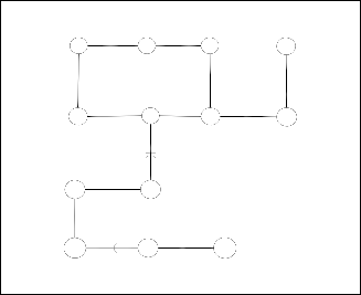
The 13 bus radial transmission system is considered to verify OMLFM for ill conditioned system includes high R/X ratio lines and the weak interconnection.The 13 bus ill- conditioned systemsis shown in Fig. 3. The lines and buses data is available in [3]. The heavy buses loading, the position of the slack- generator, certain radial system type and two series capacitors result this system to be ill.![]()
IJSER © 2012
International Journal of Scientific & Engineering Research, Volume 3, Issue 6, June-2012 5
ISSN 2229-5518
Slack Node
6 2 1 5
7 8 3 4
Line
Capacitor
12 13
For this case, ratio of maximum eigenvalue to minimum ei- genvalue as condition the number of the jacobain is very high and is 1000. This is reason of the divergence or osculation of NRLFM in ill conditioned system. OMLFM is used to deter- mine the voltage margin at neighborhood of MLP. thus, OMLFM defines active and reactive power limitations to con- trol buses angles and voltage amplitude. Therefore, bus 13 is used to illustrate the effect of the OMLFM on the improve- ment of voltage instability of Bus 13 due to its vicinity besides heavy load demanding in Bus 12 and series capacitor between buses in line 13-8. The effect of OMLFM is illustrated in Fig. 6.
11 10 9
Fig3. The line diagram of 13 bus ill-conditioned system
Under this condition, the load flow equation jacobian becomes singular. Therefore, the eigenvalues of the studied ill- conditioned system’s jocobian matrix are very sensitive to small changing in states variables. Fig.4 depicts the sparisity of this singular jacobian matrix. 4. Furthermore, solid geometry of sparse jocobian matrix shown in Fig.5.
solvable critical point
Reactive Power (p.u)
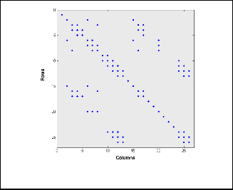
Fig.6. The performance of OMLFM in defining critical point of
Fig.6 shows the enhancement of voltage of bus 13 in term of The increasing of the reactive power demand. It implies the OMLFM attempt to keep voltage amplitude at Bus 13 in ac- ceptable level. It can be seen that the voltage drops signifi- cantly at 1.6 p.u of reactive power of bus 13. The MLP of this bus is occurred at 1.8 p.u of its injected reactive power.
The value of voltage of bus 13 at MLP is 0.892 p.u founded by OMLFM. Accordingly, the capability of OMLFM is also ap- parent in the calculation MLP for ill radial transmission sys- tem.
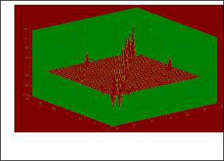
Fig.4. Sparse jacobian matrix for 13bus ill- conditioned system
Row Column
Fig.5. Solid geometry of sparse jocobian matrix of 13 bus ill- conditioned system
This paper presents Optimal Multiplier Load Flow Method (OMLFM) is a robust, reliable and simple method to calculate Low Voltage solution (LVS) in ill conditioned systems. In ad- dition, it has been shown that the proposed algorithms based on OMLFM can obtain LVS’s and MLP simultaneously. under this condition , the closet optimal multiplier to one has been selected as the desirable optimal multiplier to find LVS’s at MLP. The ability of OMLFM has been validated by IEEE 57 bus test system and 13 bus radial transmission system.
[1] B. Stott, ―Review of load-flow calculation methods‖, Proc. IEEE, vol. 62 n.
1, , pp. 916–929.July 1974.
[2] Wang. Y, da Silva. L.C.P and Wilsun Xu, Investigation of the relationship between ill-conditioned power flow and voltage collapse, IEEE Power En- gineering Review, pp. 43-45 vol.20 n.4, July 2000.
IJSER © 2012
International Journal of Scientific & Engineering Research, Volume 3, Issue 6, June-2012 6
ISSN 2229-5518
[3] S. C. Tripathy, G. D. Prasad, O. P. Malik, and G. S. Hope, ―Load-flow solu- tions for ill- conditioned power systems by a Newton-like method,‖ IEEE Trans. Power App. Syst., vol.101 n.1, October 1982. pp. 3648–3657
[4] Y. Tamura, H. Mori and S. Iwamoto, ―Relationship Between Voltage
Instability and Multiple Load Flow Solutions in Electric Power Systems‖ ,
IEEE Trans. Power App .Syst., vol. 102 n. 5 pp.1115 – 1125, May 1983.
[5] R. J. Avalos, C. A. Cañizares, F. Milano, and A. Conejo, Equivalency of
Continuation and Optimization Methods to Determine Saddle-node and Limit induced Bifurcations in Power Systems, IEEE Trans. Power Cir. Syst, vol. 56 n.1, January. 2009, pp. 210-223.
[6] Ning Xie, Ettore Bompard, Roberto, Napoli Franco Torelli ―Widely conver- gent method for finding solutions of simultaneous nonlinear equations‖. Electric Power Systems Research journal Volume 83, Issue 1, Pages 1-266
February 2012.
[7] S.K. Goswami, P. Acharjee ―Multiple low voltage power flow solutions using hybrid PSO and optimal multiplier method‖ Expert. Syst. Appl., 37
(2010), pp. 2473–2476
[8] F. Milano, Continuous Newton’s Method for Power Flow analysis, IEEE Trans. Power Syst, Vol. 24 n.1, pp. 50-57, February 2009.
[9] J. F. Gutiérrez; M. F. Bedriñana ;C.A.Castro. ―Critical comparison of robust load flow methods for ill-conditioned systems‖ IEEE Conference Trond- heim, 2011
[10] Shao-Hua Li and Hsiao-Dong Chiang, “Continuation Power Flow With
Nonlinear Power Injection Variations: A Piecewise Linear Approximation‖,
IEEE Trans. Power Syst, vol. 23 n.4 pp. 1637 – 1643., November 2008.
[11] Y. Zhang, H. Chiang, ―Fast newton-FGMRES solver for largescalepower
flow study,‖ IEEE Transactions on Power Systems, vol. 25,no. 4, pp. 769 –
776, May 2010.
[12] G.-Y. Cao and D. Hill, ―Power system voltage small -disturbance
stabilitystudies based on the power flow equation,‖ Generation,
TransmissionDistribution, IET, vol. 4, no. 7, pp. 873–882, july 2010.
[13] S. Iwamoto and Y. Tamura, A load flow calculation method for ill condi- tioned power systems, IEEE Trans. Power App. Syst., vol. 100 n .3, , pp.
1736–1743,April1981.
[14] K. Iba, H. Suzuki, M. Egawa, and T.Watanabe, A method for finding a pair of multiple load flow solutions in bulk power systems, IEEE Trans. Power
Syst., vol. 5 n.2, pp. 582–591, May 1990.
[15] T. J. Overbye and R. P. Klump, Effective calculation of power system low - voltage solutions, IEEE Trans. Power Syst., vol. 11 n.1 pp.75-82 ., February
1996.
[16] M. D. Schaffer and D. J. Tylavsky, A nondiverging polar form Newton - based power flow, IEEE Trans. Ind. App., vol. 24 n.1, pp.870–
877.September/October 1988.
[17] L. M. C. Braz, C. A. Castro, and C. A. F. Murari , A critical evaluation of step size optimization based load flow methods, IEEE Trans. Power Syst.,
vol. 15 n.1, , pp. 202–207, February 2000
[18] J. E. Tate and T. J. Overbye, A comparison of the optimal multiplier in polar and rectangular coordinates, IEEE Trans. Power Syst., vol. 20 n 4. , pp.
1667–1674, November 2005.
[19] Huang,W.-T.;Yao,K.-C.; ―New network sensitivity-based approach for real time complex power flow calculation‖ IET Generation, Transmission & Distribution 2011 Vol. 6, Iss. 2, pp. 109– 12. 2012
[20] Available: www.ee.washington.edu/research/pstca.
IJSER © 2012