International Journal of Scientific & Engineering Research, Volume 3, Issue 3, March-2012 1
ISSN 2229-5518
The influence of steel die parameter and micro- structural investigation on AA6063 aluminum alloy Gbenebor, O.P. , Adeosun, S.O. , Fayomi,O.S. , Joseph,O.O.
Abstract—The study investigated the influence of steel die parameter and the microstructural evaluation of AA 6063 aluminum alloy extruded at room
temperature using different die entry angles. Mild and tool steel dies of entry angles of 15o, 30o, 45o, 60o, 75o and 90o were used to extrude the work sample. Microstructural analysis, coupled with ram velocity, elongation, hardness, and maximum extrusion pressure of the extruded samples, were de- termined. It was observed that theaximum extrusion pressure required for extrusion and hardness of extruded samples increased with increasing die entry angle .Experimental results show that aluminum alloy deforms better when the die material is made of mild steel with die entry angles of 45 o, 75o and 90o as compared to tool steel.
Index Terms— AA6063 aluminum alloy, die entry angle, extrusion, extrusion pressure, extrusion ratio, microstructure, ram velocity
1 INTRODUCTION
—————————— ——————————
A 6063 is a heat treatable and wieldable aluminum alloy with magnesium and silicon as the alloying elements. Owing to its good mechanical properties, this alloy is mostly used in extruded shapes for architecture - win-
dow frames, door frames and roofs [1-8].The process of metal
extrusion entails the forcing of a stock of material in the form of a billet, which is placed in a chamber, through a die opening (which could be of any shape) by the use of a ram [2-5].
A variety of shaped aluminum components are extruded at room temperatures to obtain good surface finishes, better di- mensional consistency and improved strengths [3-6]. Investi- gations on effects of die profile associated with some other extrusion parameters like extrusion/ram pressure, ram speed, metal flow, nature of friction and product defects have been areas of interests for extrusion researches [7-8].
Tool steels are majorly used as die materials because of the high strength and good wear resistance they possess, however, these alloys are expensive (cost of manufacturing or procure- ment) compared to mild steel, which is readily available and cheap to form [7-10]. It is therefore necessary to investigate the products of aluminum extrudates when a mild steel is used as a die material and see if it could reasonably substitute tool steel die (to some extent ) in extrusion applications.
2 MATERIALS AND METHODS
2.1 Material preparation
AA 6063 aluminum alloy used for this study was obtained
from Nigeria Aluminum Extrusion Company (NIGALEX), Oshodi Lagos, Nigeria. The chemical analysis of this alloy is shown in Table 1.
Table1 Aluminum alloy AA 6063 spectrometer analysis

The alloy was heated above its melting temperature (660oC)
and was cast in a sand mould with cylindrical sample of
30mm x 300mm. The metals were allowed to solidify and
ejected by breaking the mould. The cast samples were cleaned and machined to the shape and size as shown in Figure1 for the extrusion process.
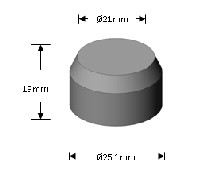
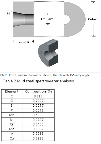
Fig1. Schematic diagram of the specimen to be extruded
2.2 Die and form tool materials
IJSER © 2012
http://www.ijser.org
International Journal of Scientific & Engineering Research, Volume 3, Issue 3, March-2012 2
ISSN 2229-5518
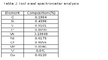
Mild and tool steels of chemical compositions shown in tables
2 and 3, were used as the die material of which each steel .was
machined to form a circular end section and entry angles of 15,
30,45,60,75 and 90 degrees were made for each die material,
making twelve dies in all. The mild steel dies were annealed
by first heating them to a temperature of 850oC and held for three hours at this temperature. The tool steel dies were nor- malized by heating them to a temperature of 750oC where they were held for three hours before they were brought out to cool in air. The form tool and the ram, which were made of mild steel were heated to a temperature of 850oC and quenched in water after holding for three hours in the furnace. This was done to increase the strength and hardness of the set up to
prevent wear and deformation during extrusion. 2.3 Extrusion
Extrusion was done at ambient temperature with the AVERY DENISON machine which was adapted to supply a compres- sive load on the ram. The die to be used was fitted into the form tool and the sample to be extruded was inserted through the upper cylindrical part of the form tool. The load (in KN) applied on the ram was read on this machine as a strain gauge was attached to the ram of the AVERY DENISON machine to measure the strain rate. Here, the time (in seconds), taken for the indicator on the strain gauge to complete a revolution was recorded. Each revolution completed represented 1mm elon- gation.
2.4 Micro – hardness test
Hardness test was carried out with vickerLeco Digital micro hardness with an applied load of 100gf on each sample for10 seconds. A microscope was attached to the hardness tester to view the accuracy in the alignment between the indenter and the specimen geometry. Three readings were taken for each sample and the average values were calculated.
2.5 Microstructural examination
The extruded samples were first rough ground on a bench vice by filing them to an appreciable smoothness. The samples were later taken for smooth grinding by making use of 220 and 600 microns emery papers .The smoothened surfaces of these samples were polished in other to remove scratches ob- tained during the grinding process. Samples were held on the surface of a polishing machine containing aluminum powder kept moist by continuous application of waterman etchant solution of 5 grammes of sodium hydroxide(NaOH) dissolved in 100ml of water, was used. The etched samples were finally examined under a metallurgical microscope at a magnification of x10.
3 RESULTS AND DISCUSSION
3.1 Effects of material on extrusion pressure and elon- gation
IJSER © 2012
http://www.ijser.org
International Journal of Scientific & Engineering Research, Volume 3, Issue 3, March-2012 3
ISSN 2229-5518
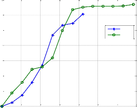
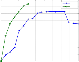
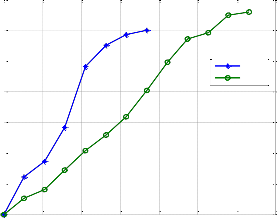
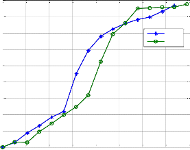
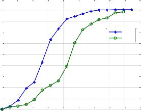
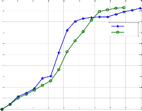
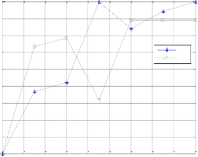
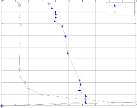
The sample cold extruded with mild steel die at entry angle (α) of 15o (CM 15), exhibited a higher extrusion pressure over that of CT15 within a strain of 0 and 0.38, which yielded at a lower pressure as shown in Figure 3(a). From study, sample CT15 had better elongation compared to the sample extruded with a mild steel die (CM15) and hence, the percentage elon- gation for CT15 is greater than that for CM15 as shown in Fig- ure 3(a) below. The maximum pressure needed to deform CT15 is higher since its maximum pressure is 660Mpa, which is higher than 600Mpa at CM15. Sample CM30 yielded readily at a pressure of 10MPa than CT30, which yielded at 90MPa (Figure 3(b)).The elongation of CT30 is superior to that of CM30. Hooke’s law is obeyed until an extrusion pressure of about 86MPa was attained at a small strainn of 0.05 for CM45 while CT45 obeyed this law up to a pressure of 375MPa with similar sample strain as shown in Figure 3(c). The mild steel die enables slips and dislocation movement of the sample to take place with ease than the tool steel dies, hence, having a better elongation. Samples CM60 and CT60 (Figure 3(d)) show similar response to extrusion pressure. Although, the differ- ence in their maximum pressure is small, the maximum pres- sure for CM60 is less than the maximum pressure to deform CT60.
Sample CM75 had a better response to elongation than sample CT75 as shown in Figure 3(e). The maximum pressure to de- form in CM75 is 912MPa and this is greater than that which deforms in CT75 (890MPa) while samples extruded in mild and tool steel dies of 90o entry angle (CM90 and CT90), have
700
600
500
400
300
200
100
0
900
800
700
600
500
400
300
200
CM30
CT30
0 0.1 0.2 0.3 0.4 0.5 0.6 0.7 sample strain
(b)
CM45
CT45
comparable responses at similar extrusion pressure up to
200MPa (Figure 3(f)). The maximum pressures are comparable
with CM90 at 923MPa while for CT90, at 930MPa respectively.
100
0
0 0.1 0.2 0.3
0.4 0.5 0.6 0.7 0.8 0.9 s le s
700
900
amp
(c)
train
600
800
500
400
CM15
CT15
700
600
500
CM60
CT60
300
400
200
300
100
0
0 0.1 0.2 0.3 0.4 0.5 0.6 0.7 sample strain
(a)
200
100
0
0 0.1 0.2 0.3 0.4 0.5 0.6 0.7 0.8
sample strain
(d)
IJSER © 2012
http://www.ijser.org
International Journal of Scientific & Engineering Research, Volume 3, Issue 3, March-2012 4
ISSN 2229-5518

1000
900
800
700
600
500
400
300
200
100
0
1000
900
800
700
600
CM75
CT75
0 0.1 0.2 0.3 0.4 0.5 0.6 0.7 0.8 0.9 sample strain
(e)
CM90
CT90
500
400
300
200
100
0
0 0.1 0.2 0.3 0.4 0.5 0.6 0.7 0.8 0.9 sample strain
(f)
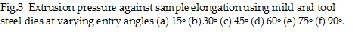
Sample CT30 (Figure 5(b)) shows a precipitation of Mg2Si phase at grain boundaries with precipitated AlFeSi, which has stronger intensity than the fourth phases in its structure com- pared to CM30, which has precipitates of Mg2Si in its structure clustering fairly along the grain boundaries as shown in Fig- ure 5(a).
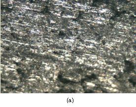
3.2 Effects on microstructure
Sample CT15 shows existing fine Mg2Si crystals at the grain boundaries which are along the slip direction compared to the structure of the sample extruded in mild steel die, CM15, which contains clusters of Mg2Si precipitates along the grain boundaries in a matrix containing fine crystals of α-aluminum, AlFeSi and other inter metallics as shown in Figures 4(a) and (b).
IJSER © 2012
http://www.ijser.org
International Journal of Scientific & Engineering Research, Volume 3, Issue 3, March-2012 5
ISSN 2229-5518

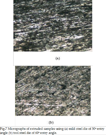
The deformation texture prevails in the matrix with increase in Mg2Si precipitates which are well distributed in the matrix (Figure 7(a)). The volume fraction of AlFeSi and the fourth phases remain the same. The slip directions re visible. Some Mg2Si precipitates are formed along slip directions as well as distorted grain boundaries. The structure of sample CT60 (Figure 7(b)) reveals a decrease in volume of Mg2Si precipi- tates with crystal shapes ranging from needle-like to spherical. This phase is fairly distributed in the matrix.. There is howev- er, increase in volume fraction of AlFeSi and fourth phases, which are inseparable but higher than that in CM 60. Slip lines are as pronounced as they were previously.
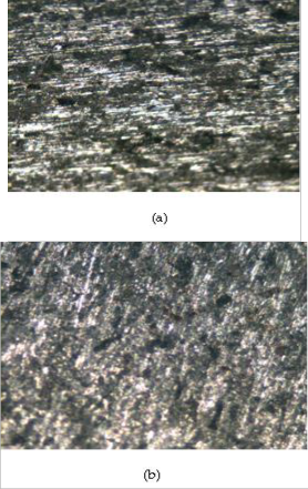
Figure 6(a) shows that there is an increase in Mg2Si precipi- tates in clustered form in the matrix with some of them been formed along the slip lines. Alpha- aluminum and AlFeSi crys- tals are displayed in the slip direction. In Figure 6 (b), there is an increase in the proportion of Mg2Si at grain boundaries with increase in AlFeSi and fourth phases which are roughly equal. The slip lines are not as pronounced as the sample ex- truded in CM 45.
The Mg2Si crystals in Figure 8(a) are at the grain boundaries in clustered form and stretched along the slip directions. The crystals of α –aluminum ,AlFeSi and the fourth phases havie similar volume fractions. Figure 8(b) shows that there is reduc- tion in the clustering of Mg2Si when compared to CM75 with its precipitates been much finer and well distributed in vary- ing shapes ranging from needle-like to spherical. The finess of aluminum, AlFeSsi and fourth phases are maintained.
IJSER © 2012
http://www.ijser.org
International Journal of Scientific & Engineering Research, Volume 3, Issue 3, March-2012 6
ISSN 2229-5518
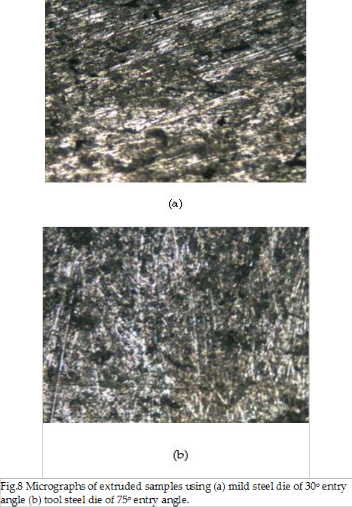
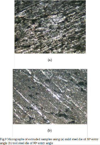
Figure 9 (a) reveals that the Mg2Si precipitates are at the grain boundary in clustered form with increase in its volume frac- tion in comparison to the previous ones. Crystals of α- aluminum AlFeSi and the fourth phases are fine in the matrix. The volume fraction of AlFeSi and the fourth phases remained the same. The crystals in the matrix of the structure for CT90, (Figure 9(b)) are very fine with considerable distortion in the Mg2Si precipitates in the matrix. There is significant increase in volume of AlFeSi and fourth phases. There is considerable reduction in the volume of Mg2Si crystals precipitated.
3.3 Effects on hardness
The hardness of each extruded sample (Figure 10) increases as the entry angle increases. Samples extruded on tool steel dies had greater hardness values than those extruded on mild steel dies though, with a slight difference. The hardness values for the two die materials at 75oand 90o are almost the same.
IJSER © 2012
http://www.ijser.org
International Journal of Scientific & Engineering Research, Volume 3, Issue 3, March-2012 7
ISSN 2229-5518

100
90
80
70
60
50
40
30
20
10
0
Mild
Tool
0 10 20 30 40 50 60 70 80 90

Die entry angle
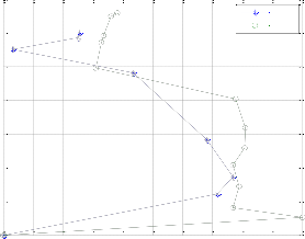
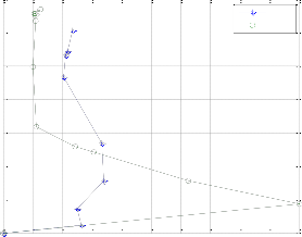
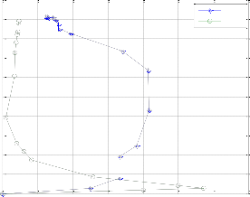
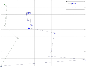
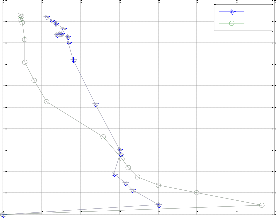
compared to that extruded in mild steel of the same entry angle (CM15). This means the ram traveled with ease when CT15 is used compared to CM15. The ram velocity for CT30 reduces gradually with an increasing extrusion pressure till it becomes constant at 0.022mm/s between extrusion pressures of 300MPa and 700MPa (Figure 12(b)). There are fluctuations in ram velocity as extrusion pressure for CM30 increases. The Figure shows that the sample deforms with ease when ex- truded in a mild steel die of 30o entry angle than in tool steel die of the same entry angle. Samples in Figure 12(c) show a comparable response to deformation but at different extrusion pressures and ram velocities. The maximum ram velocity for CM45 is 0.011mm/s. This means for a better deformation re- sponse, CM45 is preferable. There is a gradual decrease in ram velocity for the sample extruded in mild steel die of 60o entry angle (CM60) as shown in Figure 12(d). This gradual reduc- tion in ram velocity is also similar for CT60 until a velocity of
0.027mm/s is reached at an extrusion pressure of 317MPa.The
3.4 Effect on percentage elongation
Figure 11 shows that the samples extruded using tool steel die have better percentage elongation than those extruded with mild steel dies at die entry angles of 15o,30o and 60o respective- ly. The percentage elongation using tool steel die remains 79% at entry angles of 60o, 75o and 90o. The Figure also shows that the best percentage elongation is obtained at entry angles of
45o and 90o on mild steel die.
90
80
70
60 Mild
Tool
50
ram velocity remains nearly constant until the maximum ex- trusion pressure is attained (847MPa). The ram travelled with ease on CM60o compared to CT60. Figure 12(e) shows the gradual increase in ram velocity for CM75 up to 0.208 mm/s when a pressure of 450MPa was reached. The ram velocity decreases gradually from this value (0.208mm/s) to
0.064mm/s, when the maximum extrusion pressure, 912MPa
is reached. The pattern of extrusion pressure - ram velocity
relationship for CT75 in Figure 12(e) is similar to that of CT60 in 12(d) (extrusion pressures and ram velocities are not simi- lar) The ease of deforming sample with mild steel of 75o entry angle is better than that for tool steel of similar entry angle. Ram velocity for samples extruded in mild and tool steel dies of 90o entry angle (CM90 and CT90), as revealed in Figure
12(e) decrease gradually at increasing extrusion pressure. The
ram velocity for CM90 is greater than that for CT90, therefore,
the ram travels with ease on mild steel die
700
40
30 600
CM15
CT15
20
10
0
0 10 20 30 40 50 60 70 80 90
Die entry angle
500
400
300

200
3.5 Effects on ram velocity
Ram velocity reduces gradually as the extrusion pressure in- creases except in some instances where the reverse happens as extrusion pressure increases. This could be as a result of de- formation not taking place at the same rate in the sample. Fig- ure 12(a) shows that the ram velocity for sample extruded in tool steel of die entry angle of 15o (CT15) declined slowly
100
0
0 0.02 0.04 0.06 0.08 0.1 0.12 0.14 0.16 0.18 0.2
Ram velocity(mm/s)
(a)
IJSER © 2012
http://www.ijser.org
International Journal of Scientific & Engineering Research, Volume 3, Issue 3, March-2012 8
ISSN 2229-5518
700
600
500
CM30
CT30
1000
900
800
700
CM75
CT75
400
300
600
500
400
200
300
100
200
100
0
0 0.02 0.04 0.06 0.08 0.1 0.12 0.14 0.16 0.18 0.2
Ram velocity(mm/s)
(b)
0
0 0.05 0.1 0.15 0.2 0.25 0.3 0.35
Ram velocity(mm/s)
(e)
900
800
700
CM45
CT45
1000
900
800
CM90
CT90
600
500
400
300
200
700
600
500
400
300
200
100
100
0
0 0.05 0.1 0.15 0.2 0.25
Ram velocity(mm/s)
(c)
0
0 0.05 0.1 0.15 0.2 0.25 0.3 0.35
Ram velocity(mm/s)
(f)
900
800
700
600
500
400
300
200
CM60
CT60
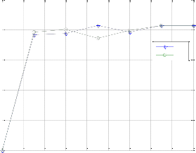
3.6 Effects on extrusion ratio
Figure 13 shows that the extrusion ratio has the lowest value of approximately 1.9 when the sample was extruded in a mild steel die of 45o die entry angle. The maximum value of 2.07 is recorded when the sample was extruded in mild steel of die at
45o, 75o and 90o entry angles respectively. The same result is
recorded with tool steel die of 75o and 90o die angles.
100
0
0 0.02 0.04 0.06 0.08 0.1 0.12 0.14 0.16 0.18 0.2
Ram velocity(mm/s)
(d)
IJSER © 2012
http://www.ijser.org
International Journal of Scientific & Engineering Research, Volume 3, Issue 3, March-2012 9
ISSN 2229-5518
2.5
2
[4] S.O.Onuh, M. Ekoja and M.B," Adeyemi, "Effects of Die Geometry and Extrusion Speed on the Cold Extrusion of Alusminum and Lead Alloys", .Materials Processing Technology, vol.132,pp. 274 -285,2003.
1.5
1
0.5
0
Mild
Tool
0 10 20 30 40 50 60 70 80 90
Die entry angle
[5] S. Yuan, "Effects of Guiding Angle on Plastic Metal Flow and Defects in Extrusion of Aluminum Alloy. Journal of Mate- rials Science and Technology, no.2,vol24, pp.256 -260,2008.
[6] P. Tiernan, M.T. hillery, B. Draganeccu, M. Gheorghe, "Modeling of Cold Extrusion with Experimental Verification". Journal of Materials Processing Technology, vol.16, pp.360 – 366,
2005.
[7] S. Karabay, M. Zeren, M. Yilmaz, "Investigating Extrusion
Ratio Effect on Mechanical Behaviour of Extruded Alloy AA-
6101 From the Billets Homogenised-Rapid Quenched and As-
Cast Conditions", Journal of Materials Processing Technology,
no.2, vol.160, pp.138-147, 2005.
4 CONCLUSION
Successful cold extrusion of 6063 aluminum alloy with mild and tool steel entry die angle was achieved. At 90o, the ex- truded samples have superior hardness independent of the die material. The experimental results show that aluminum alloy deforms better when the die material is made of mild steel with die entry angles of 45o, 75o and 90o than on tool steel. The percentage elongation of extruded samples at these entry an- gles is also superior, reason been that the ram velocity under applied pressure, is a function of the ease at which deforma- tion takes place. Extrusion with a mild steel die at 45o entry angle (CM45) engenders ease in ram travel and this could be attributed to increase in Mg2Si precipitates clustering in the matrix. The difference in the maximum extrusion pressure and hardness between tool steel and mild steel dies is small and considering the economy of the work, mild steel can still be used to get desirable results since it is cheaper than tool steel.
REFERENCES
[1] A. F.M. Arif, A.K. Sheikh, S.Z. Qamar,K.M. Al-Fuhaid," Variation of Pressure with Ram Speed and Die Profile in Hot Extrusion Alloy 6063", Materials and Manufacturing processes, vol.16, pp. 701 – 716, 2001.
[2] A. F.M. Arif, A.K. Sheikh, S.Z. Qamar, K.M. Al-Fuhaid," Product Defects in Aluminum Extrusion and their Impacts on Operational Cost", Materials and Manufacturing processes, vol.5, pp. 137 – 154,2005.
[3] I. Flitta, T. Sheppard," Nature of Friction in Eextrusion Process and its Effects on Material Flow", Materials Science and Technology, vol. 19,pp.837 – 843,2003.
[8] P.K. Saha, Aluminium Ekstrüzyon Technology, ASM In- ternational, The Material International Society, 2000.
[9] A. Loukus, G. Subhash, M. Imaninejad, "Mechanical Prop- erties and Microstructural Characterization of Extrusion Welds in AA6082-T4, Journal of Materials Science, no.17 vol. 39, pp. 6561-6569, 2004.
[10] ASM Metals Handbook," Metallographic Technique for
Aluminum Alloys", Vol.7, pp.120-124.
Gbenebor, O.P is currently an accademic at the College of
Science and Technology, Covenant University, P.M.B
1023, Ota, Ogun state, Nigeria. E-mail: gbeneborphi- lips@yahoo.co.uk
Adeosun, S.O (Ph.D) is currently an accademic at the Fa- culty of Engineering, University of Lagos, Yaba, Lagos, Nigeria.
Fayomi, O.S is currently a researcher at the Faculty of En- gineering and Built Environment,Tshwane University of Technology, P.M.B X680, Pretoria, South Africa
Joseph, O.O is currently an academic at the College of
Science and Technology, Covenant University, P.M.B
1023, Ota, Ogun state, Nigeria.
IJSER © 2012
http://www.ijser.org