International Journal of Scientific & Engineering Research, Volume 4, Issue 12, December-2013 1780
ISSN 2229-5518
The Global Navigation Satellite System (GNSS) and Indian Satellite Based Augmentation System (GAGAN)
Jitu Sanwale, Dhan Jeet Singh, U G Salawade
Abstract— The Global Positioning System (GPS) has been used extensively for providing navigation, positioning and time information across the world for air vehicles, ships, missiles and Geographic Information System (GIS). The Global Navigation Satellite System (GNSS) of Russia (GLONASS) is also getting momentum in terms of civilian and military applications. In the series of satellite constellation GALILEO is getting ready for full fledge deployment. The GNSS alone is not sufficient for high precision position applications such as approach and landing of air vehicles. Hence, to achieve the appropriate level of accuracy these constellations need to be augmented. This paper describes the various methods of augmentation along with detailed description of Indian Satellite based augmentation system. The GAGAN system is an Indian Satellite Based Navigation Augmentation System. The GAGAN will provide a civil aeronautical navigation signal consistent with International Civil Aviation Organization (ICAO) Standards and Recommended Practices (SARPS) as established by the GNSS Panel.
Index Terms—GAGAN, GALILEO, GLONASS, GPS, GBAS, ABAS, SBAS
—————————— ——————————
1 INTRODUCTION
N the modern world, satellite-based radio systems are be- ing used in aviation as well as non-aviation sectors for
tion 4 describes an Indian SBAS (GAGAN) in great detail. Fi- nally, conclusion is presented in section 5.
communication, navigationI, surveJillance, air tSraffic manage- ER
ment and various other purposes. The past decade has seen a
rapid development of several GNSSs. Some of them are al- ready in service such as GPS & GLONASS [1]-[3]. However, some GNSSs are still under development e.g. GALILEO by European Union [2] and Compass by China. The position ac- curacy achievable with these core constellations are not good enough for various service requirements such as accurate posi- tioning and precision approach and landing of aircrafts. Hence to achieve the appropriate level of accuracy these constella- tions need to be augmented. Three types of augmentation techniques are used to enhance the position accuracy: Ground Based Augmentation System (GBAS), Aircraft Based Augmen- tation System (ABAS), and Space Based Augmentation System (SBAS).
GPS Aided Geo-Augmented Navigation (GAGAN) system is a
planned implementation of a regional satellite based augmen- tation system by the Indian government. This system will help in up gradation of communication, navigation and surveil- lance systems. This will also help in landing of aircrafts in ad- verse weather conditions and uneven terrain. Once completely implemented, GAGAN will be the fourth operational Satellite Based Augmentation Systems after American Wide Area Augmentation System (WAAS), the European Geostationary Navigation Overlay Service (EGNOS) and the Japanese MTSAT Satellite-based Augmentation System (MSAS). Since the GAGAN is an aiding system to GPS, therefore, in this pa- per GPS is considered a representative of GNSS family.
This paper describes the GPS and illustrates the limitations posed by GNSS for precise positioning applications in section
2. Section 3 deals with various augmentation techniques. Sec-
2 GLOBAL NAVIGATION SATELLITE SYSTEM (GNSS)
2.1 Global Positioning System (GPS)
GPS is developed and maintained by the Department of De- fense (DoD), USA and is officially named Navigation Signal Timing and Ranging (NAVSTAR) Global Positioning System. The GPS system uses receivers to calculate position by meas- uring the distance between the receiver and three or more GPS satellites. The distance to each satellite is measured by the time delay between transmission and reception of each GPS radio signal. The calculated distance is called pseudo range. The GPS signals also carry information about the satellite’s loca- tion. By determining the satellite’s position and pseudo ranges to the receiver, the receiver can compute its location using tri- lateration. Because receivers do not have perfectly accurate clocks, an extra satellite is tracked to account for clock error. The GPS has architecture of three segments: 1) Space segment,
2) Control Segment, and 3) User segment [1]-[3]. The space segment includes 24 satellites at 20,000Km altitude, with six orbital levels as shown in figure 1 and a 12 hour period. The second segment includes the earth stations to control the satel- lite trajectories. The third segment includes GPS receivers us- ing two frequencies in L1 and L2 band.
GPS satellites broadcast navigation data, modulated on the L1
(1575.42 MHz) and L2 (1227.60 MHz) band carrier frequencies. The data contains coarse ephemeris data for all satellites in the constellation, precise ephemeris data for this particular satel- lite, timing data and model correction parameters needed by a GPS receiver to make a correct ranging measurement. This data is included in the 37,500 bit navigation message, which
IJSER © 2013 http://www.ijser.org
International Journal of Scientific & Engineering Research, Volume 4, Issue 12, December-2013 1781
ISSN 2229-5518
takes 12.5 minutes and is send at 50 bps rate.
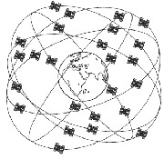
Fig.1 GPS Satellite Constellation
The satellites broadcast two forms of ranging codes: the Coarse/Acquisition (C/A) code, which is freely available to the public and the restricted Precise code (P-code), which is usually reserved for military applications specifically for US defense and allied forces only. Each satellite has a different C/A code. The C/A code is a 1,023 bit long pseudo-random code, broadcasts at 1.023 MHz and repeating every millisec- ond. Each satellite sends a distinct C/A code which allows it to be uniquely identified. Similarly the P-codes are broadcast
at 10.23 MHz, but it repeats only once a week.
3 GNSS AUGMENTATION
All the limitations mentioned in section 2.2 requires an imme- diate attention to address all the issues. Higher accuracy is available today by using GPS in combination with augmenta- tion systems. These enable real-time positioning to within a few centimeters, and post-mission measurements at the milli- meter level. The U.S. government is committed to moderniz- ing the GPS constellation to enable higher civilian accuracy without augmentations.
The ongoing GPS modernization program is adding new civil- ian signals and frequencies to the GPS satellites, enabling ion- ospheric correction for all users. In turn, the accuracy differ- ence between military and civilian GPS will disappear. But GPS with P-code will continue to provide important ad- vantages in terms of security and jam resistance.
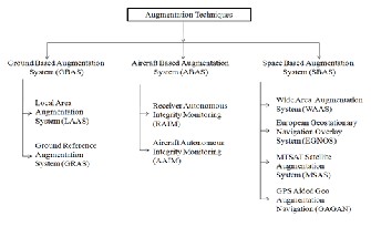
Augmentation of GNSS is a method of improving the naviga- tion system's attributes, such as accuracy, reliability, and availability, through the integration of external information into the calculation process. There are many such systems in place and they are generally named or described based on how the GNSS receiver uses the external information. The augmentation techniques are classified as:
The U.S. government is committed to providing GPS to the civilian community at the performance levels specified in the GPS Standard Positioning Service (SPS) Performance Standard [4]. The accuracy users attain depends on various factors that include propagation delay, multipath, low accuracy receiver clock and the receiver noise. Some of the error sources and its effects are tabulated in table-1 [5].
Table- 1 Sources of Error
2.2 GNSS Limitations
In addition to accuracy consideration, there are other factors also which limit usage of GNSS such as [6], [9]:
• GPS standalone cannot satisfy the integrity, accuracy and availability requirements for all phase of flight.
• Integrity is not guaranteed, since all satellites may not be satisfactorily working all times.
• Time to alarm could be from minutes to hours and there is no indication of quality of service.
• Accuracy is not sufficient even with selective availability
(S/A) off for cat-I landing.
• For GPS & GLONASS standalone systems availability &
continuity are not assured.
3.1 Ground Based Augmentation System (GBAS)
The GBAS supports local augmentation (at airport level) of the primary GNSS constellation(s) by providing enhanced levels of service that support all phases of approach, landing, depar- ture and surface operations. The GBAS is intended primarily to support precision approach operations. The GBAS describes a system that supports augmentation through the use of ter- restrial radio messages. The GBAS composed of one or more accurately surveyed ground stations, which take measure- ments concerning the GNSS, and one or more radio transmit- ters, which transmit the information directly to the end user. Generally, GBAS networks are considered localized, support- ing receivers within 20 km, and transmitting in the very high frequency (VHF) or ultra high frequency (UHF) bands. The United States Local Area Augmentation System (LAAS) and Nationwide Differential GPS System (NDGPS) are examples of Ground Based Augmentation Systems.
IJSER © 2013 http://www.ijser.org
International Journal of Scientific & Engineering Research, Volume 4, Issue 12, December-2013 1782
ISSN 2229-5518
3.2 Aircraft Based Augmentation System (ABAS)
The ABAS augments the information obtained from GNSS with information available on-board the aircraft by using sep- arate principles realized for GNSS. Due to this reason, it is not necessarily subjected to the same sources of error or interfer- ence. Receiver Autonomous Integrity Monitoring (RAIM) and Aircraft Autonomous Integrity Monitoring (AAIM) are the techniques used in ABAS.
RAIM is a technique used to provide a measure of the trust which can be placed in the correctness of the information sup- plied by GNSS. It uses redundant measures of GNSS pseudo- ranges, when more satellites are available than needed to pro- duce a position fix.
AAIM uses the redundancy of position estimates from multi- ple sensors, including GNSS, to provide integrity perfor- mance. Inertial Navigation Systems (INS) on board is used as an integrity check on GNSS data when RAIM is unavailable. INS uses different motion sensors (accelerometers) and rota- tion sensors (gyroscopes) to continuously calculate via dead reckoning the position, orientation, and velocity of the aircraft without the need for external references.
3.3 Space Based Augmentation System (SBAS)
The SBAS supports wide-area or regional augmentation even
plementation over Indian region with minimum set of ele- ments, and to study the ionosphere over the Indian region & to collect data for system development and necessary modifi- cations for the Indian region for the Final Operational Phase. The infrastructural configuration required for TDS phase is shown in figure 2.
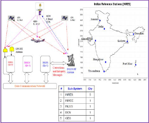
Fig.2 GAGAN TDS configuration [10]
continental scale through Ithe useJof GEO saStellites which ER
broadcast the augmentation information. A SBAS augments primary GNSS constellation(s) by providing GEO ranging, integrity and correction information [6]. While the main goal of SBAS is to provide integrity assurance, it also increases the accuracy with position errors below 1 meter. Such systems are commonly composed of multiple ground stations, located at accurately surveyed points. The ground stations take meas- urements of one or more of the GNSS satellites, the satellite signals, or other environmental factors which may impact the signal received by the users. Using these measurements, in- formation messages are created and sent to one or more satel- lites for broadcast to the end users. There are already three operational (WAAS, MSAS, EGNOS), three under implemen- tation (GAGAN, SDCM, SNAS) while others are under feasi- bility studies, for instance SACCSA systems in the world.
4 THE GPS AIDED GEO AUGMENTED NAVIGATION
(GAGAN)
The GAGAN system is jointly developed by Indian Space Re- search Organization (ISRO) and Airports Authority of India (AAI), to deploy and certify an operational SBAS over Indian Flight Information Region. When commissioned for service, GAGAN will provide a civil aeronautical navigation signal consistent with International Civil Aviation Organization (ICAO) Standards and Recommended Practices (SARPS) as established by the GNSS Panel. GAGAN implementation is carried out in two phases [7]-[10]:
• Technology Demonstration System (TDS): The objec- tive of TDS phase was to demonstrate feasibility of SBAS im-
• Final Operational Phase (FOP): The FOP intended for
providing a certified satellite based navigation system for all phases of flight by augmenting the TDS system suitably. Fur- ther to provide redundancies, Implement Suitable region spe- cific IONO model, Get safety Certification for the system for the Civil Aviation use from DGCA, the regulatory authority in India. The GAGAN satellite configuration and required ground infrastructure for FOP is shown in figure 3.
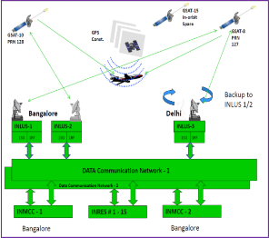
Fig.3 GAGAN FOP configuration [10]
The final GAGAN network involves the establishments of 15
Indian Reference Stations (INRES), 3 Indian Land Up-link Sta- tions (INLUS), 2 Indian Master Control Centers (INMCC), 2
Geo-Stationary Navigation Payloads (GSAT-8 & GSAT-10) in
IJSER © 2013 http://www.ijser.org
International Journal of Scientific & Engineering Research, Volume 4, Issue 12, December-2013 1783
ISSN 2229-5518
C & L bands and with all the associated software and commu- nication links [10]. All INRESs are integrated with redundant communication links (which include 2 OFC & 2 VSAT links) to transfer data to INMCC.
GPS satellites data is received and processed at widely dis- persed Indian Reference Stations (INRESs), which are strategi- cally located to provide coverage over the required service volume. Data is forwarded to the Indian Master Control Cen- ter (INMCC), which processes the data from multiple INRESs to determine the differential corrections and residual errors for each monitored GPS satellite and for each predetermined Ion- ospheric Grid Point (IGP). Information from the INMCC is sent to the INLUS and uplinked along with the GEO naviga- tion message to the GAGAN GEO satellite. The GAGAN GEO satellite downlinks this data to the users via two L-band rang- ing signal frequencies (1 MHz, BPSK signal at 1575.42 MHz of L1 band and 10 MHz, BPSK signal at 1176.45 MHz of L5).
The Final System Acceptance Test (FSAT) was completed dur- ing July 2012 and the GAGAN signal in space was evaluated using SBAS receivers at various locations across the country and the system performance was verified [10]. SBAS user re- ceivers were deployed at various locations within India, and the performance in terms of accuracy and integrity were moni-
tored and were found to be within specifications.
integrity necessary to enable users to rely on GPS for all phas- es of flight. This will enable Cat-I landing at Indian regional airports under the GAGAN service range.
REFERENCES
[1] J. Bao-Yen Tsui, “Fundamentals of Global Positioning Sys- tem Receivers: A Software Approach”, 2nd Edition, A John Wiley & Sons, Inc, Publication,2005.
[2] J. Mendizabal, R. Berenguer and J. Melendez, “GPS and GALILEO: Dual RF Front-end receiver design, fabrication and test”, McGraw Hill, 2005.
[3] J. G. McNeff, “The Global Positioning System”, IEEE
transactions on microwave theory and techniques, Vol. 50, No.
3, March 2002.
[4] “Global Positioning System Standard Positioning Service
Performance Standard”, 4th Edition, Sep 2008.
[5] N. Acosta and J. Toloza, “Techniques to improve the GPS precision”, International Journal of Advanced Computer Sci- ence and Applications, Vol. 3, No. 8, 2012.
[6] L.Wanninger, “The Future is Now: GPS+GLONASS+SBAS=GNSS”, GPS World, July 2008,
available online at at www.gpsworld.com.
[7] S.V. Kibe, “Indian plan for satellite-based navigation sys-
tems for civil aviation”, Current Science, Vol. 84, No. 11, 10
June 2003.
IJSER
GSAT-8 is providing GAGAN signal at PRN-127, while GSAT-
10 is providing GAGAN signal at PRN128. GSAT-15 will serve as an in-orbit spare once it is launched in the near future [10]. Further, GAGAN is the first system in the world that is being developed to serve the equatorial anomaly region with its unique IONO algorithm designed and developed by scientists and experts from ISRO & AAI in collaboration with Raytheon. The GAGAN is designed to provide the additional accuracy, availability, and integrity necessary to enable users to rely on GPS for all phases of flight, from en route through approach for all qualified airports within the GAGAN service volume. GAGAN will also provide the capability for increased accura- cy in position reporting, allowing for more uniform and high- quality Air Traffic Management (ATM).
In addition, GAGAN will provide benefits beyond aviation to all modes of transportation, including maritime, highways, railroads and public services such as defense services, security agencies, telecom industry and personal users of position loca- tion applications.
5 CONCLUSION
The Satellite constellation based Global Navigation Satellite Systems (GPS, GLONASS & GALILEO) are meant for provid- ing navigation, positioning and time information across the world for various applications. However, for precision posi- tions and safety critical applications the GNSS alone cannot meet the requirements in terms of accuracy, integrity and availability. Hence, various augmentation methods are adopt- ed to improve the accuracy of GNSSs. The GAGAN is a SBAS designed to provide the additional accuracy, availability, and
[8] S. Rao, A. S. Ganeshan, P. Soma and S. Pal, “GAGAN
(GPS Aided Geo Augmented Navigation)- Indian SBAS
System”, 58th International Astronautical Congress, 2007.
[9] K. N. S. Rao, “GAGAN- The Indian satellite based aug-
mentation system”, Indian Journal of Radio & Space Physics,
Vol. 36, August 2007, pp. 293-302.
[10] C. R Sudhir, ”Indian SBAS System - GAGAN” ,GAGAN-
FOP/PMR-05, GNSS-Asia India-Industry Workshop, 19th
Feb 2013.
Authors:
IJSER © 2013 http://www.ijser.org
International Journal of Scientific & Engineering Research, Volume 4, Issue 12, December-2013 1784
ISSN 2229-5518

Jitu Sanwale received the B.E. degree in Electronics & Instru- mentation Engineering from SGSITS, Indore in 2006. He also received the M.Tech degree in Communication Systems from IIT Roorkee in 2008. He is an associate member of Aeronauti- cal Society of India (AeSI) and Institution of Electronics and Telecommunication Engineers (IETE).
He joined the Aircraft Research & Design Centre, Hindustan
Aeronautics Limited in 2008 as a design engineer. Presently, he is working as Deputy Manager (Design) in AURDC, HAL Nasik. His areas of interest include Inertial and Global Posi- tioning System, Radio Navigation, Flight Control System and Adaptive Signal Processing.
AURDC, HAL, Nasik in Oct 1986. Presently, he is HOD of De- sign Electrical Department and holding a post of Dy General Manager (Design).
He has specialization in electrical & armament systems of fighter aircraft. He has made significant contribution in air- craft upgrade and responsible for several modifica- tions/improvements on fighter aircraft of Russian origin for flight safety, reliability, maintainability, enhancement in oper- ational capability, new/advanced weapon integration etc.
He has presented many technical papers at National & Inter- national seminars. He is a recipient of “R & D award” from Chairman, HAL for his significant contributions in design & development.
He is a life member of Aeronautical Society of India and pres-
ently holding the post of Honorary Treasurer for The Aero- nautical Society Of India, Nasik Branch.

Dhan Jeet Singh received the B.Tech degree in Electronics & Communication Engineering from BIET, Jhansi in 2005. He is a life time member of Aeronautical Society of India.
He joined the AURDC of Hindustan Aeronautics Limited in
2005 as a design engineer. Presently, he is working as Manager (Design) in Flight Controls & Navigation group of Design Electrical department. His areas of interest include radio navi- gation, flight control system, Model Predictive Control and system identification.

U G Salawade graduated in Electrical Engineering from Shiva- ji University Kolhapur in 1985. He started his career in
IJSER © 2013 http://www.ijser.org